

Page 1
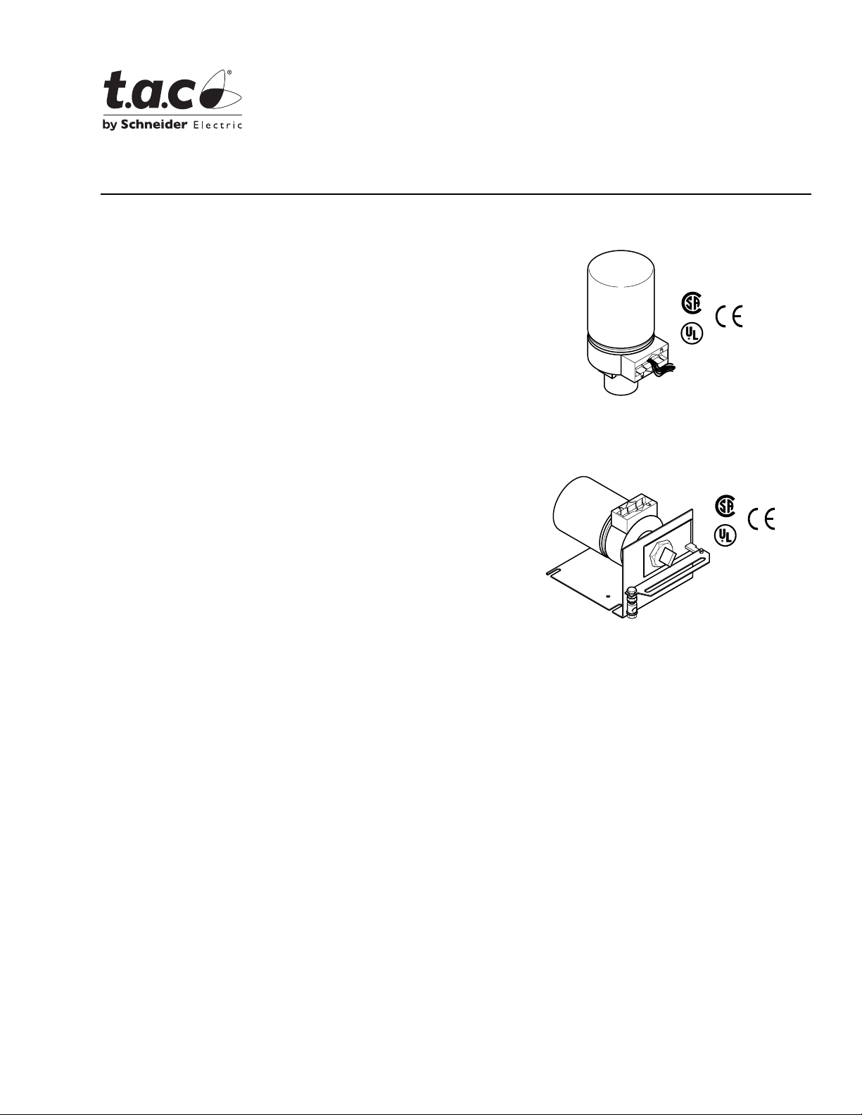
Application
The MPR-5600 series and MPR-5700 series actuators are
used for electronic proportional control of dampers and
valves which require a return to the normal position upon
power interruption. MPR-5600 series actuators are
compatible with controllers generating 4 to 20 mA input
signals, and MPR-5700 series actuators are compatible
with 135 Ω slidewire controllers (Series 90).
Features
• Spring return
MPR-5600 Series
MPR-5700 Series
Proportional Valve and Damper Actuators
General Instructions
MPR-561X Series
Valve Actuator
• 24 Vac, 120 Vac, and 240 Vac models are available
• Available in damper models or base models that require
damper or valve linkage
• Die cast lower housing with 1/2" conduit opening and
painted steel upper housing
• Hydraulic actuator with oil-immersed motor, transducer,
and pump
MPR-5600 Series
• Proportional actuators controlled by a variable mAdc
input signal
• Fixed 4 to 20 Adc operating range
• 82.5 Ω input impedance
• Adjustable actuator startpoint
MPR-5700 Series
• Proportional actuators controlled by a controller with a
135 Ω slidewire output
Applicable Literature
• TAC Environmental Controls Cross-Reference Guide,
F-23638
• TAC Environmental Controls Reference Manual,
F-21683
• TAC Environmental Controls Application Manual,
F-21335
• TAC Pneumatic Products Catalog, F-27383
MPR-5X3X Series
Damper Actuator
• AV-600 Hydraulic Actuator Valve Linkage Kit,
F-26279
• AV-601 Linkage Extension Set for AV-600 Valve
Linkage Kit, F-26280
• VB-7000 Valve Selection Guide, F-26094
• VB-7000 Cross Reference Guide, F-26175
• Material Safety Data Sheet MSDS-3 (Until Feb.
1989)
• Material Safety Data Sheet MSDS-12 (Currently)
Printed in U.S.A. 8-08 © Copyright 2008 TAC All Rights Reserved. F-23576-6
Page 2

SPECIFICATIONS
Actuator In puts
Control Circuit:
MPR-561X and -563X Series, Two-wire.
MPR-571X and -573X Series, Three-wire.
Input Impedance: 82.5 Ω for 4 to 20 mA input.
Power Input: Refer to Table-1 and Table-2.
Connections: Color- coded 4' (1.2 m) leads.
Actuator Outputs
Electrical:
Position Signals, Inter nal f eedback c ircui try pro vides posit ive pos iti oni ng of t he dam per
in relation to th e controller signal.
Startpoint Adjustment , Adjus tabl e potentiometer prov ides manual adjustment of the
actuator sta rtpoint.
Mechanical:
Stroke,
Damper Approximately 2" (51mm) from fully retracted to fully extended (includes
AM-601 linkage) .
Valve Approximately 9/16" (14.3 mm) from fully retracted to fully extended.
Nominal Damper Area, Actuator sizing should be done in accordance with damper
manufacturer’s specifications.
Output Torque Rating, The proportional output torque rating of 15 lb-in. (1.7 N-m) is
available throughout the entire stroke and is based on the lowest force available under
normal operati on, the spring return str oke, or at minimum (-10%) suppl y voltage.
Environment
Ambient Temperature Limi ts:
Shipping & Storage, -40 to 140° F (-40 to 60° C).
Operating,
Damper -20 to 140° F (-29 to 60° C).
Valve Refer to Table-3.
Humidity: 5 to 95% RH, non-condensing.
Location: NEMA Type 1, indo or onl y.
Agency Listings:
UL 873: Underwriters Laboratories (Fi le # E9429 Category Temperature-Indicati ng and
Regulating Equipment).
CSA: Certified for use in Canada by Underwriters Laboratories. Canadian Standard
C22.2 No. 24-93.
European Community: EMC Directive (89/336/EEC). Low Voltage Directive
(72/23/EEC).
2 © Copyright 2008 TAC All Rights Reserved. F-23576-6
Page 3

Table-1 Model Chart for Valve (Basic) Actuators.
Part Number
a
Actuator Power Input
AC
Voltage
+10/
Hz VA Watts
-15%
Timing in Seconds
@ 72° F (22° C)
No Load Stroke Retract
on
Extend Retract
Power
Loss
Required Linkages
Valve
Applications
Damper
Applications
MPR-5610 120
MPR-5611 240
MPR-5613 24
MPR-5710
MPR-5711
d
d
120 Compatible
240
50/60 18 10 60 30 15
AV-600
AV-601
c
AM-601
MPR-5713 24
a
These MPR-5X1X series valve actuators are compatible with VB-7XXX 1/2" to 2" valve bodies.
b
The MPR-5X1X series actuators are basic models which may be equipped for damper applications with the installation of an AM-601 linkage.
c
May be required for steam and hot water. Refer to Table-3.
d
These actuators are obsolete. They are listed here for reference only.
Table-2 Model Chart for Damper Actuators.
Actuator Power Input Timing in Seconds @ 72° F (22° C)
Part Number
a
AC
Voltage
+10/
-15%
Hz VA Watts
No Load Stroke
Extend Retract
Retract on
Power
Loss
Input
Signal
b
Compatible
with
4 to 20 m A
with
135 ¾
Slidewire
(Series 90)
Input
Signal
MPR-5630 120
Compatible
with
MPR-5633 24
MPR-5730
MPR-5733
b
b
120 Compatible
24
50 60 18 10 60 30 15
4 to 20 mA
135 ¾
Slidewire
(Series 90)
a
Damper models (MPR-5X3X) are provided with factory-installed damper linkages. Only base models (MPR-5X1X) require separately-ordered linkages.
b
These actuators are obsolete. They are listed here for reference only.
Table-3 Restriction s on Maxim um Ambie nt Temperature for Valve Actuators.
Maximum Temperature of Media
in the Valve Body
(Check Rating of the Valve)
°F (°C)
366 (186)
340 (171) 93 (34)
281 (138) 103 (39)
181 (83) 120 (48)
80 (26) 140 (60)
a
Maximum ambient temperature of the actuator must never exceed 140° F (60° C).
b
Minimum allowable ambient temperature of the actuators is -20° F (-29° C).
Maximum Ambient Temperature
of MPR-563X and -573X Series
AV-600 (Only)
°F (°C)
Do Not Use
a
AV-600 and AV-601
°F (°C)
88 (31)
140 (60)
with
b
a
a
a
F-23576-6 © Copyright 2008 TAC All Rights Reserved. 3
Page 4
ACCESSORIES
Common
11-1612 1/2" conduit bushing
Damper Linkages
AM-111 Crank arm for 5/16" diameter damper shaft
AM-112 Crank a rm for 3/8" diameter damper shaft
AM-113 Crank a rm for 1/2" diameter damper shaft
AM-115 Crank arm for 7/16" diameter damper shaft
AM-122 Linkage connector straight type
AM-123 Damper clip
AM-125 5/16" di am et er x 20 " da mp er rod
AM-125-048 5/16" di am et er x 48 " da mp er rod
AM-132 Ball joint con ne ct or
AM-161-3 Damper linkage kit
AM-601 Device includes mounting bracket, damper linkage with spring, and AM-122
straight conn ector. Required to modify (MPR-5X 1X series) valve actuato rs into 2"
AM-602 Spacer
Valve Linkages and Valves
AV-600 Valve linkage 1/2" to 1-1/4" (obsolete VB-9XXX)
AV-60 1 Valve linkage extension for hot water and steam applications; use wi th AV-600 &
AV-7600 Valve s linkage 1/2" to 2" to be used with VB-7XXX
VB-7XXX 1/2" to 2" valve bodies
VB-9XXX 1/2" to 1-1/4" valve bodies (obs olete)
TOOLS
TOOL-19 Spring compression tool for AV-600
TOOL-37 1-5/8" open-ended wrench
TOOL-209 135 Ω and 0 to 7 mA manual positioner
(factory-available)
(51 mm) stroke damper actuators.
AV-7600
TYPICAL APPLICATIONS (wiring diagrams)
Controller
135 Ω Slidewire
Temp.
Drop
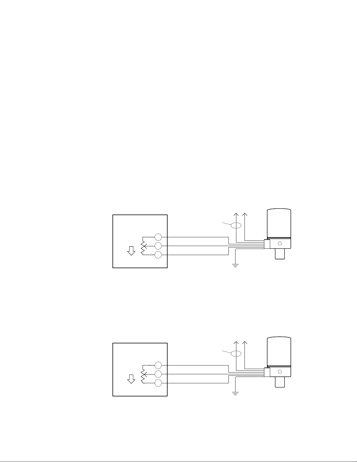
Sequence of operation: As the temperature decreases at the controller, R moves toward
B and the actuator shaft extends. On power loss to the actuator, the shaft retracts.
Notes:
1. The 135Ω controller is supplied by others.
2. The con troller has setpoint and throttling range (proportional band) adjustments.
Figure-1 Wiring Diagram - Decrease in Temperature Cause s Actuator Shaft to Extend.
Controller
135 Ω Slidewire
Temp.
Drop
W
R
B
W
R
B
24Vac Black/Blue
120Vac White
240Vac White/Black
Yellow/White
Red
Blue
24Vac Black/Blue
120Vac White
240Vac White/Black
Blue
Red
Yellow/White
To AC Power
Source
Black
Green
MPR-571X or MPR-573X
To AC Power
Source
Black
Green
MPR-571X or MPR-573X
Sequence of operation: As the temperature decreases at the controller, R moves toward
B and the actuator shaft retracts. On power loss to the actuator, the shaft retracts.
Notes:
1. The 135 Ω controller is sup plied by others.
2. The controller has setpoint and throttling range (proportional band) adjustments.
4 © Copyright 2008 TAC All Rights Reserved. F-23576-6
Page 5
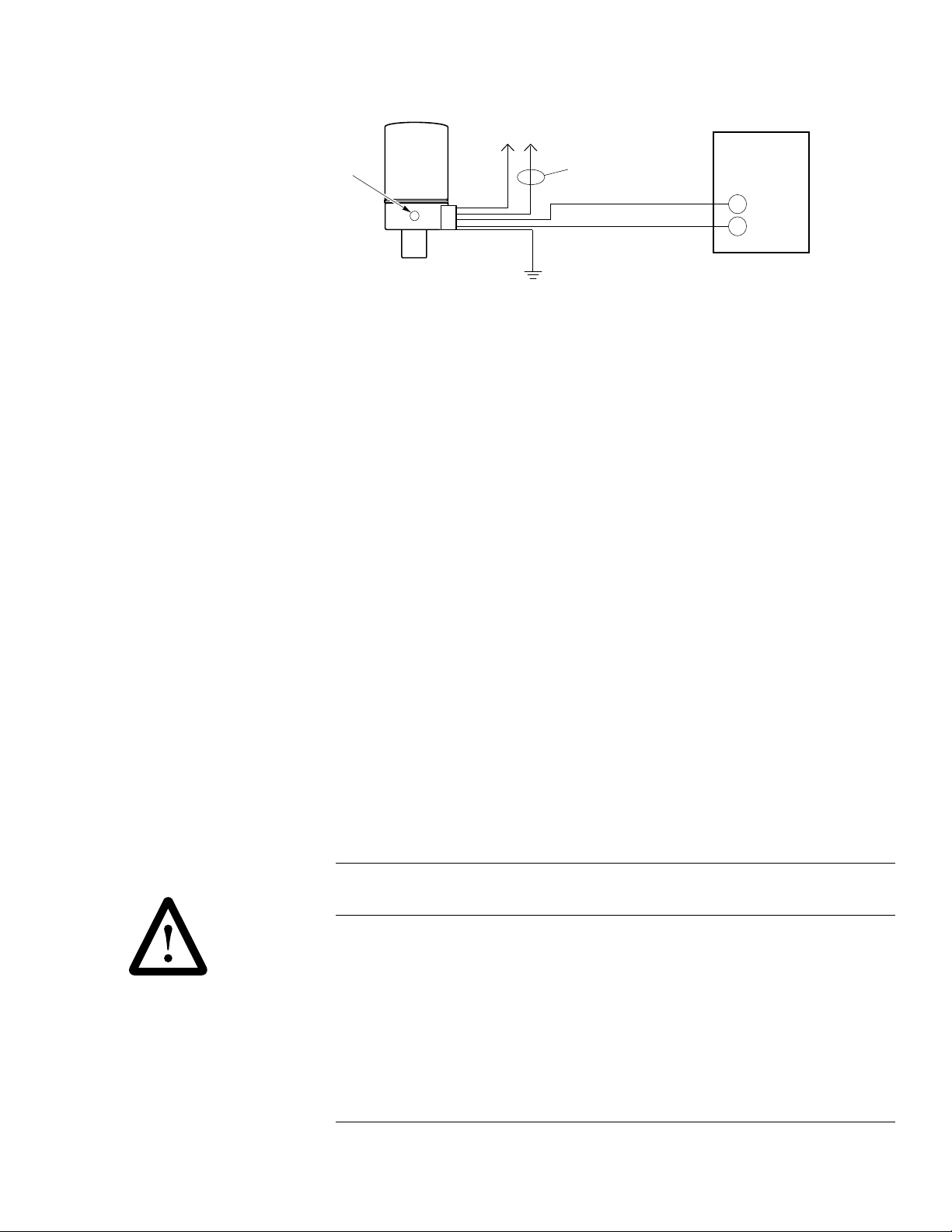
Figure-2 Wiring Diagram - Decrease in Temperature Cause s Actuator Shaft to Retract.
Actuator startpoint adjuster
is located behind the plug
button on the base
To AC Power
Source
Black
24Vac Black/Blue
120Vac White
240Vac White/Black
Yellow/White
Red
Controller
4 to 20 mAdc
Output Signal
+
-
Notes:
MPR-561X or MPR-563X
1. The 4 to 20 mAdc controller is supplied by others.
2. The controller has setpoint and throttling range (proportional band) adjustments. The controller may also
incorporate I (integral) and D (differential) functions.
3. To expose th e st art p oint ad ju ster , remo ve the pl ug bu tto n f rom t he bas e of t he actu at or by pr yi ng it of f wit h a
screwd riv er . Wi th a 4 mA cont rol le r in put sign al pr esen t , u se a s mall , si ng l e-sl ot ted scr e wdriv er t o adju st the
actuator startpoint potentiometer so that the actuator shaft just begins to extend.
4. The output can be either direct-acting or reverse-acting:
Direct-Acting (DA) Output: An increase in the measured media causes the controller output (4 to 20 mA
signal) to increase.
Reverse-Acting (RA) Output: An increase in the measured media causes the controller output (4 to 20 mA
signal) to decrease.
Sequence Of Operation:
An increase in the 4 to 20 mAdc sign al causes the MPR-561X or MPR-563X actuator shaft to extend. On
power loss to the actuator, the shaft retracts.
Figure-3 Wiring Diag ram - 4 to 20 mAdc Controllers.
Green
INSTALLATION
Inspection Inspect the pack age for damage. If damaged, notify the appropriate carrier immediately.
If undamaged, open the package and inspect the device for obvious damage. Return
damaged products.
Requirements • Job wiring diagrams
• Tools (not provided):
– D igital Volt-ohm Me ter (DVM)
– Appr opriate drill and drill bit for mou nti ng screws
– TOOL-19, Spring compression tool for AV-600
– TOOL-37, 1-5/8" open-ended wrenc h
– TOOL-209, 135
– Two 3/8 " wrenches
• Training: Installer must be a qualified, experienced technician
Ω and 0 to 7 mA manual positioner
Warning:
equipment damage .
Disconnect power supply before installation to prevent electrical shock and
Caution:
• Use electrostati c discharge precauti ons (e.g., use of wrist straps) during installatio n and
wiring to prevent equ ipment damage.
• Make all connections in accordance with the wiring diagram and in accordance with
national and local electrical codes.
Use copper conductors only.
• Do not exceed the ratings of the device(s).
• Do not apply power to the unit unless the damper linkage and/or the valve assembly
have been installed.
• Avoid locations where excessive moisture, corrosive fumes, or vi bration is present.
• Do not install insu lation on any part of the actuator.
F-23576-6 © Copyright 2008 TAC All Rights Reserved. 5
Page 6
Mounting
Caution:
turn the base by hand or, if necessary, use a 1-5/8" open-ended wrench (TOOL -37) on the
flats provided on the actuator base or the valve body mounting nut. Refer to Figure-4 .
Do not twist or exert any force on the actuator housing during installati on. Either
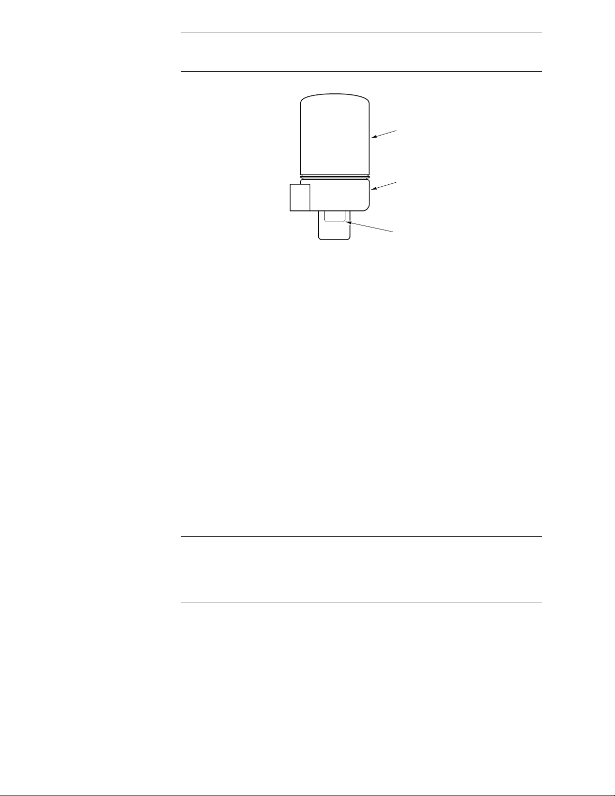
Housing
Base
Wrench Flats
Figure-4 Housing and Base Location.
Dampers
The actuator i s not posi tion se nsitive. It can be mounte d in any posi tion i n an NEMA Type 1
location.
Valves
Allow 3" (76 mm) of clearance above the actuator val ve assembly for the removal and
reattachment of the actuator to the installed valve.
1. Install all two-way valves so that they close against the flow. An arrow on the valve body
or tag indicates proper flow direction.
2. Always install three-way mixing valves with two inlets and one outlet.
3. Always install three-way diverting valves with one inlet and two outlets.
4. Fo r steam applications only, mo unt the actuator above the valve body at 45° from
vertical.
5. Ac tuators can be mounted in any upright position above the centerline of the valve
body.
Wiring Requirements Contr ol Leads
The control leads may be connected to a Class 2 circuit if routed separately from Class 1
circuit wiring. Refer to Figure-9 .
Caution:
• Use either 18 gage, two- or three-conductor twisted, shielded wire when it becomes
necessary t o instal l the control le ads in t he same c onduit wi th power wiring or wh en high
RFI/EMI generating devices are near.
• Do not connect the shield to earth ground or any other leads.
135 Ω Slidewire Controller: Use 18 gage, three-conductor, twisted leads (TAC Part
Number W-103 or equivalent) for runs of up to 500 ft. (152 m) between the 135 Ω slidewire
controller and the actuator. Use larger-gage wires for longer runs.
4 to 20 mAdc Controller: Use 18 gage, two-conductor , twisted leads (TAC Part Number
W-102 or equivalent) for runs of up to 500 ft. (152 m) between the 4 to 20 mAdc controller
and the actuator . Use la rger-gage wires for longer runs.
Power Leads
The low voltage (24 Vac) actuators may be connected to a Class 2 ci rcuit.
Line volt age (12 0 Vac an d 240 Vac ) power l eads m ust b e c onnected to a Cl ass 1 cir cuit and
routed separately from Class 2 circuit wiring. Refer to Figure-9 .
6 © Copyright 2008 TAC All Rights Reserved. F-23576-6
Page 7
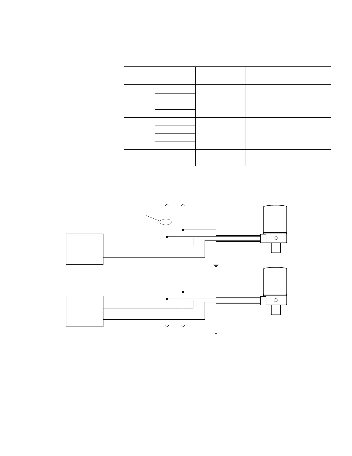
Refer to Table-4 for the maximum length of run for the power leads, for the given wire
size(s). To determine the allowable maximum power lead run when wiring multiple
actuators, divi de the maxi mum ru n shown in Tabl e-4 by t he nu mber of ac tua tors on the run .
Refer to
Figure-5 for further det ails.
Table-4 Power Wiring Data.
Actuator
Voltage
Vac
24
120
240
*Green grounding wire is provided. Length is 4 ft. (1.2 m).
Actuator Model
Number
MPR-5613
MPR-5713
MPR-5633
MPR-5733
MPR-5610
MPR-5710
MPR-5630
MPR-5730
MPR-5611
MPR-5711
Power Lead Colors* Wire Size GA
Black/Blue & Black
White & Black 14 3,500 (1,067)
White/Black & Black 14 6,00 0 (1,829)
14 300 (91.5)
12 480 (146.3)
Max. Two-Wire Run ft.
(m)
To AC Power
Source
24Vac Black/Blue
120Vac White
Controller
Controller
240Vac White/Black
Yellow/White
Red
Blue
Yellow/White
Red
Blue
To Additional MPR-56XX and
MPR-57XX Series Actuators
Black
Green
Green
MPR-56XX or MPR-57XX
MPR-56XX or MPR-57XX
Figure-5 Wiring of Multiple MPR-56XX and MPR-57XX Series Actuators to a Single Power Source.
Wiring Connections General
Make connections as required. Refer to the following sections:
• Wire Lead Connectio ns (No Conduit)
• Install 3/8" reduced (thin wall) flexible conduit onto either side of actuator
• Install 3/8" reduced (thin wall) flexible conduit directly onto actuator
• Install conduit box onto actuator
F-23576-6 © Copyright 2008 TAC All Rights Reserved. 7
Page 8
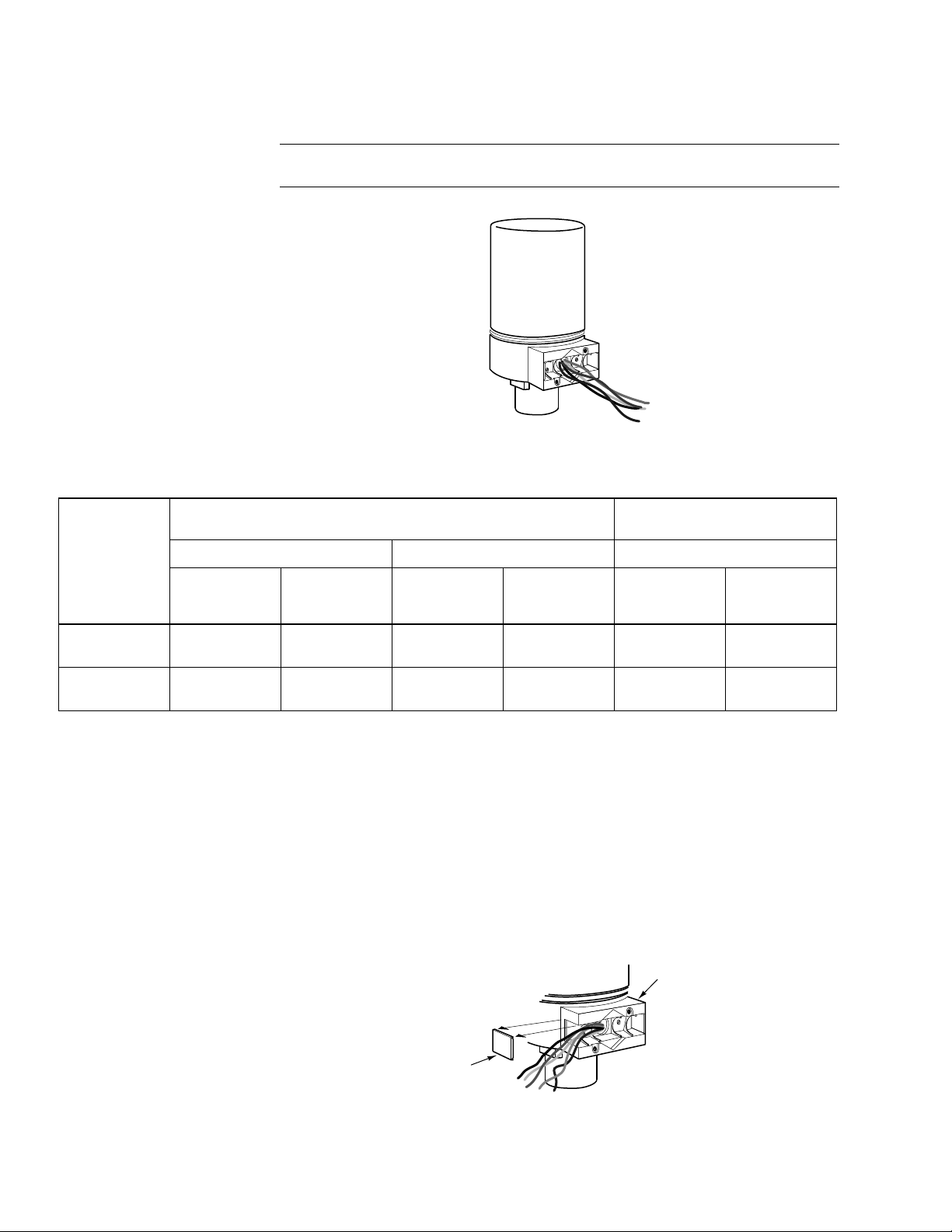
Wire Lead Connections (No Conduit)
Make connections as required. Refer to Figure-1 through Figure-3 to determine your
particular application. Refer to Table-5 to determine the damper position versus the input
signal. Refer to Fi gure-6 for a view of the actuator.
Note:
The cover plate and scr ew supplied with the actuator are not required with this
method.
Table-5 Damper Position Versus Input Signal.
Figure-6 Connection of Wire Leads (No Conduit).
Damper Normal
Position
Normally
Open
Normally
Closed
Decrease
In "R" to "B"
Resistance
Closes
Damper
Opens
Damper
135 Ω Slidewire (Series 90) Input Signal
Figure-1 Figure-2 Figure-3
MPR-573X Series
Decrease
In "R" to "W"
Resistance
Opens
Damper
Closes
Damper
Decrease
In "R" to "B"
Resistance
Opens
Damper
Closes
Damper
Decrease
In "R" to "W"
Resistance
Closes
Damper
Opens
Damper
MPR-563X Series
4 to 20 mA Input Signal
Decrease
In mA Signal
Opens
Damper
Closes
Damper
Increase
In mA Sign al
Closes
Damper
Opens
Damper
Installing 3/8" Reduced (thin) Wall Flexible Conduit onto One or Both Sides
of Actuato r
Flexible cond uit may be installed onto one or bot h sides of the actuator (ref er t o Figure-8
and Figure-9 ). Inst all each conduit as follows:
1. Determine the side of the actuator to which the flexible conduit is to be attached.
2. Remove the knockout, using channel lock pliers, on the sel ected side of the actuator.
Refer to Figure-7 .
3. Make the required connections. Refer to Figure-1 , Figure-2 , and Figure-3 to
determine your particular applica tion. Refer to Table -5 to determine the damper position
versus the input signal.
Base
Knockout
Figure-7 Removal of Knockout on Actuator Base.
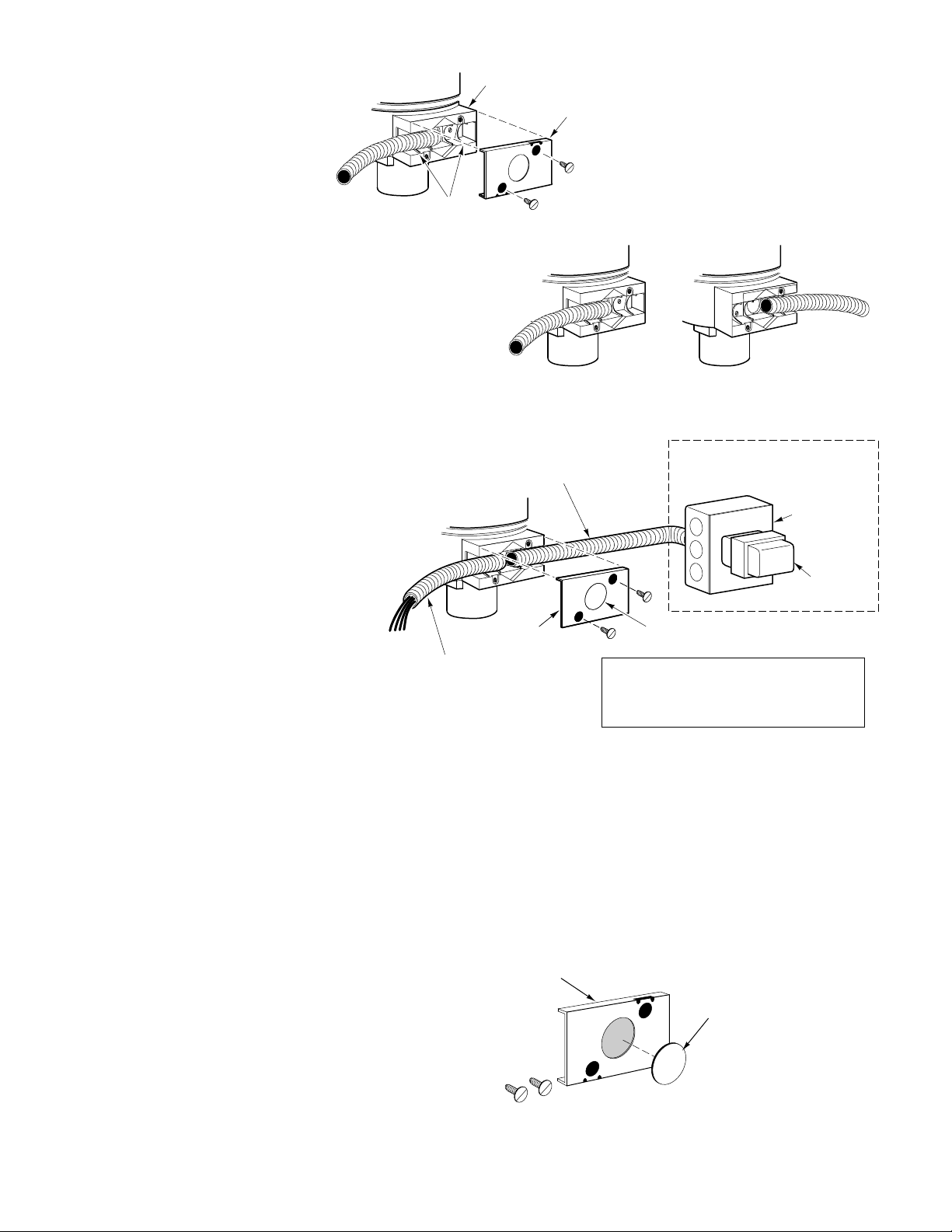
4. Slip the conduit onto the base, over the ri bs. Refer to Figure-8 and Figure-9 .
8 © Copyright 2008 TAC All Rights Reserved. F-23576-6
Page 9
Base
Cover Plate
Ribs
or
Figure-8 Flexible Conduit Installation to Either Side of Actuator.
Line voltage motor leads when
connected to circuits other than
Class 2.
Cover Plate
The low voltage control leads may
be connected to a Class 2 circuit
if routed separately from the line
voltage circuit wiring.
Leave Knockout in place
Note: Class 2 circuit wiring must be routed
separately from the wiring from other circuits.
Do not route Class 2 circuit wiring in the same
conduit box with the line voltage transformer
Typical for 24 Vac models
(MPR-56X3 and MPR-57X3)
4 x 4
Conduit
Box
Transformer
(AM-610 shown)
Figure-9 MPR-5600 and MPR-5700 Series Wiring with Separation for
Class 2 and Line Voltage Circuits.
5. Install the cover plate with two screws. The cover plate and two screws are supplied
with the actuator.
6. If flexible conduit is to be insta ll ed on both sides of the actuator, repeat the preceding
steps to insta ll the second conduit.
Installing 3/8" Reduced (thin) Wall Flexible Conduit Directly onto Actuator
1. Remove the knockout from the cover plate supplied with the actuator. Refer to Figure10 .
Cover Plate
Knockout
Figure-10 Cover Plate Knockout Removal.
F-23576-6 © Copyright 2008 TAC All Rights Reserved. 9
Page 10
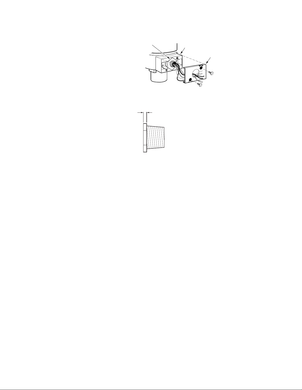
2. Slip the leads through a standard 1/ 2" condu it bushi ng (not suppli ed) and the knocko ut
hole in the cover plat e. Refer to Figure-11 and Figure-12 .
1/2" Conduit Bushing
(not supplied)
Base
Cover Plate
Figure-11 Conduit Bushing and Cover Plate Installation.
1/8" maximum
Use TAC 11-1612,
Bridgeport 1102-DC,
or equivalent
Figure-12 1/2" Conduit Bushing.
3. Nest the conduit bushing in the base.
4. Install the cover plate, using the two screws provided.
5. Make the required connectio ns. Refer t o Figure-1 through Figur e-3 to determine yo ur
particular application. Refer to Table-5 to determine the damper position versus the
input signal.
6. Attach the flexible conduit to the conduit bushing, as required.
Installing Conduit Box onto Actuator
1. Remove the knockout from the cover plate supplied with the actuator. Refer to Figure10 .
2. Slip the leads through a standard 1/ 2" condu it bushi ng (not suppli ed) and the knocko ut
hole in the cover plat e. Refer to Figure-11 and Figure-12 .
3. Nest the conduit bushing in the base.
4. Install the cover plate, using the two screws provided.
5. Attach the conduit box to the threaded adaptor.
6. Make the required connectio ns. Refer t o Figure-1 through Figur e-3 to determine yo ur
particular application. Refer to Table-5 to determine the damper position versus the
input signal.
7. Install the rigid condu it, the f lexib le cond uit, etc. to the c onduit box as req uired. Refer t o
Figure-13 .
10 © Copyright 2008 TAC All Rights Reserved. F-23576-6
Page 11
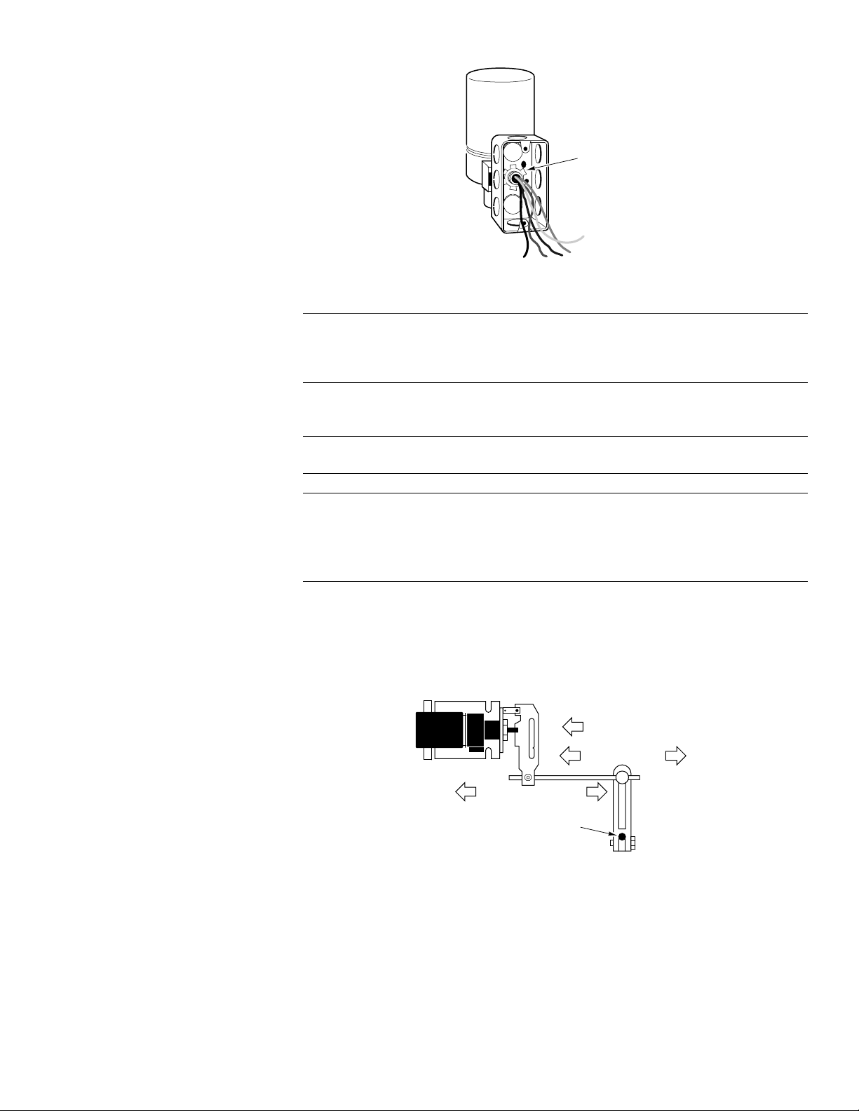
Note:
As shown in Figure- 11 , the hole in the cov er plat e of the ac tua tor condu it hous ing is
sized to a ccept both Brit ish st and ard M20 ( 20mm) conduit con nect ors an d 20 mm-to-PG16
adaptors for use with DIN PG16 connectors. (Follow the s teps for install ing the conduit box
to the actuator.)
Linkage Assembly Damper
Note:
Each actuator in the MPR-5X3X series is provided with a factory-installed damp er
linkage. No separately-ordered linkage is required.
Caution:
• Do not twist or exert any force on the actuator housing during installation. Either turn
the base by hand or, if necessar y, use a 1-5/8" open-ended wrench (TOOL-37) on the
flats provided on the actuator base, or on the val ve body mounting nut. (Refer to
Figure-4 )
Conduit Lock Nut
Figure-13 Attachment of Conduit Box to Thr eaded Adaptor.
1. Determine the best mounting position for the actuator as follows:
a. Determine, from the system requir ements, if the damp er should spring- return to the
open position (Figure-14 ) or closed position (Figure-15 ) whenever power is lost
to the actuat or. An actuator is normally linked so as to retract (spring-return) to the
damper’s fully open position (heat position).
Spring returns open
on loss of power
Open
ExtendRetract
Damper Shaft
Close
Figure-14 Dampers Open When Actuator Retracts
(Spring-Returns Open on Power Loss).
F-23576-6 © Copyright 2008 TAC All Rights Reserved. 11
Page 12
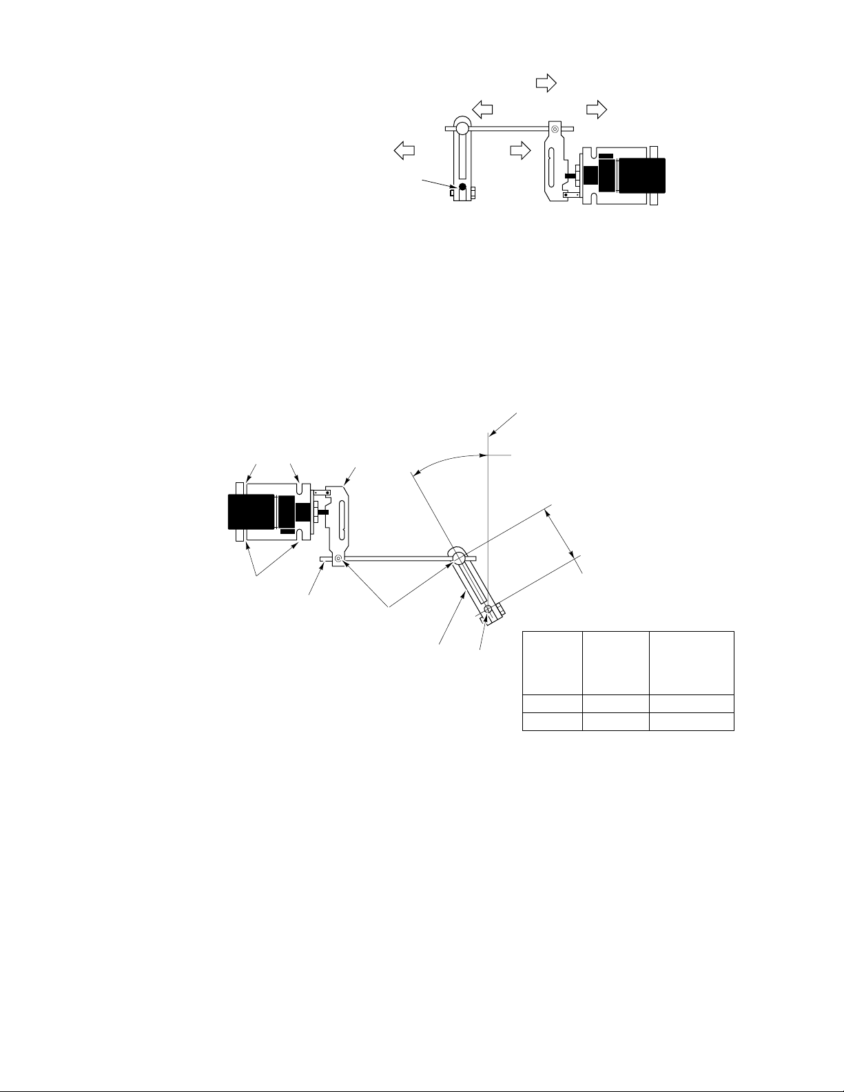
Spring returns open
on loss of power
Retract Extend
Open
Damper Shaft
Close
Figure-15 Dampers Open When Actuator Extends
(Spring-Returns Closed on Power Loss).
b. Be sure to allow adequat e working space around the actuator mounting location to
mount the actuator, li nk it to the damper, and wire it into the system (refer to
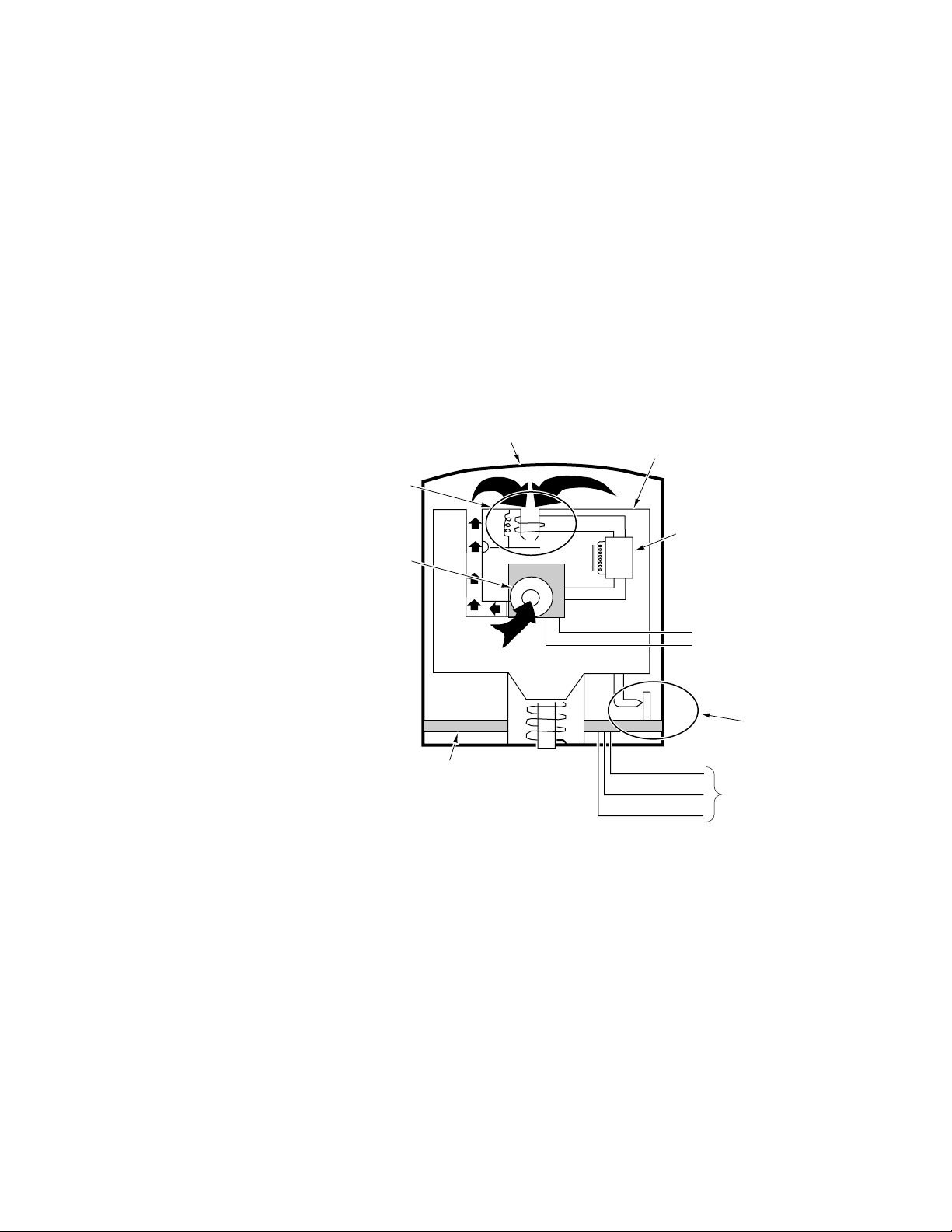
Figure-21 ).
c. If possible, select a mounting position such that, at mid-stroke, the actuator crank
arm and the damper crank arm on the drive shaft are each at a 90° angle to th e
damper rod (refer to Figur e-16 ). This is the recommended mounti ng position. It
may be necessary to swivel the actuator linkage to arrive at this mounting location.
Mid-Stroke Position
Mounting
Points
Actuator
Crank Arm
Angle from Mid-Stroke
Position (See Table)
Mounting
Points
Damper
Rod
Linkage
Connectors
Damper
Crank Arm
Damper
Shaft
Required
Damper
Rotation
Position of Linkage
Connector (See Table)
Angle
from
Mid-Stroke
Position
60°
90°
30°
45°
Position of
Linkage
Connector
2" (50 mm)
1-1/2" (38 mm)
Figure-16 Recommended Actuator/Damper Mounting.
d. Consider the damper rod length when positio ning the actuator in relation to the
damper. A damper rod that is too l ong is not rigid enough to provide good control,
while a damper rod that is too sh ort mak es adjustment difficul t.
2. Position the actuator on the duct and mark the location of the mounting holes, usi ng the
actuator mounti ng bracket as a template (refer to Figure-21 ).
3. Drill or punch the mounting holes in the duct for the appropriate 1/4" diameter screws
or bolts. The actuator must be mounted firmly enough to prevent excessive actuator
movement under nor mal damper l oading. If ther e is exces sive act uator movem ent, the
damper may not fully open or close.
4. Mount a ball joint connector in the slot on the damper crank arm. To achieve 9 0° of
damper rotatio n, position the connector 1-1/2" (38 mm) from the centerline of the shaft
hole on the crank arm. For 60° of damper rotation, positio n the connector 2" (50 mm)
from the shaft hole centerline. Typical ly, 60° to 70° of rotation (maximum is 90°) is
sufficient to permit almost maximum air flow t hrough the damper s. Refer to Figure-16 .
12 © Copyright 2008 TAC All Rights Reserved. F-23576-6
Page 13

5. Rotate the damper to its open position. Install and secure the damper crank arm (with
ball joint connector) to the damper shaft, positioning the crank arm as follows (refer
to Figure-16 ):
a. To achieve 60° of damper rotation, position the crank arm so that it is pointed
towards the actuator at 30° from its mid-stroke position.
b. To achieve 90° of damper rotation, position the crank arm so that it is pointed
towards the actuator at 45° from its mid-stroke position.
6. Install the damper rod by sliding one end through the ball joint conn ector mounted on
the damper crank ar m, and the othe r end through t he straigh t connector on the actuat or
crank arm. Tighten the nut on the actuator crank arm’s straight connector. Cut off any
excess length of damper rod.
7. For normally open dampers, tighten the nut on the ball joint connector on the damper
crank arm. To ensur e that the damper cl oses complet ely, make adjustments so that the
actuator is 1/16" (1.6 m m) from the extended end of stroke when the damper closes.
Verify and, if necessary, make final adjustments during system checkout.
8. For normally closed dam pers, rotate the dam per crank arm until the damper is closed.
While holding the damper closed, tighten the nut on the ball joint connector on the
damper crank arm. To ensur e that the d amper closes c ompletely, make adjust ments so
that the actuator is 1/16" (1.6 mm) from the retracted end of stroke when the damper
closes.
Final adjustment of the actuator and damper must be performed when the system is
powered and functioning. Refer to the CHECKOUT section to ensure that the damper is
linked correctly.
Valve
For valve assembly details refer to AV-600 Hydraulic Actuat or Valve Linkage Kit, F26279 or AV-601 Linkage Extension Set for AV- 600 Valve Linkage Ki t, F-26280. Refer to
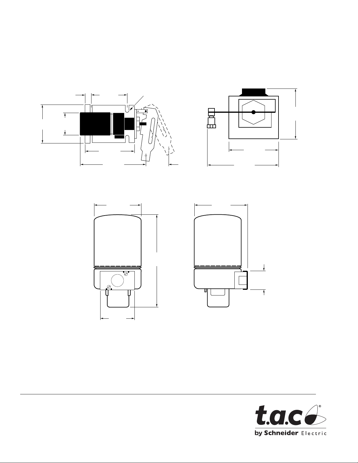
Figure-22 for external dimensions of the valve actuator.
CHECKOUT
Positioning with
Controller
Go, No-Go Test
(MPR-57XX Series
Only)
Manual Positioning
(MPR-57XX Series
Only)
After the entire system has been installed and the actuator has been powere d up, per form
the following checks for proper system oper ation.
Caution:
If the sensed media is within the controller’s se tpoint range, the actuator can be posit ioned
by adjusti ng the cont roller setpoi nt up and down. Check f or correc t oper ation of th e ac tuator
(valve or damper) while the actuator is being stroked.
1. Apply power to the actuator.
2. Disconnect the actuator’s control leads from the contr oll er.
3. Make the actuator shaft extend fully by shorting the red lead to the bl ue lead.
4. Make the actuator shaft retract fully by shorting the re d lead to the yellow/white lead.
5. Check for proper operation of the valv e or damper as the actuator is operat ed.
6. Reconnect the actuator wires to the controller.
7. Remove power from the actuator.
1. Apply power to the actuator.
2. Disconnect the actuator’s control leads from the contr oll er.
3. Attach the slidewire l eads fr om t he cali brat ion box (TOOL- 209) t o the s ame-c olor l eads
4. Manually position the actuator by turning the knob of the calibration box (TOOL-209).
5. Check for proper operation of the valv e or damper as the actuator is operat ed.
Never power the actuator without a spring return linkage attached.
on the actuator.
Turning the knob in the cl ockwise dire ction retract s the actuator shaf t. Turning the knob
in the counterc lockwise direction ext ends the actuator shaft.
F-23576-6 © Copyright 2008 TAC All Rights Reserved. 13
Page 14
THEORY OF OPERATION
6. Reconnect the actuator wires to the controller.
7. Remove power from the actuator.
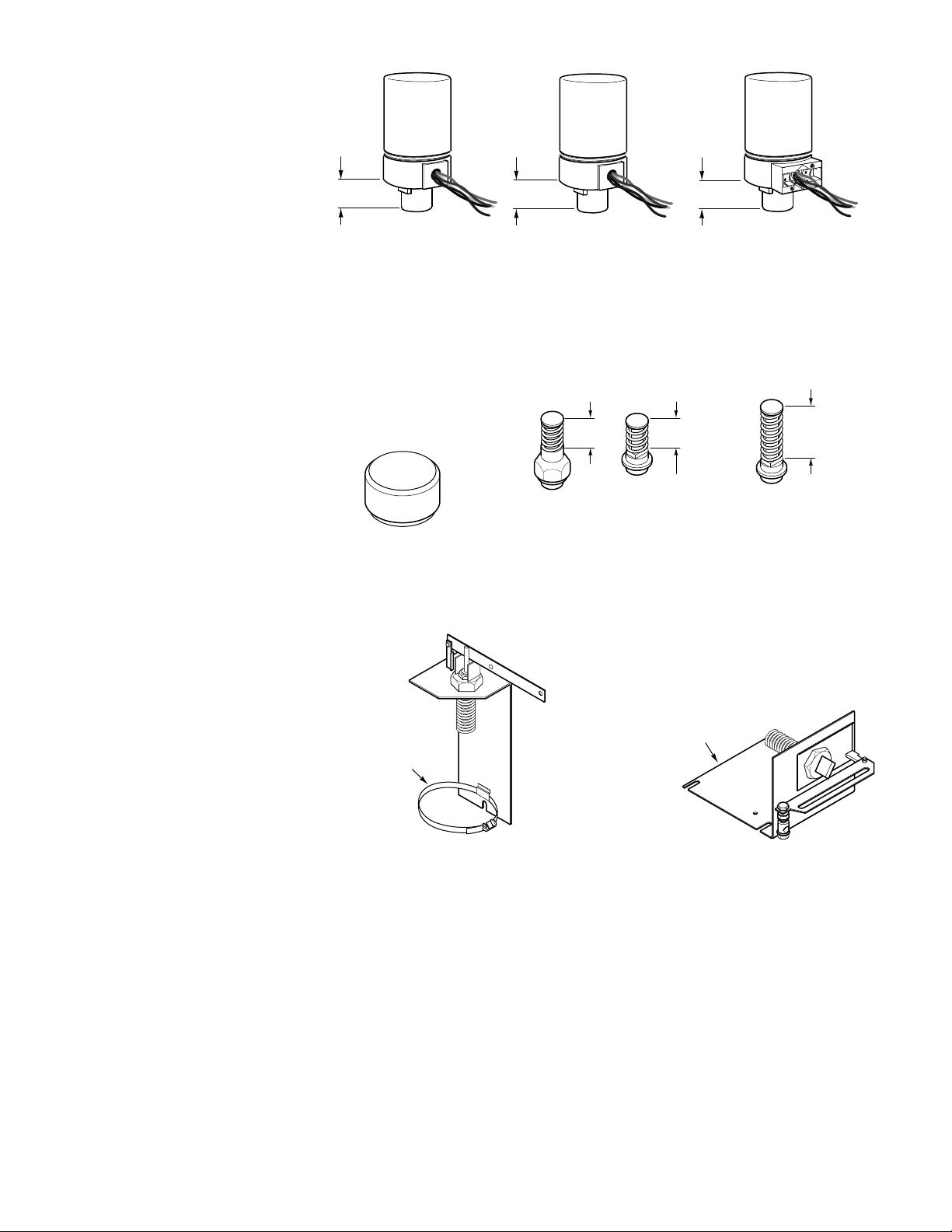
Refer to Figure-17 . The permanently sealed, oil-filled case contains a movable hydraulic
piston assembly and an electric pump/motor for the hydraulic system. The electric
pump/motor is powered by t he in put supply voltage and runs con tinuously , generat ing a flui d
pressure whi ch is transm it ted to the t op o f the pist on. Thi s fl uid pr essu re cre ate s a hydr aul ic
force which drives the piston downward. Opposing the hydraulic force is the spr ing of the
valve or damper linka ge. When the hydraul ic for ce becom es great eno ugh to overc ome the
opposing spri ng force, the piston transl ates downward, extending the output shaft.
The pump/motor contai ns a transformer winding whi ch provides power to the Vdc power
supply. The power supply, in turn, provides power to the transducer assem bly. To
proportionally position the shaft, first the control signal (135 Ω slidewire or the 4 to 20mA)
input is compared to the shaft position feedback signal, through the actuator controller
circuit. Then , the actuat or controll er circuit emi ts an output signal whi ch positions t he flapper
in the transduc er. The flappe r opens or closes further to decr ease o r increase th e hydr aulic
pressure above the piston, resulting in an upward or downward movement at the shaf t.
Oil-Filled Case
Transducer
Assembly
Electric
Motor/Pump
Controller Printed
Circuit Board
Hydraulic Piston
Assembly
Yellow/White
Figure-17 MPR-56XX and MPR-57XX Series Actuators.
Red
Blue
Vdc Power
Supply
To AC Power
Source
Feedback
Controller
Input
REPLACEMENT PARTS
The installati on of repl acement act uators , in place of the obsolete ser ies of MPR-56 XX and
MPR-57XX actuators (refer to Figure-18 ), may require additional it ems. These replace ment
items are required f or the following reasons:
1. The AM-601 damper linkage is used to convert base actuators to damper actuators when
damper models are not available.
2. The AM-602 spacer is used wh en current actuato rs are installed on old linkages (refer
to Figure-19 and Figure-20 ).
3. The AE-249 transformer (208 Vac to 120 Vac) is used when replacing 208 Vac
actuators (MPR-5XX2) with 120 Vac actuators (MPR-5XX0).
14 © Copyright 2008 TAC All Rights Reserved. F-23576-6
Page 15
3/4"
(19 mm)
MPR-561X and MPR-571X MPR-561X-2 and MPR-571X-2 MPR-561X-3 and MPR-571X-3
Obsolete Actuators
1-5/16"
(33 mm)
1-5/16"
(33 mm)
Current Actuator
Figure-18 Current and Obsol ete Actuators
.
2-3/16"
(56mm approx.)
Current Linkage
AV-600
Spacer
AM-602
1-5/8"
(41mm approx.)
1-5/8"
(41mm approx.)
Obsolete Linkages
AV-315, AV-317, AV-319-10,
& AV-319-20
MAINTENANCE
TROUBLESHOOTING
Figure-19 Spacer and Curre nt and Obsolete Valve Linkages.
No Strap
Strap
Obsolete AM-601
Current AM-601-0-0-2
Figure-20 Current and Obsol ete Damper Linkages.
The actuator is sealed in oil and requires no maintenance.
Regular maintenance of the total system is recomm ended to assure sustained, optimum
performance.
Use the following steps to locate malfuncti ons:
1. Check the controller and determine that it is operating to the manufacturer’s
specifications.
2. The actuator motor should run continually. If it does not run, check the supply voltage
and the actuator wiring.
F-23576-6 © Copyright 2008 TAC All Rights Reserved. 15
Page 16
FIELD REPAIR
DIMENSIONAL DATA
3. Verify actuator operation, using the Go, No-Go Test. If the actua tor does not function,
replace it with a functi onal unit.
None. Replace an inoperative actuator with a functi onal unit.
4-1/4"
(108 mm)
5/16"
(8 mm)
3-1/4"
(83 mm)
(117 mm)
Actuator
(146 mm)
4-5/8"
5-3/4"
8"
(203 mm)
(4) 1/4"
(6 mm)
2"
(50 mm)
Figure-21 Damper Linkage Assembly Dimensions.
3-1/4" Dia.
(83 mm)
6-3/4"
(171 mm)
4-3/4"
(120 mm)
4-1/4"
(110 mm)
5-1/2"
(140 mm)
3-23/32"
(94 mm)
Copyright 2008, TAC
All brand names, trademarks and registered
trademarks are the property of their respective
owners. Information contained within this
document is subject to change without notice.
F-23576-6
2-9/32"
(58 mm)
Figure-22 Actuator Dimensions.
TAC
1354 Clifford Avenue
P.O. Box 2940
Loves Park, IL 61132-2940
www.tac.com
1-3/8"
(35 mm)
 Loading...