

Page 1
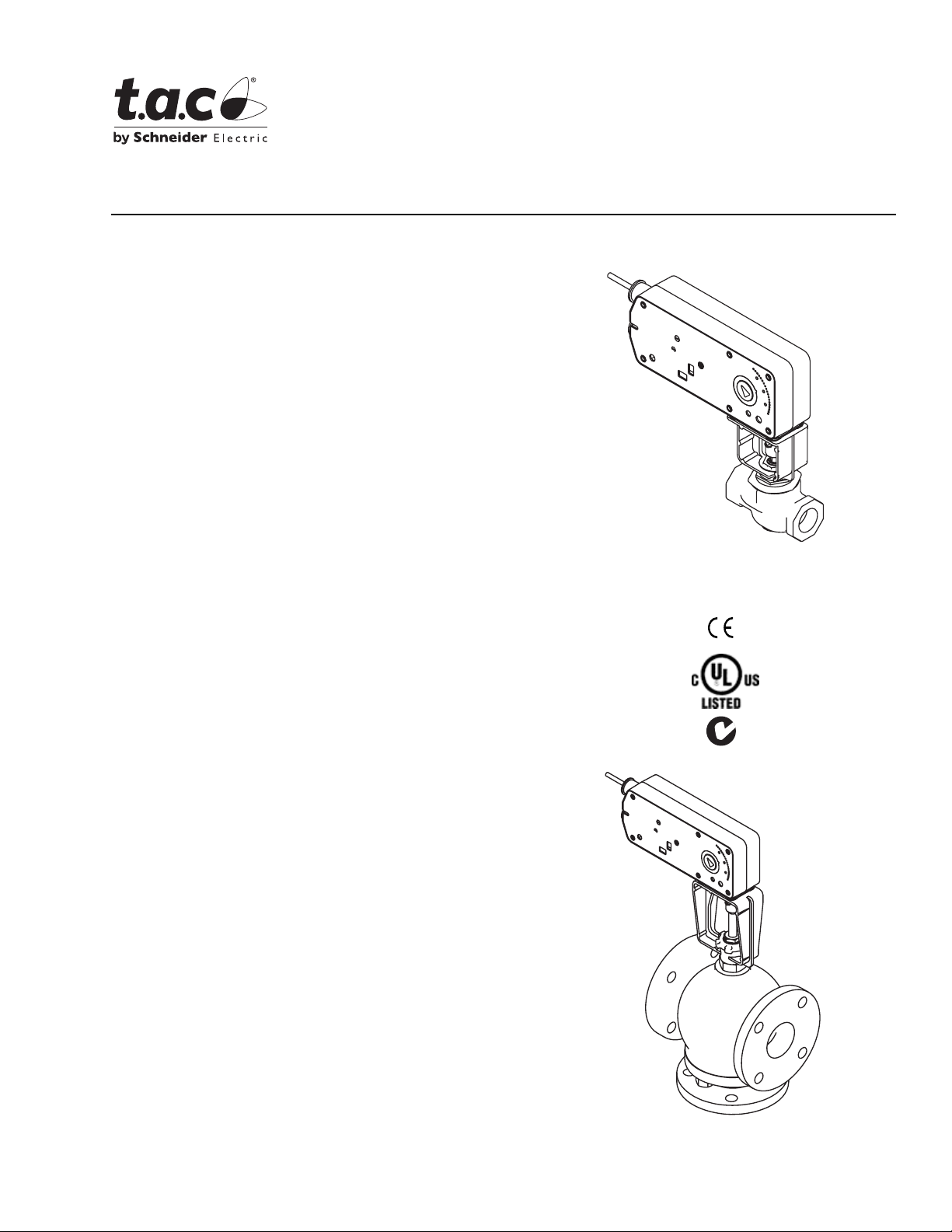
Application
TAC DuraDrive Linear Actuators are designed to
mount directly onto two-way or three-way valves. They
provide linear travel to economica lly operate 1-1/4" to
2" VB-7xxx, 2-1/2 ” to 5" VB-8xxx, 2-1/2" to 4" VB-9 31x,
and discontinued 1-1/2” to 4” VB-9xxx valves in hot
water, chilled water, and steam applications up to
366°F (186°C) fluid temperature.
The linear spring return actuators provide either two
position, floating or proportional modulation control
(depending on model selection) of valves in HVAC
systems.
MAx1-720x Two Position Series
MFx1-72 03 Floati ng Series
MSx1-7203 Proportional Series
TAC DuraDrive™ Linear Series
Spring Retur n Actu ato r
General Instructions
Features
• Two position models controlled by SPST controller
• Floating models controlled by SPDT floating
controllers
• Proportional models controlled by 2-10 Vdc, or 4-20
mAdc with the addition of a 500 ohm resistor.
Control function direct/reverse action is switch
selectable
• 220 lb force (979 newton) with 1/2” (13 mm) or
1" (25 mm) nominal linear stroke
• Automatically sets control signal input span to match
valve travel
• 24 Vac, 120 Vac, and 230 Vac models
• Rugged die-cast enclosures rated for NEMA 2, UL
Type 2/IP54
• Overload protection throughout stroke
• Compact size for applic ation flexibility
• Manual override to allow positioning of valve and
preload
Mx51-720x
• Integral linkage for direct mount to valves
• Five year warranty
Mx61-720x
Printed in U.S.A. 8-08 © Copyright 2008 TAC All Rights Reserved. F-27120-5
Page 2

Applicable Literature
• TAC DuraDrive Linear Series Spring Return Actuator Submittal Sheet, F-27165
• Two-Way and Three- Way Globe Valve Assemblies with TAC DuraDri ve Linear Series Spring Return Actuators Submitta l Sheet, F-27167
• EN-205 Water System Guidelines, F-26080
• Vx-7xxx, Vx-9xxx Series Linked Globe Valves with TAC DuraDrive Linear Series Actuators Selection Guide, F-27252
• Vx-8xxx Valve Selection Guide, F-27199
• AM-731, AM-732, AM-733, AM-734, Kit General Instructions, F-27203
• VB-7213 Series 1/2" to 2" Screwed NPT, Stem Up Open, Two-Way Valves, General Instructions, F-26075
• VB-72 14 Series 1/2" to 2" Union Sweat, Solder Joint Stem Up Open, Two-Way Valves, General Instructions, F-25675
• VB-7215 Series 15 mm to 50 mm Screw ed Rp, Stem Up Open, Two-Way Valves, General Instructions , F-26077
• VB-7223 Series 1/2" to 2" Screwed NPT, Stem Up Close d, Two-Way Va lves, General Instructions, F-26073
• VB-7224 Series 1/2" to 2" Union Sweat, Solder Joint Stem Up Closed, Two-Way Valves, General Instructions, F-243 87
• VB-7225 Series 15 mm to 50 mm Screwed Rp, Stem Up Closed, Tw o-Way Valves, Ge neral Instruction s , F-26079
• VB-7253 Series 1/ 2" to 2" Screwed NPT, Stainless Steel Trim with Teflon Disc, Stem Up Open, Two-Way Valves, General Instructions,
F-24388
• VB-7263 Series 1/2" to 2" Screwed NPT, Stainless Steel Trim with Teflon Disc, Stem Up Closed, Two-Way Valves, General Instructions,
F-24389
• VB-72 73 Series 1/ 2" to 2" Screwed NPT, Stainless St eel Trim, Stem Up Open, Two-Way Valves, General Instruct ions, F-24390
• VB-7283 Series 1/2" to 2" Screwed NPT, Stainless Steel Trim, Stem Up Closed, Two-Way Valves, General Instructions, F-24391
• VB-7313 Series 1/2" to 2" Screwed NPT, Three-Way Mixing Valves, General Instructions, F-26074
• VB-7314 Series 1/ 2" to 2" Union Sweat, Sol der Joint, Three-Way Mixing Valves, General Instructions, F-24394
• VB-73 15 Series 15 mm to 50 mm Screwed Rp, Three-Way Mix ing Valves, General Inst ructions, F-260 78
• VB-73 23 Series 1/2” to 2” Screwed NPT Three-way Diverting Valves, General Instruction, F-26076
• VB-82 13 Series 2-1/2” to 6" Flanged, S tem Up Open, Two-Way Valves, General Instructions, F -27193
• VB-82 23 Series 2-1/2” to 6" Flanged, Stem Up Closed Two-Way Val ves, General Instructions, F-27194
• VB-8303 Series 2-1/2” to 6" Flanged, Three-Way Diverting/Mixing Valves, General Instructions, F-27197
• VB-9213 Series, 2-1/2” and 3” Screwed NPT, 2-1/2” to 6” 125 Lb. Flanged, Stem Down to Close Two-Way Valves, General Instructions,
F-24382
• VB-9 21 5 Ser i es , 65 mm and 80 mm Scr ew e d R
• VB-9223 Series, 2-1/2” and 3” Screwed NPT, 2-1/2” to 6” 125 Lb. Flanged, Stem Up to Close Two-Way Valves, General Instructions,
F-24386
• VB-9 22 5 Ser i es , 65 mm and 80 mm Scr ew e d R
• VB-93 13 Series, 2-1/2” and 3” Screwed NPT, 2-1/2” to 6” 125 Lb. Flanged, Three-Way Mixing Valves, General Instructions, F- 24393
• VB-9 31 5 Ser i es , 65 mm and 80 mm Scr ew e d R
, Stem Down to Close Tw o-Way Valves, General Instructions, F-25672
p
, Stem Up to Close Two-Way Valves, General Instructions, F-25673
p
, Three-Way Mixing Va lves, General Instructions, F-25674
p
2 © Copyright 2008 TAC All Rights Reserved. F-27120-5
Page 3

SPECIFICATIONS
a
Actuator In puts
Control Signal: MAx1-720x—On-off spring return, SPST control contacts or Triacs
(500mA rated). MFx1-7203—Floating point , SPDT cont rol contact s or T riacs (500 m A rated)
24 Vac. MSx1-7203—Proportional, 2 to 10 Vdc or 4 to 20 mAdc with 500 Ω resistor.
Power Input: MAx1-720x—24 Vac ± 20%, 22 to 30 Vdc, 120 Vac ± 10%, 230 Vac ± 10%,
50/60 Hz. All 24 Vac circuits are Class 2. All circuits 30 Vac and above are Class 1.
MFx1-7203, MSx1-7203— 24 Vac ± 20%, Class 2, 22 to 30 Vdc.
Connections: 3 ft (91 cm) appliance ca bles, 1/2 inch ( 13 mm) conduit connecto rs. For M20
Metric condui t, use AM-756 adaptor.
Actuator Outputs
Electrical:
Position Feedback Vol tage (proportional only):
MSx1-7203—2 to 10 Vdc (max. 0.5 mA) output signal for position feedback or to
operate up to four additional slave actuators.
Mechanical:
Motor Type: Brushless DC.
Linear Stroke (Nominal): Mx51-720x—1/2" (13 mm). Mx61-720x—1” (25 mm).
Approx. Stroke Timing, 100 seconds for 1/2" stroke. 190 seconds for 1” stroke.
Manual Override, Allows positioning of valve and preload using manual crank.
Right/Left Switch, Permits rever se acting/direct acting linear motion (MSx1 only).
Environment:
Ambient Temperature Limi ts,
Shipping & Storage, -4 0 to 160 °F ( - 40 to 71 °C ).
Operating, 0 to 140 °F (-18 to 60 °C).
Temperature Restrictions,
Actuator
Mx51-720x
Mx61-720x 140 °F (60 °C)@ 300 °F (149 °C) 2-1/2" to 4" VB-931x
Mx61-720x 140 °F (60 °C)@ 281 °F (138 °C)
Discontinued
Max. Allowable Ambient
@ Max. Fluid Temperatures
Valve Body
140 °F (60 °C)@ 281 °F (138 °C) VB-721x, 722x
120 °F (49 °C)@ 300 °F (149 °C) VB-7 3xx
100 °F (38 °C)@ 340 °F (171 °C) VB-725x, 726x
90 °F (32 °C)@ 366 °F (186 °C) VB-727x, 728x
2-1/2” to 5” VB-8xx3,
2-1/2" to 4" VB-92xx
a
Humidity: 15 to 95% RH, non-condensing.
Location:
NEMA1. NEMA 2, UL Type 2 (IEC IP54) with customer suppl ied watertight conduit
connectors.
Agency Listings
UL 873: Underwriters Laboratories (File #E9429 Category Temperature-Indicating and
Regulating Equipment).
CUL: UL Listed for use in Canada by Underwriters Laboratories. Canadian Standards
C22.2 No. 24-93.
European Community: EMC Directive (89/336/EEC). Low Voltage Directive (72/23/EEC)
Australia: This produc t meets requir ements to bear the C-Tick Mar k accordi ng to the te rms
specified by the Com mu nications Authority under the Radiocommunications Act 1992.
The specifica tions conform to acc eptabl e industr y standar ds. For applicat ions at condi tions
beyond these specif icat ions, con sult your loca l TAC represen tati ve offi ce. TAC shall not be
liable for dama ges resulting from misappl ication or misuse of its products.
F-27120-5 © Copyright 2008 TAC All Rights Reserved. 3
Page 4

Table-1 Specifications.
Approximate
Stroke Timing in
Seconds @ 70°F
(21°C)
Powered
Spring
Return
Part
Number
Control
Action
Voltage
Actuator Power Input
Running Holding
50 Hz 60 Hz
VA W VA W W
Amps
DC
50/60
Hz
Linear
Stroke
Inches
24Vac
MA51-7203
±20%
9.8 7.5 9.7 7.5 .29 2.8
22-30 Vdc
MA51-7200
MA51-7201
MA61-7203
2
Position
120 Vac
±10%
230 Vac
±10%
24 Vac
±20%
11.7 8.8 10.0 8.4 N/A 3.6/5.0
15.5 9.5 10.6 8.5 N/A 4.6/3.3
9.8 7.5 9.7 7.5 .29 2.8
5/8 <100 <35
22-30 Vdc
MA61-7200
MA61-7201
120 Vac
±10%
230 Vac
±10%
11.7 8.8 10.0 8.4 N/A 3.6/5.0
15.5 9.5 10.6 8.5 N/A 4.6/3.3
1-1/16 <190 <40
24 Vac
MF51-7203
Floating
MF61-7203
±20%
22-30 Vdc
24 Vac
±20%
9.8 7.7 9.7 7.7 .30 3.3 5/8 <100 <35 1-1/4" to 2"
9.8 7.7 9.7 7.7 .30 3.3 1-1/16 <190 <40
22-30 Vdc
24 Vac
MS51-7203
Proportional
MS61-7203
±20%
22-30 Vdc
24 Vac
±20%
9.8 7.4 9.7 7.4 .28 2.9 5/8 <100 <35 1-1/4" to 2"
9.8 7.4 9.7 7.4 .28 2.9 1-1/16 <190 <40
22-30 Vdc
a
Timing was measured with no load applied to the actuator.
b
Current VB-7xxx series valves and discontinued 1-1/4” VB-9xxx series valves.
c
Current VB-931x Series valves (2-1/2" to 4"), current VB-8xx3 (2-1/2” to 5”) Series valves, and discontinued VB-9xxx (1-1/2" to 4") S eries valves.
a
Output Force
Rating
lb. (Newton)
Min.
220
(979)
Max.
Stall
495
(2202)
Valve
Size
1-1/4" to 2"
2-1/2" to 4"
c
or 5”
2-1/2" to 4"
c
or 5”
2-1/2" to 4"
c
or 5”
b
b
b
ACCESSORIES
AM-763 1/8” Hex crank for manual override
AM-756 Metric conduit adapter M20 x 1.5 to 1/2” NPT
AM-731 Mounting kit - Mx51-720x (stem extension, lock washer, jam nut, and connecting
pin; incl ud ed with actu ato r )
AM-732 Mounting kit - Mx61-720x (stem extension, lock washer, jam nut, and connecting
pin; incl ud ed with actu ato r )
AM-733 Retrofit kit - discontinued VB-9xxx 1-1/2 to 2" valves after 9404 date code
AM-734 Retrofit kit - discontinued VB-9xxx -1/2 to 2" valves prior to 9404 date code
MSx1-7203
AM-703 Input re sc a lin g mo dule, adj us t si gn als to 2-10 Vac , ze r o an d sp an adjust
AM-704 Interface, pulse width modulation (PWM)
AM-705 Positioner (NEMA 4 housing)
AM-706 Min and/or manual positioner for flush panel mount
AM-708 500 Ω resistor for 4 to 20 mAdc control signal
4 © Copyright 2008 TAC All Rights Reserved. F-27120-5
Page 5
Close-Off Pressure and Maximum Operati ng Press ure Differential
For all valve assem blies, be sure to check that the a nti cipated maximum pressure drop
across the valv e in the closed pos iti on will not exceed t he close- off pre ssure rat ing and t hat
the pressure differential across the valve will not exceed the maximum operating pressure
differential rating. For VB-7xxx and VB-9xxx valve applications, consult the Vx-7xxx &
Vx-9xxx Selection Guide, F-27252. For VB-8xx3 valve applications, consult the Vx-8xxx
Selection Guide, F-27199.
TYPICAL TWO POSITION CONTROL (wiring diagrams)
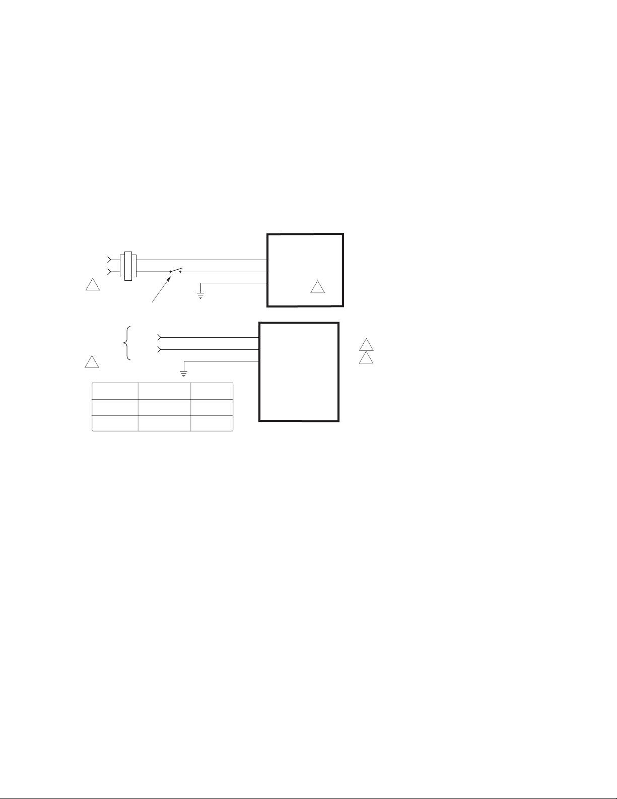
Figure-1 i llustr ate s typi cal wi ring d iagrams for sp ring r et urn MAx1 -720x Series spr ing ret urn
two-position actuators. See Table-1 for model selection.
24 Vac Transformer
or 22-30 Vdc
Line
Volts
1
SPST Control Contact
Blk
Red
Com
Hot (+DC)
Grn/Yel
MA51-7203
MA61-7203
2
120 Vac or
230 Vac
1
Voltage Wire 1 Wire 2
120 Vac White Black
230 Vac Blue Brown
L1 N
L2 H
Wire No. 1
Wire No. 2
Com
Hot
Grn/Yel
MA51-7200
MA51-7201
MA61-7200
MA61-7201
1 Provide overload protection and disconnect as required.
2 Actuators mounted on separate valves may be wired in
parallel. Power supply black wires are connected to the
transformer common and power supply red wires are
connected to the hot lead. Power consumption must be
observed.
Figure-1 Typical Wiring Diagrams for Two Position Actuators.
F-27120-5 © Copyright 2008 TAC All Rights Reserved. 5
Page 6
TYPICAL FLOATING CONTROL (wiring diagrams)
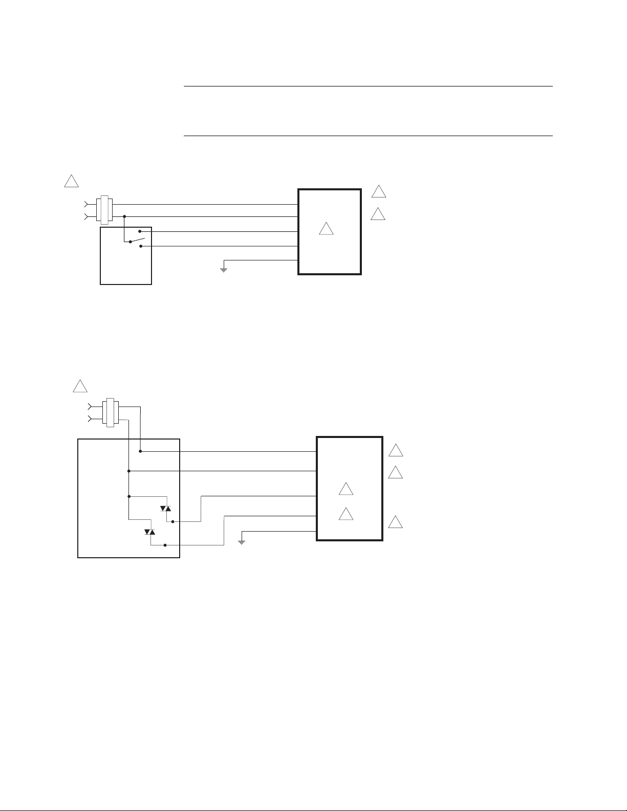
Figure-2 through Figure-5 illustrate typical wiring diagrams for MFx1-7203 Series spring
return floati ng actuators. See Table-1 for mod el selection.
24 Vac Transformer
1
or 22-30 Vdc
Line
Volts
Controller
24 Vac Transformer
1
or 22-30 Vdc
Line
Volts
Typical
Floating
Caution:
This product contains a half-wave rectifier power supply and must not be
powered off transformers used to power other devic es utilizing non-isolated full-wave
rectifier power supplies. Refer to
Common Transformer, F-26363
Black
Red
Blue
Yellow/Black
Common
Hot (+DC)
Extend
Retract
Green/Yellow
EN-206, Guidelines for Power Multiple Devices from a
for detailed information.
MF51-7203
MF61-7203
2
1 Provide overload protection and
disconnect as required.
2 Actuators may be wired in parallel.
All actuator black wires are
connected to the transformer
common and all red wires are
connected to the hot lead. Power
consumption must be observed.
Figure-2 Floating Point Control.
Hot
Controller
Common
Black
Red
Blue
Yellow/Black
Green/Yellow
Figure-3 Triac Source.
Common
Hot (+DC)
Extend
Retract
MF51-7203
MF61-7203
2
3
1 Provide overload protection
and disconnect as required.
2 If the controller uses a full-
wave power supply and does
not provide isolated outputs, a
separate transformer is
required.
3
Actuators may be wired in parallel.
All actuator black wires are
connected to the transformer
common and all red wires are
connected to the hot lead. Power
consumption must be observed.
6 © Copyright 2008 TAC All Rights Reserved. F-27120-5
Page 7
24 Vac Transformer
1
Line
Volts
or 22-30 Vdc
Common
Hot
Controller
Black
Red
Blue
Yellow/Black
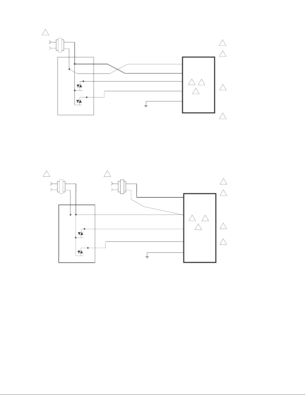
Figure-4 Triac Sink.
Common
Hot (+DC)
Extend
Retract
Green/Yellow
MF51-7203
MF61-7203
2
3
4
1 Provide overload protection and
disconnect as required.
2 Actuators may be wired in
parallel. All actuator black wires
are connected to the
transformer common and all
red wires are connected to the
hot lead. Power consumption
must be observed.
3 The Common connection from
the actuator must be connected
to the Hot connection of the
controller. The actuator Hot
must be connected to the
controller Common.
4 If the controller uses a full-
wave power supply and does
not provide isolated outputs, a
separate transformer is
required.
24 Vac Transformer
1
or 22-30 Vdc
Line
Volts
Hot
Controller
Common
24 Vac Transformer
1
or 22-30 Vdc
Line
Volts
Black
Red
Blue Extend
Yellow/Black
Common
Hot (+DC)
Retract
Green/Yellow
Figure-5 Triac Sink With Separate Transformers.
MF51-7203
MF61-7203
2
3
4
1 Provide overload protection
and disconnect as required.
2 Actuators may be wired in
parallel. All actuator black
wires are connected to the
transformer common and all
red wires are connected to the
hot lead. Power consumption
must be observed.
3 The actuator Hot must be
connected to the controller
Common.
4 If the controller uses a full-
wave power supply and does
not provide isolated outputs, a
separate transformer is
required.
F-27120-5 © Copyright 2008 TAC All Rights Reserved. 7
Page 8
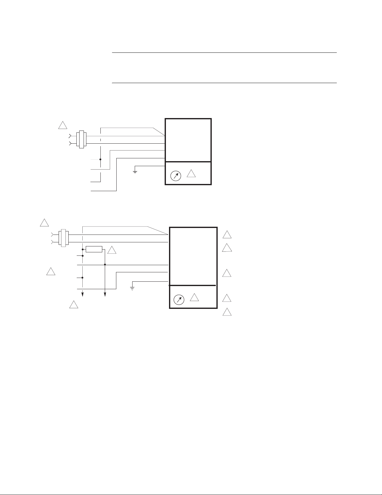
TYPICAL PROPORTIONAL CONTROL (wiring diagrams)
Figure-6 i llustrates typical wiring diag rams for MSx1-7203 Seri es proportional spring return
actuators. See Table-1 for model selection.
Line
Volts
Control Signal
2 to 10 Vdc
Feedback Signal
2 to 10 Vdc
Transformer
1
or 22- 30 Vdc
Line
Volts
Control Signal
4 to 20 mA
4
Feedback Signal
2 to 10 Vdc
Caution:
powered off transformers used to power other devic es utilizing non-isolated full-wave
rectifier power supplies. Refer to
Common Transformer, F-26363
2 to 10 Vdc Proportional Control
24 Vac
Transformer
1
or 22- 30 Vdc
Gra
Blk
Red
Yel/Blk
Blu AO
(-)
(+)
(-)
(+)
4 to 20 mAdc Proportional Control
24 Vac
Com
Com
Yel/Blk
Blu
(-)
(+)
500 Ω
Gra
Blk
3
(-)
(+)
To Additional
2
Actuators
This product contains a half-wave rectifier power supply and must not be
EN-206, Guidelines for Powering Multiple Devi ces from a
for detailed information.
AI
AO
MSX1-7203
L R
MSX1-7203
L R
5
1 Provide overload protection and disconnect
as required.
2 With four actuators wired to one 500 ohm
resistor, a +2% shift of the control signal
may be required. (Actuator input impedance
is 80 k ohm.)
3 A field-supplied 500 ohm resistor (AM-708)
is required between the gray and
yellow/black leads to convert the 4 to 20
mAdc control signal to 2 to 10 Vdc.
5
4 Only connect common to negative (-) leg of
control circuits.
5 To reverse actuator control function
(direct/reverse action), use the reversing
switch, see Figure-9.
Com
Com
Hot (+DC)
AI
Grn/Yel
Hot (+DC)Red
Grn/Yel
Figure-6 Typical Wiring Diagram s for Proportional Control 24 Vac Basic Models.
8 © Copyright 2008 TAC All Rights Reserved. F-27120-5
Page 9
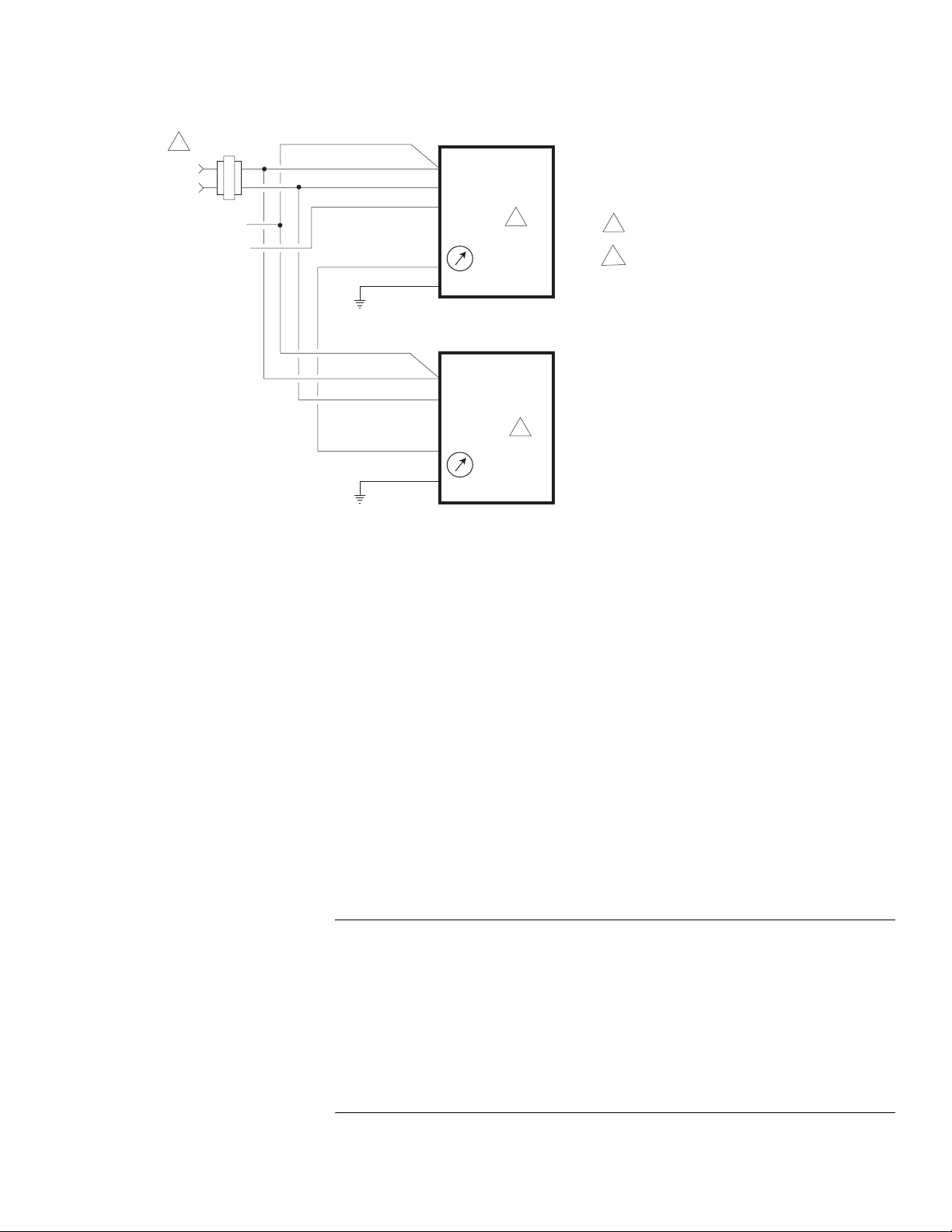
1
Line
Volts
Control Signal
2 to 10 Vdc
Two Actuators Wired in Parallel
24 Vac
Transformer
or 22- 30 Vdc
Gra
Blk
Red
Yel/Blk
Com
Com
Hot (+DC)
AI
(-)
(+)
Blu
AO
Grn/Yel
MSX1-7203
L R
2
1 Provide overload protection and disconnect
as required.
2 To reverse actuator control function
(direct/reverse action), use the reversing
switch, see Figure-9.
Gra
Blk
Red
Yel/Blk
Figure-7 Typical Wiring Diag rams for Proportional Control 24 Vac Models Wired in Parallel.
Com
Com
Hot (+DC)
AI
Grn/Yel
MSX1-7203
2
L R
INSTALLATION
Inspection Inspect the pack age for damage. If damaged, notify the appropriate carrier immediately. If
undamaged, open the package and inspect the device for obvious damage. Return
damaged products.
Requirements • Job wiring diagrams
• Appropriate accessories
• Pliers for removing and inserting connect ing pin
• Installer must be a qualified, experienced technician
• Tool-37, 1-1/2" to 3" adjustable spanner wrench for valve mounting nut
• 5/16" (Tool-20- 1) and 3/4" open-end wrench for stem jam nuts
• 1/8" Allen wrench
• Size 10 IP Torx Plus bit (Mx51 units only)
Precautions General
Warning:
• Electrical shoc k hazar d! Dis conne ct th e power suppl y (l ine p ower) b efore ins tallat ion t o
prevent elect ri c shock and equipment damage.
• Make all con nect ions in acc ord ance wit h the job wi r ing di agram an d i n accor danc e wit h
national and local electrical codes.
• Floating and Proportional Models: These products contain a half-wave rectifier power
supply. They must not be powered with transformers that are used to power other
devices utilizing non-isolated ful l-wave rectifier power suppl ies. Refer to EN-206,
Guidelines For Powering Devices Fr om A Commo n Transformer, F-26363 for detailed
information.
F-27120-5 © Copyright 2008 TAC All Rights Reserved. 9
Use copper conductors only.
Page 10
Caution:
• Avoid electrical noise interference. Do not install near large cont actors, electrical
machinery, or welding equipment.
• Manual overrid e to be used onl y when power is not applied to unit.
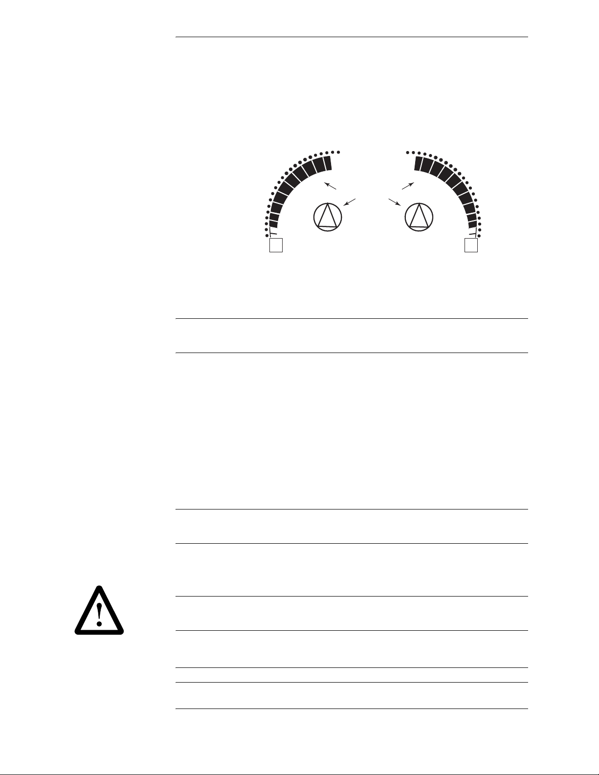
• When operating manual override (observe position indicator, Figure-8), back off 5°
(1/2 turn counter clockwise) from full extended mechanical stop to ensure proper
release.
90
80
70
60
50
40
30
20
10
0
-5
Scale markings indicate
degrees rotation of hub
90
80
70
60
50
40
30
20
10
0
-5
LR
Figure-8 Position Indicator
• Do not drill holes i n a ctuato r body. Six pr e-d rilled holes are locat ed on each si de, under
crosshairs on the label, to accept #10-24 thread-forming screws for mounting
accessories.
Federal Communications Commissio n (FCC)
Note:
This equipment has been tested and found to comply with the limit s for a Class B
digital device, pursuant to Part 15 of the FCC Rules. These lim it s are designed to provide
reasonable prot ection against harmful interference in residenti al installations. Thi s
equipment generates, uses, and can radiate radio frequency energy and may caus e
harmful interference if not installe d and used in accordance with the instructions. Even
when instruct ions are followed, there is no guarantee that interference will not occur in a
particular s etti ng—Which can be determi ned by turn ing the equipment of f and on—th e use r
is encouraged to t ry t o correct the interference by one or more of the following measures:
• Reorient or relocate the receiving antenna.
• Increase the separation between the equipment and receiver.
• Connect the equipment to an outlet on a circuit different fr om that to which the receiv er
is connected.
• Consult the dealer or an experienced radio/television technician for help.
Canadian D epartment of C om m u ni c at ions (D OC )
Note:
This Class B digital apparatus meets all requiremen ts of the Canadian InterferenceCausing Equipment Regulations.
Cet appareil numerique de la classe B respecte toutes les exigences du Reglement sur le
material broil leur du Canada.
European Standard EN 55022
Warning:
environment this product may cause radio interference in which case the user ma y be
required to take adequate measures.
Location
Caution:
explosive vapors are present.
10 © Copyright 2008 TAC All Rights Reserved. F-27120-5
This is a Class B digital (Eur opean Classification) product. In a domestic
Avoid locations where excessive moisture, corrosive fumes, vibra ti on, or
Page 11
Mounting • Mount the linear actuator directly on the valve in locations that clear t he ma ximum
dimensions of th e actuator case (see Figures 19 and 20) .
• Ensure that the valve body is installed correctly. The arrow must point in the direction
of flow. With three -way valves observe stem positi on (stem up) for proper flow
characteri stics. See Table-2.
• The actuator must be mount ed above the centerline of the valve body. This will
minimize the risk of damage to the actuator in the even t of condensation. Refer to
Figure-15, Figure-16, and Figure-17.
Actuator Selection
Mx51 series actuators are used on 1-1/4" to 2" VB-7xxx valves. Mx61 series actuators are
used on 2-1/2" to 4" VB-931x , 2- 1/2" to 5" VB-8xxx, and discontinued 1-1/2” to 4” VB-9xxx
valves (with AM-733 or AM-734kit purchased separat ely).
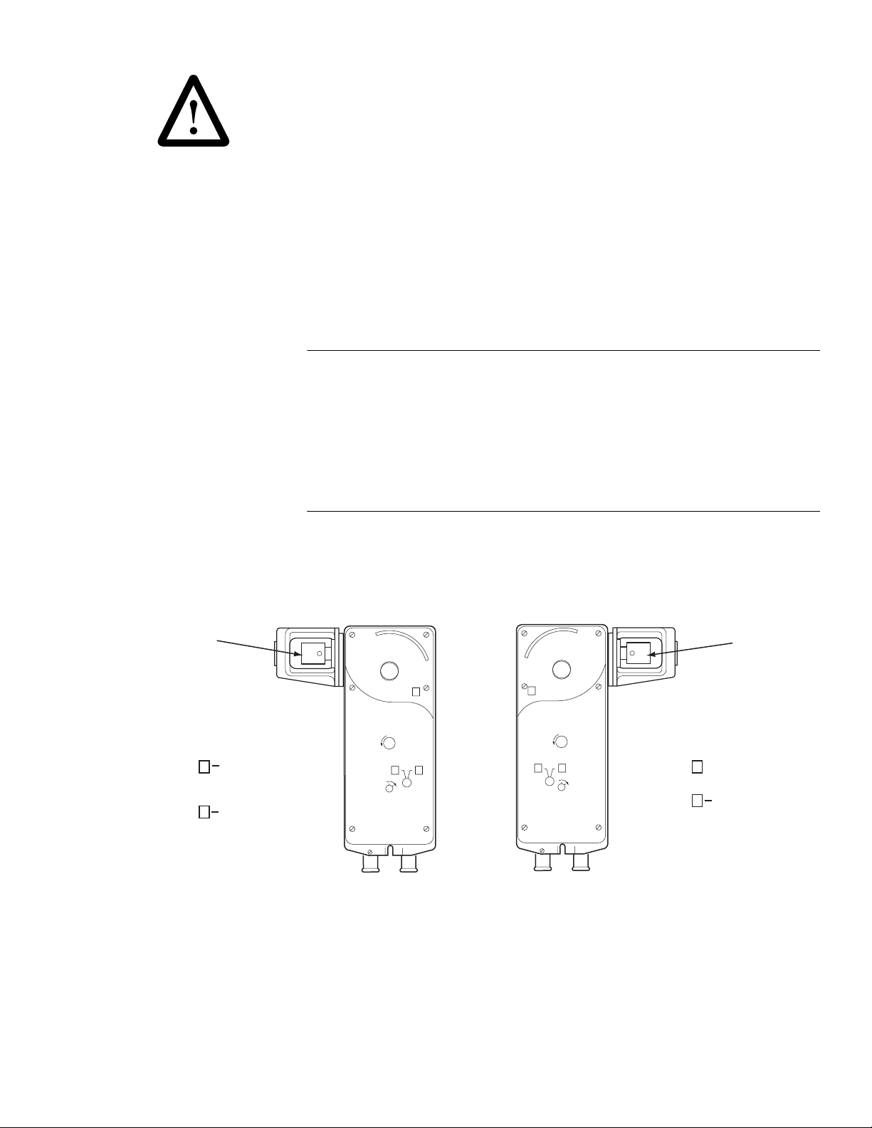
Changing Control Function (proportional units only)
These actuator s are eq uip ped with a switc h to cont rol t he func tion o f the s ign al as r eceived.
See Figure-9.
Rack
Switch on R
Switch on L
Caution:
moves the actuator against the -5° positive stop. Example: Viewing the actuator from the
left side with the sw it ch set to “R” and an increasing signal . The actuator will attempt to
rotate beyond th e -5° st op and wil l stall.
Rack extends on
increasing signal
Rack retracts
on increasing signal
These are spring return actuators. It is possibl e to switch to a direction that
• Install all two-way valves so that t hey close agai nst the f low. An arrow on the valve bo dy
or a tag indicates the proper flow direction.
• Always install three-way mixing valves with two inlets and one outlet.
• Install thr ee-way di ve rting val ves with o ne inl et and t wo out lets . When pi ped for mixing,
Cv’s may differ sli ghtly.
Viewed from "R" side:
R
R
L
LOCK
Viewed from "L" side:
L
R
L
LOCK
Switch on L
Switch on R
Rack
Rack extends
on increasing signal
Rack retracts on
increasing signal
Figure-9 Rotation Switch Settings for MSx1-7203 Proportional Actuators.
F-27120-5 © Copyright 2008 TAC All Rights Reserved. 11
Page 12
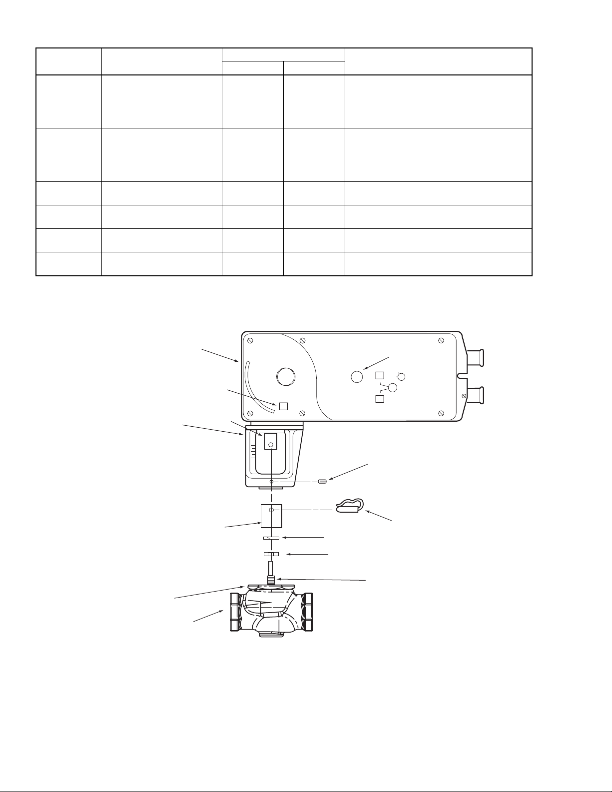
Table-2 Valve Configuration Chart.
Valve Body Valve Body Action
VB-721x
VB-7253
VB-7273
VB-821x
VB-921x
Two-Way Stem Up Open Up Open Port A to AB flow decreases as actuator extends
a
VB-722x
VB-7263
VB-7283
VB-822x
VB-922x
VB-731x
VB-931x
Two-Way Stem Up Close d Up Closed Port A to AB flow increases as actuator extends
a
Three-Way Mixing Up B to AB
VB-732x Three-Way Diverting Up B to AB
VB-8303 Three-Way Piped as Mixing
VB-8303 Three-Way Piped as Diverting
a
Discontinued.
b
Universal diverting/mixing valve, may be piped as either mixing or diverting.
b
b
Normal Position
Valve Stem Flow
Up AB to B
Up B to AB
Action
Port A to A B flow increases as actuator extends
Port B to AB flow decreases as actuator extends
Port B to A flow increases as actuator extends
Port B to AB flow decreases as actuator extends
Port A to B flow increases as actuator extends
Port AB to B flow decreases as actuator exte nd s
Port B to A flow increases as actuator extends
Port B to AB flow decreases as actuator extends
Linear Actuator
Mounting Bracket
Stem Extension
Hex Mounting Nut*
Valve Body*
Label
Rack
Manual Override
L
L
R
Set Screw
Connecting Pin
Lock Washer
Jam Nut
Valve Stem*
* Not included with linear actuator.
Figure-10 Mx51-720x Series Actuato r Exploded View.
12 © Copyright 2008 TAC All Rights Reserved. F-27120-5
Page 13
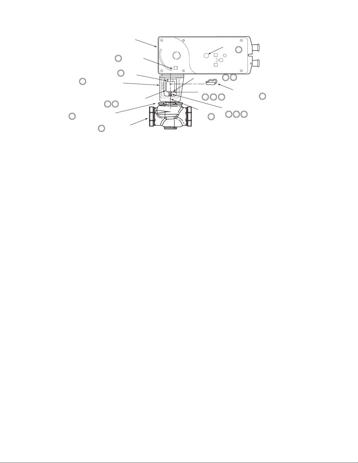
6
Mounting Bracket
Hex Mounting Nut*
6
6
Figure-11 Typical Assembly and Installation of Mx51 Series Actuator to 1-1/4" to 2"
VB-7xxx Series Valve Bodies, Stem-Up Closed or Open, 2-Way and 3-Way Valves.
Linear Actuator
Label
8
(both sides)
7
Rack
Stem Extension
74
Valve Body*
Installation: Mx51-720x Series Actuator to 1-1/4" to 2" VB-7xxx Series Valve
Bodies, Stem-Up Closed or Open, 2-Way and 3-Way
A. Install the act uator onto t he valve. Set up the ass embly accordi ng to the numbered st eps
B. Apply power to the actuat or and check the syste m operation for heati ng or cool ing output
Manual Override
L
L
Lock Washer
Jam Nut
Set Screw
R
2
1
9
5
4
3
Connecting Pin
7
Valve Stem*
3
2
7
6
*Not included with linear actuator.
in Figure-11.
1. Locate the jam nut that came packaged with the actuator.
2. Screw the jam nut onto the valve stem all the way as far as it will go. You may need
to use a 5/16" (Tool-20-1) open-end wrench. At least 1/2" of the val ve stem threads
should extend above the nut.
3. Place lock washer over valve stem.
4. Thread the stem extension onto the val ve stem, making cont act wit h the lock was her
and jam nut.
5. Ensure 15° or 1-1/2 turns of manual override for actuator preload. See Figure-18.
6. Orient the actuator mounting br acket on the valve and tighten the moun ti ng nut
securely again st t he bracket using Tool-37. Raise the valve stem to the full up
position.
7. Rotate stem extension until the through hol e lines up wi th the through hol e of actuat or
rack. Insert con nectin g pin to secure stem extensi on and tighten j am nut agai nst stem
extension using 5/16" (Tool-20-1) open end wrench.
8. Affix open/closed label to the in dicator in the appropriate position.
9. Insert set screw (packaged with a ctuator) into t he m ost accessible side. Tighten with
size 10 IP Torx Plus bit to 20 - 25 lb-in (2.3 to 2.8 N-m).
in response to the control signal.
F-27120-5 © Copyright 2008 TAC All Rights Reserved. 13
Page 14
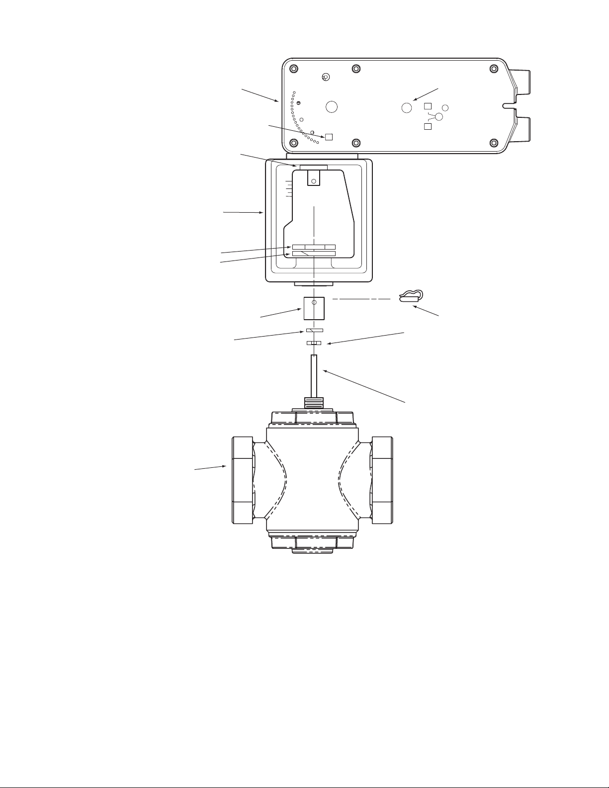
Linear Actuator
Mounting Bracket
Hex Mounting Nut*
Lock Washer
Rack
Label
Manual Override
L
R
L
Lock Washer
Valve Body*
Stem Extension
Figure-12 Mx61-720x Series Actuato r Exploded View.
Connecting Pin
Jam Nut
Valve Stem*
* Not included with linear actuator.
14 © Copyright 2008 TAC All Rights Reserved. F-27120-5
Page 15
Linear Actuator
7
(both sides)
6
Rack
Label
Manual Override
L
R
L
5
5
Mounting Bracket
Mounting Nut*
5
Lock Washer
5
Valve Body*
5
Stem Extension
63
Connecting Pin
Lock Washer
Jam Nut
3
1
2
Valve Stem*
32
2
6
5
*Not included with linear actuator.
6
3
5
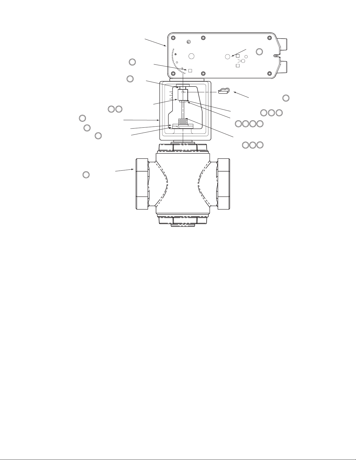
Figure-13 Typical Assembly and Inst allation.
Installation: Mx61-720x Series Actuator to 2-1/2" to 4" VB-9xxx and 2-1/2" to
5" VB-8xxx Series Valve Bodies, Stem-Up Closed 2-Way and 3-Way
A. Install the act uator onto t he valve. Set up the ass embly accordi ng to the numbered st eps
in Figure-13.
1. Locate the jam nut that came packaged with the actuator.
2. Screw the jam nut onto the valve stem all the way as far as it will go (you may need
to use a 3/4" open-end wrench) . At least 1/2" of the val ve stem threads shou ld extend
above the nut. Place the lo ck washer over the valve stem.
3. Thread the stem extension onto the val ve stem, making cont act wit h the lock was her
and jam nut.
4. Ensure 15° or 1-1/2 turns of manual override actuator preload. See Figure-18.
5. Orient the actuator mounting br acket on the valv e, place lock washer over valve stem
and tighten the mounting nut securely against the bracket using spanner wrench.
Raise the valve stem to the f ull up position.
6. Rotate stem extension until the through hol e lines up wi th the through hol e of actuat or
rack. Insert con nectin g pin to secure stem extensi on and tighten j am nut agai nst stem
extension usin g 3/4" open end wrench.
7. Affix open/closed label to the in dicator in the appropriate position.
B. Apply power to the actuat or and check the syste m operation for heati ng or cool ing output
in response to the control signal.
F-27120-5 © Copyright 2008 TAC All Rights Reserved. 15
Page 16
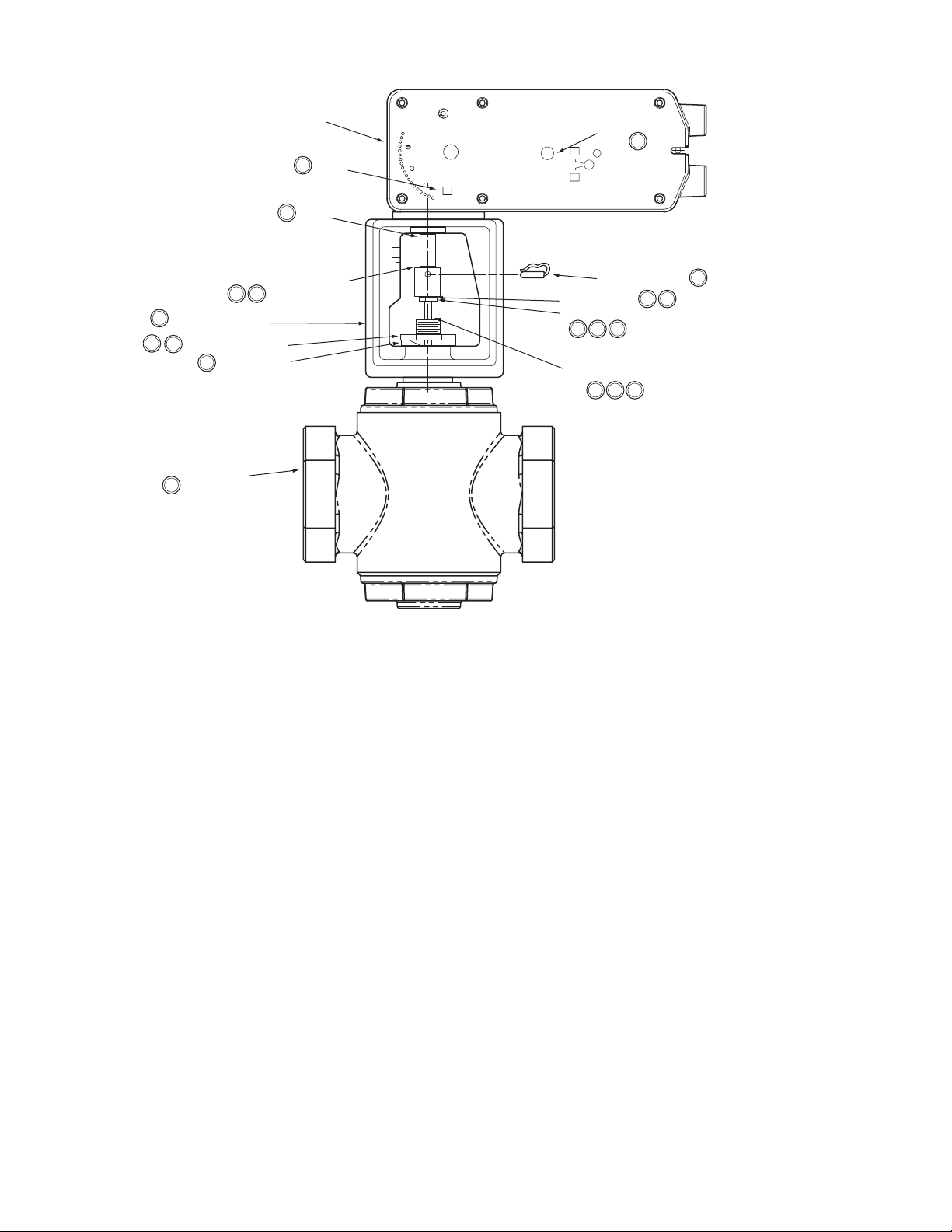
Linear Actuator
7
(both sides)
6
Rack
Label
Manual Override
L
R
L
5
4
Mounting Bracket
Mounting Nut*
2
4
4
Valve Body*
4
Stem Extension
63
Lock Washer
Connecting Pin
Lock Washer
Jam Nut
6
3
1
Valve Stem*
3
2
42
6
3
*Not included with linear actuator.
Figure-14 Typical Assembly and Inst allation.
Installation: Mx61-720x Series Actuator to 2-1/2" to 4" VB-9xxx Series and
2-1/2" to 5" VB-8xxx Valve Bodies, 2-Way Stem-Up Open
A. Install the act uator onto t he valve. Set up the ass embly accordi ng to the numbered st eps
in Figure-14.
1. Locate the jam nut that came packaged with the actuator.
2. Screw the jam nut onto the valve stem all the way as far as it will go (you may need
to use a 3/4" open-end wrench) . At least 1/2" of the val ve stem threads shou ld extend
above the nut. Place the lo ck washer over the valve stem.
3. Thread the stem extension onto the val ve stem, making cont act wit h the lock was her
and jam nut.
4. Orient the actuator mounti ng bracket on the valve. Place lock washe r over valve stem
and tighten the mounting nut securely against the bracket using spanner wrench.
Ensure the valve st em is compl etely pushed down.
5. Insert the hex wrench into manual over ri de and crank to extend the actuator rack to
its fully exte nded posit ion, ba ck off 1- 1/2 turn , and lock (see Figure-1 8). Rem ove hex
wrench to prevent acc idental spring return of the actuator.
6. Rotate stem extension until the through hol e lines up wi th the through hol e of actuat or
rack. Insert connecting pin to secure the asse mbly. Tighten jam nut against st em
extension usin g 3/4" open end wrench.
7. Affix open/closed label to the in dicator in the appropriate position.
B. Apply power to the actuat or and check the syste m operation for heati ng or cool ing output
in response to the control signal.
16 © Copyright 2008 TAC All Rights Reserved. F-27120-5
Page 17
Valve Mounting The valve should be mount ed in a weat her-protected area, in a locat ion that is within the
ambient temperat ure li mits of the act uat or. The instal lat ion of the actuator assembly sho uld
provide clearance on all sides to allow for any maintenance that may be needed (see
Figure-15 and Figure-17). Install the valve ac cording to the instruc ti ons in the appropriate
valve body General Instructions sheet (see Applicable Literature, page 2).
Caution:
Linear actuators are designed to effectively support its own weight. No load or
weight should be resting on the actuator as long term dama ge ma y occur to the actuator,
the mounting connection, or the valve.
• Do not insulate the act uator/linkage. Doing so will result in excess heat buildup wi thi n
the actuator.
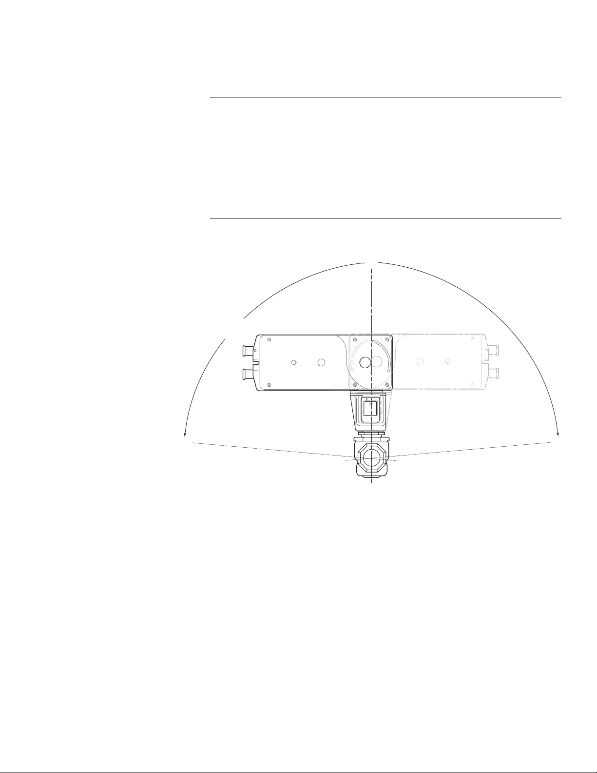
• On non-steam applications the globe valve assem bly must be mounted so that the
actuator is at leas t 5° above the horizontal (Figure-15) to ensure that any condensate
that forms will not travel into the mounting bracket or actuator.
• On steam applications, the globe valve assembly must be mounted at 45° from
vertical. (Fi gure-16).
Mounting Angle Range for
Non-steam Applications
(either side)
0°
85°
85°
Figure-15 Typical Mounting Position.
F-27120-5 © Copyright 2008 TAC All Rights Reserved. 17
Page 18
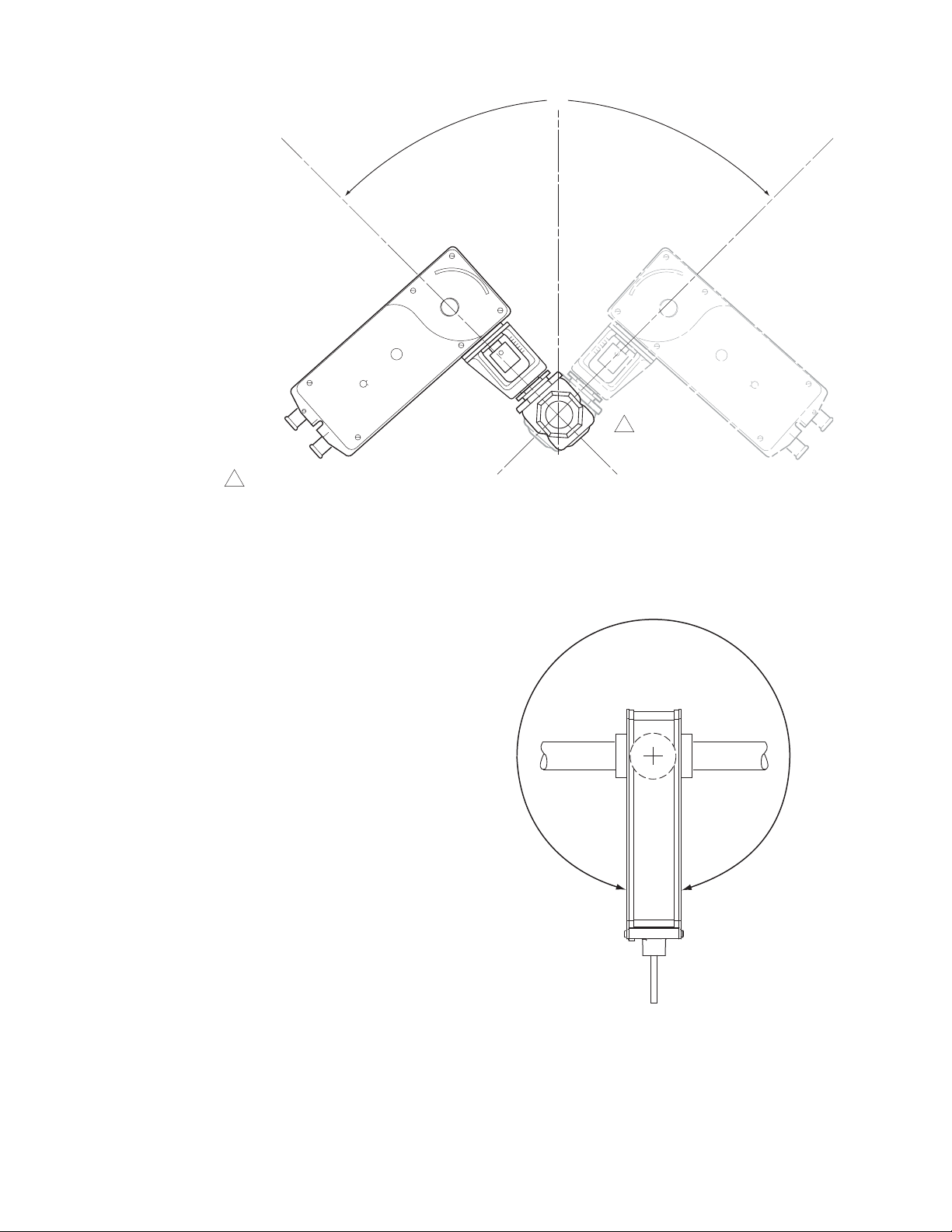
0°
45°
1 For steam applications the valve assembly
must be mounted in piping at a 45° angle
(either side).
Figure-16 Typical Mounting Position for Steam Applications.
45°
1
360° Rotation Range
Figure-17 Actuator Positioned Anywhere Within 360 Degrees.
18 © Copyright 2008 TAC All Rights Reserved. F-27120-5
Page 19
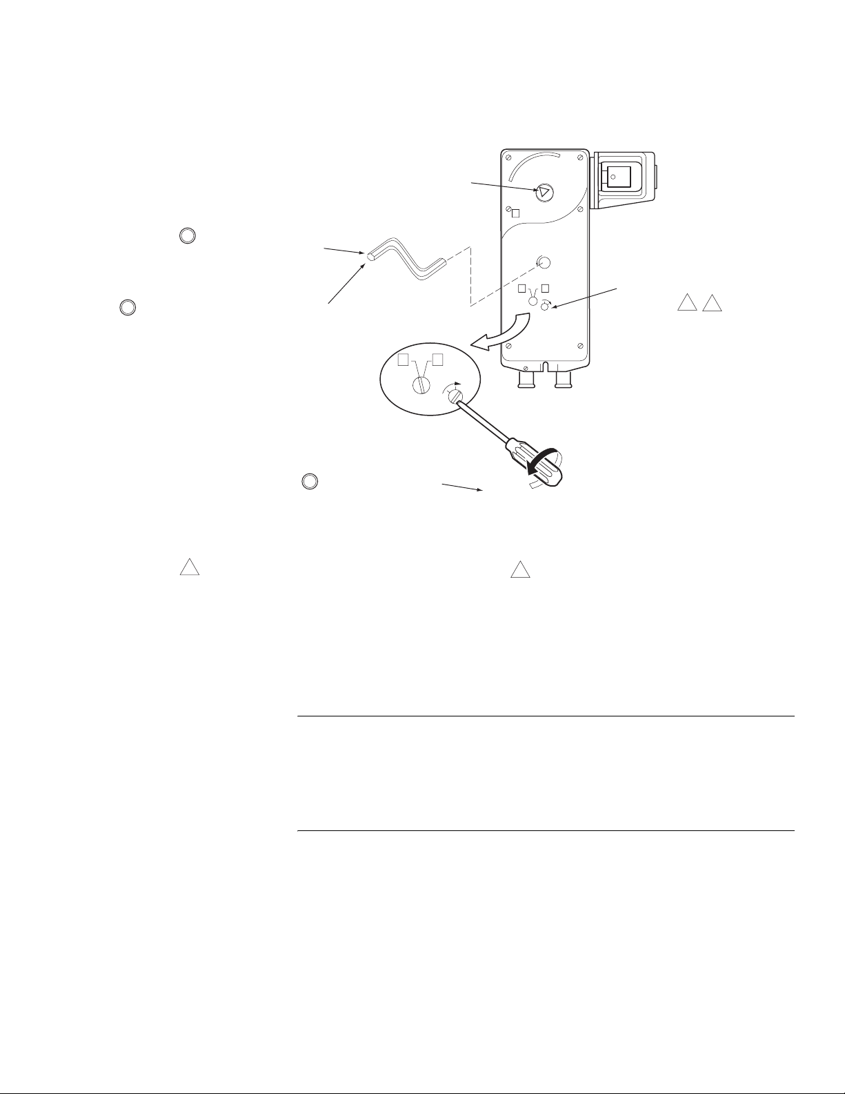
MANUAL OVERRIDE OPERATION
Insert the hex wrench fully
1
into the manual override
mechanism.
Rotation Indicator
Triangle
L
Unlock the manual override, using the
2
hex wrench. To do this, turn, then release
the hex wrench approximately 5° (1/2 turn)
CW, to "jog" the mechanism and release the
manual override preset.
3
1
When necessary, the manual override mechanism may be
used to reposition the actuator at any point between -5°
and 85°. This mechanism is accessible on both sides of
the actuator and can be used to ensure tight close-offs for
valves.
R
L
LOCK
When finished, lock the
manual override by turning
the screwdriver CW (in the
direction of the arrow).
Figure-18 Manual Override.
Unlock
R
L
LOCK
When using the manual override mechanism:
2
Manual Override Locking
Mechanism
1
2
• Fully engage the hex wrench in the manual
override before cranking.
• When operating the manual override, ensure
proper release by backing off 5° from the full
extended mechanical stop.
Caution:
• Only use manual overr ide when the actuator drive motor is not powered.
• Engaging the manual override when th e actuator is powered will cause damage to the
gears.
• Using power tools to adj ust the override will cause damage to t he gears.
• Avoid manually re positioning the actuator beyond its adjustable travel limit setting.
F-27120-5 © Copyright 2008 TAC All Rights Reserved. 19
Page 20

Wiring Requirements Control Leads
See Table-3 for power wiring data. Refer to Figure-1 through Fig ure- 7 for typical wiring.
Table-3 Power Wiring.
Actuator
Voltage
24 Vac
22-30 Vdc
CHECKOUT
After the entire system has been installed and the actuator has been powered up, the
following check can be made for proper system operat ion. Check for cor rect operation of the
valve while actuator is being stroked.
1. Apply power to the actuator. Actuator and valve should be driven to their powered position
as determined by the control signal.
2. Remove power from the actuator. Actuator and valve should return to the spring return
position.
Note:
Check that the transformer(s) are sized properly. (24 Vac)
• If a common transform er i s used with multiple actuators, ma ke sure that polarity is
observed on the secondary. This means connecting all black wires to one leg of the
transformer and all red wires to the other leg of the transformer.
• If multiple t ransformers are us ed with one control signal, make sure all black wires are
tied togethe r and tied to control signal negat ive (-).
• If the controll er uses a full-w ave power sup ply and does not pr ovide i solat ed output s, a
separate transformer is required.
Part Number
MAx1-7203 —
MFx1-7203
MSx1-7203
12 AWG14 AWG16 AWG18 AWG20 AWG22 AWG
500
(152)
600
(183)
Maximum Wire Run in ft. (m)
330
(101)
300
(91)
380
(116)
200
(61)
200
(61)
240
(73)
130
(40)
130
(40)
150
(46)
——
80
(24)
90
(27)
50
(15)
60
(18)
THEORY OF OPERATION
MAINTENANCE
The MA, MF and MS series actuat ors are directl y mounted ont o the valv e without the use of
separate linkage. They are equipped with true mechanical spring return operation for
reliable, posi tive actuator operation in the unpowered condition.
Linear series actuators use a brushless DC motor which is controlled by a microprocessor.
The microprocessor supplies the intelligence to provide a constant motion rate and to know
the actuator ’s exact normal position and to match actuator mechanica l st roke to the control
input signal range on proportional (MS) models. The microprocessor monitors and controls
the brushl ess DC motor’s r otation and provides a digi tal rotation sensing functi on to prevent
damage to the actuator in a stall condition. The actuator may be stalled anywhere in its
normal rotation without the need of mechanical sw it ches.
When power is applied to two-position (MA) models, the actuator moves to its full stroke
position, at the same time tensing the spring return mechanism. When power is removed,
the spring returns the actuator to its norma l position.
When power is applied to floating (MF) and proportional (MS) models, the actuator first
moves to its zero position, then moves to the position dictated by the control input signal.
For proportional (MS) models, when the actuator encounters a stall condition (end of valve
stroke), it recalibrates itself if necessary so that its mechanical stroke matches the control
signal input span. The feedback signal range is also matched to the mechanical stroke. If
power is lost, the actuator spring returns to its normal position.
Regular maintenance of the total system is recommended to assure sustained optimum
performance. The Linear series actuators are maintenance free.
20 © Copyright 2008 TAC All Rights Reserved. F-27120-5
Page 21
FIELD REPAIR
DIMENSIONAL DATA
Actuator: None. For repla cement contact your TAC Represent ative and specif y the desired
model number from Table 1.
Linkage parts: All are supplied with the actuator. Stem extension, jam nut, washer, and
connecting pin may be purchased separately if lost. See ACCESSORIES, page 4.
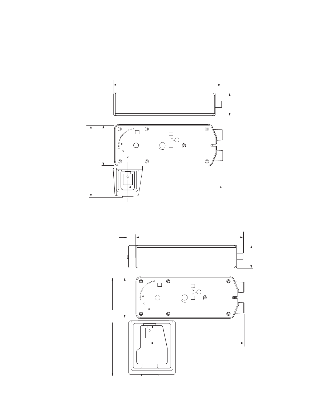
10-9/16 (268)
2-33/64
(64)
7
(178)
4
(103)
R
L
LOCK
R
9-1/4 (235)
Minimum clearance: 5" for actuator removal.
Figure-19 Mx51-720x Spring Retur n Valve Actuator Dimensions.
9/16
(14)
R
4
(103)
10-9/16 (268)
L
R
LOCK
Dimensions shown
are in inches (mm).
2-33/64
(64)
9-1/2
(241)
Dimensions shown
are in inches (mm).
9-1/4 (235)
Minimum clearance: 5" for actuator removal.
Figure-20 Mx61-720x Spring Return Valve Actuator Dimensions.
F-27120-5 © Copyright 2008 TAC All Rights Reserved. 21
Page 22

22 © Copyright 2008 TAC All Rights Reserved. F-27120-5
Page 23

F-27120-5 © Copyright 2008 TAC All Rights Reserved. 23
Page 24

Copyright 2008, TAC
All brand names, trademarks and registered
trademarks are the property of their respective
owners. Information contained within this
document is subject to change without notice.
F-27120-5
TAC
1354 Clifford Avenue
P.O. Box 2940
Loves Park, IL 61132-2940
www.tac.com
 Loading...