

Page 1
TAC
1354 Clifford Avenue
P. O. Box 2940
Loves Park, IL 61132-2940
www.tac.com
Application
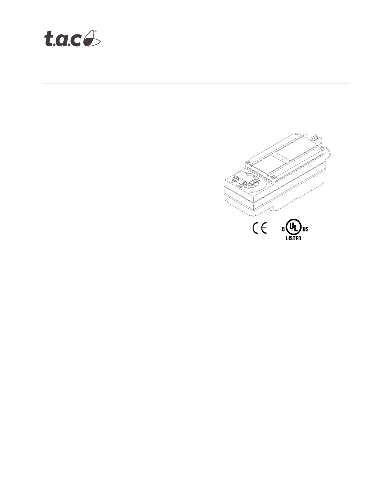
TAC DuraDrive Direct Coupled Actuators are designed
to be used in both damper and valve control
applications. The follow general instructions are for
damper applications, refer to the Applicable Literature
table for valve literature.
The MA40-717X series actuators are over the shaft
spring return actuators used for two-position control
applications.
Features
MA40-717X Series
TAC DuraDrive™ Series Spring Return
Two Position Actuators
General Instructions
• 150 lb-in (17 N-m) rated torque
• NEMA Type 4 housing (IEC IP56)
• Custom automatic current sensing motor control
provides extended reliability and repeatable timing
• Direct coupled to the damper shaft with dual
industrial hardened universal mounting clamps
• Two-position actuator controlled by SPST controller
• Clockwise or counterclockwise spring return is
determined by actuator mounting position
• Accurate 93° travel digitally controlled
• Integral position indication scale
• Rugged die-cast housing
• Oil immersed gear train provides continuous
lubrication
• Rated for operating temperature up to 140 °F
• Five year warranty
†
† Refer to Table-1 to identify specific models that are
in conformance with CE standards.
Printed in U.S.A. 8-06 © Copyright 2006 TAC All Rights Reserved. F-26742-2
Page 2

Applicable Literature
F-Number Description Audience Purpose
F-26750
F-26751
F-26646
F-26752
F-26080 EN-205 Water System Guidelines
F-13755 CA-28 Control Valve Sizing
F-11080 Valve Selection Chart Water
F-11366 Valve Selection Chart Steam (two-way valves only)
MX40-6XXX-2XX, MX40-7XXX-2XX Series
Actuator/Linkage Assemblies General Instructions
VX-2000 Series Ball Valve Assembly Installations
Instructions
MX40-7XXX, MX40-6XXX Series TAC DuraDrive
Actuator Selection Guide
VX-2000, VX-7000 Series
MX40-7XXX, MX40-6XXX Series
Ball/Linked Globe Valve Assemblies
Actuator/Linkage Assemblies Selection Guide
– Sales Personnel
– Application Engineers
–Installers
– Service Personnel
– Start-up Technicians
– Sales Personnel
– Application Engineers
–Installers
– Service Personnel
– Start-up Technicians
– Sales Personnel
– Application Engineers
–Installers
– Service Personnel
– Start-up Technicians
– Sales Personnel
– Application Engineers
–Installers
– Service Personnel
– Start-up Technicians
– Application Engineers
–Installers
– Service Personnel
– Start-up Technicians
– Application Engineers
–Installers
– Service Personnel
– Start-up Technicians
Describes the globe valve actuator/linkage
assembly’s features, specifications, and
possible applications. Provides step-bystep mounting instructions.
Describes the actuator/linkage/ball valve
assembly’s features, specifications, and
possible applications. Provides step-bystep mounting instructions.
Provides actuator specifications and part
number cross referencing of phased out
actuators with the new TAC direct-coupled
actuators.
Provides part number cross referencing of
phased out actuators with the new TAC
direct-coupled actuators.
Describes TAC approved water treatment
practices.
Provides charts, equations, and diagrams
to assist in the configuration of valve
system applications. TOOL-150, valve
sizing slide rule may be purchased
separately.
2 © Copyright 2006 TAC All Rights Reserved. F-26742-2
Page 3

SPECIFICATIONS
Inputs
Control Signal: Two wire, SPST or Triacs. See Figure-1 through Figure-1.
Power Input: See Table-1. All 24 Vac circuits are Class 2. All circuits 30 Vac and above are
Class 1.
Connections:
Power, 24 inch (61 cm) long, 18 AWG color coded pigtail leads.
Control, 24 inch (61 cm) long, 22 AWG color coded pigtail leads.
Outputs
Electrical:
Stroke, Electronically limited to 93° ±1°.
Torque See Table-1.
Duty Cycle 100%.
Timing See Table-1.
Mechanical:
Anti-Rotation Bracket,
Standard 9" long x 13/16" wide (229 x 21 mm), included with the actuator.
Optional Order AM-752 (4" long x 1-11/16" wide) for mounting the actuator in narrow
spaces.
Universal Mounting Clamps, Two clamps are required for all mounting configurations.
Standard 3/8" to 1/2" (10 to 13 mm) round and square shaft mounting clamps are
included with the actuator.
Optional Order AM-753 for 5/8" (16 mm) square and 3/4" to 1" (19 to 25 mm) round
damper shafts, two per package.
Minimum Damper Shaft Length,
Standard Damper shaft must be at least 4-5/8" (117 mm) long for standard mounting.
Optional Shorter than standard length shafts require the AM-676 shaft extension
(order separately).
Position Indicator, Scale numbered from 0 to 95°, provided for position indication.
Nominal Damper Area, Actuator sizing should be done in accordance with damper
manufacturer’s specifications.
Direction of Rotation, Clockwise or counterclockwise rotation determined by actuator
mounting. The zero (0) position on the position indicator is the normal or spring return
position.
Environment
Ambient Temperature Limits:
Shipping & Storage, -40 to 160°F (-40 to 71°C).
Operating, -25 to 140°F (-32 to 60°C).
Humidity: 15 to 95% RH, non-condensing.
Location: NEMA 1. NEMA Type 4 (IEC IP56) with customer supplied water tight conduit
connectors.
Agency Listings
UL 873: Underwriters Laboratories Inc. listed (File # E9429 Category Temperature-
Indicating and Regulating Equipment).
CUL: UL Listed for use in Canada by Underwriters Laboratories. Canadian Standards
C22.2 No. 24-93.
European Community: EMC Directive (89/336/EEC). Low Voltage Directive (72/23/EEC).
Machinery Directive (89/392/EEC). Safety Directive (92/59/EEC). See Table-1 for specific
models.
F-26742-2 © Copyright 2006 TAC All Rights Reserved. 3
Page 4
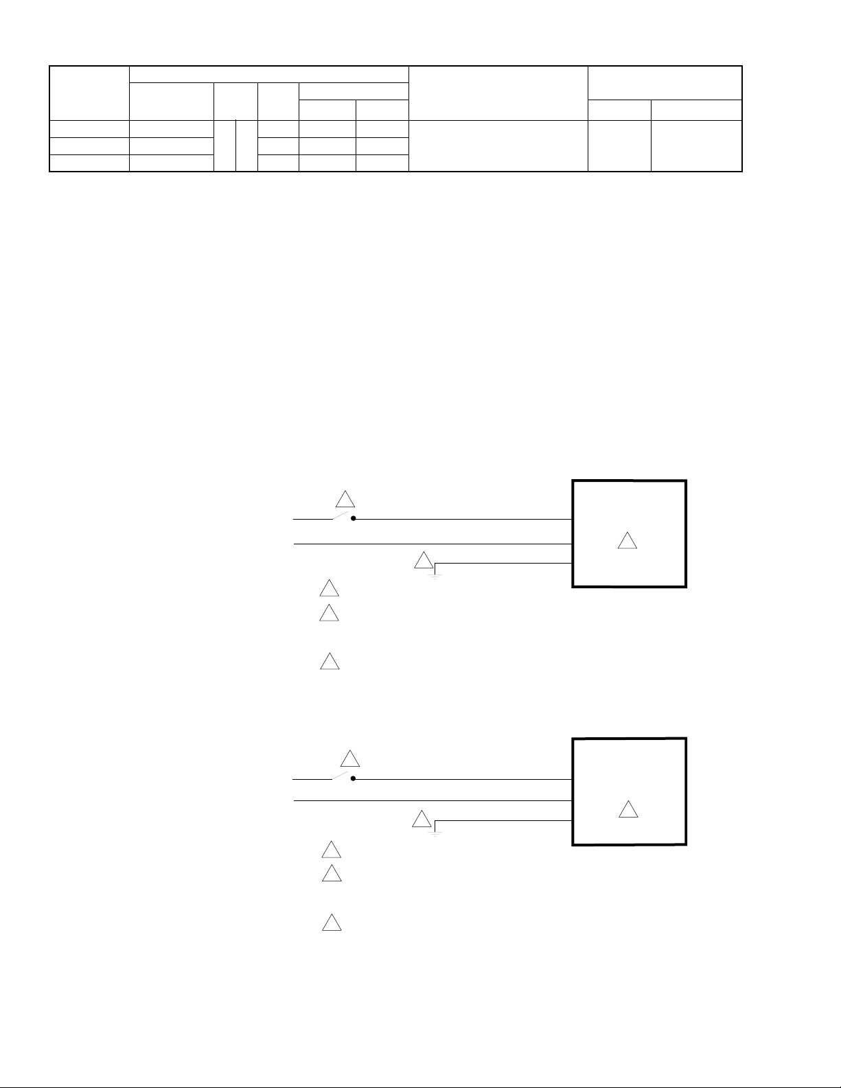
Table-1 Model Chart.
Part
Number
MA40-7173
MA40-7171
a
This model is in conformance with CE standards.
Voltage Hz Watts
a
24 Vac ±20%
a
240 Vac ±10% 7.4 11.8 9.5
Actuator Power Input Approximate 93° Rotation
50 60
VA
Running Holding Minimum Maximum Stall
5.4 9.6 4.1
ACCESSORIES
AM-674 Weather Shield - steel
AM-676 Universal Shaft Extension, approximately 9-1/2" (242 mm) long for use on 3/8" to
11/16"(10 to 17 mm) Round Shafts, 3/8" to 9/16" (10 to 14 mm) square shafts
(AM-753 clamps required)
AM-751 Standard Anti-rotation Bracket 9" long x 13/16" (229 x 21 mm) wide (229 x 21 mm),
included with actuator
AM-752 Optional Anti-rotation Bracket 4" long x 1-11/6" wide (102 x 43 mm), for narrow
spaces
AM-753 Optional Universal Mounting Clamps for 5/8"(16 mm) square shaft, 3/4" and 1"
(19 to 25 mm) round shafts (two per package)
AM-754 Standard Universal Mounting Clamps for 3/8" to 1/2" (10 to 13 mm) round and
square shafts, two included with actuator
AM-756 Metric Conduit Adaptor M20 x 1.5 to 1/2" NPT (two per package)
TF-711-02 1/2" Sealtight Water Tight Conduit Connector (straight)
TF-713-02 1/2" Sealtight Water Tight Conduit Connector (90°)
X-5521 1/2" Pipe Plug, included with actuator
Timing in Seconds
@ 70° F (21° C)
for Rated Torque
145 150 (17) 450 (51)MA40-7170 120 Vac ±10% 7.2 11.4 9.4
Output Torque Rating
lb.-in. (N-m)
TYPICAL APPLICATIONS (wiring diagrams)
1
120 Vac
1 SPST or Triac Controller.
2 Unused conduit port must remain plugged with a water tight pipe
plug as shipped from factory to maintain NEMA Type 4 or IP56
rating.
3 Ground wire may be Green on some models.
Figure-1 Typical MA40-7170 Wiring Diagram.
1
240 Vac
1 SPST or Triac Controller.
3
3
Black
White
Brown
Light Blue
L1
MA40-7170
L2
2
GRDGreen/Yellow
MA40-7171
L1
L2
GRDGreen/Yellow
2
2 Unused conduit port must remain plugged with a water tight pipe
plug as shipped from factory to maintain NEMA Type 4 or IP56
rating.
3 Ground wire may be Green on some models.
Figure-2 Typical MA40-7171 Wiring Diagram.
4 © Copyright 2006 TAC All Rights Reserved. F-26742-2
Page 5
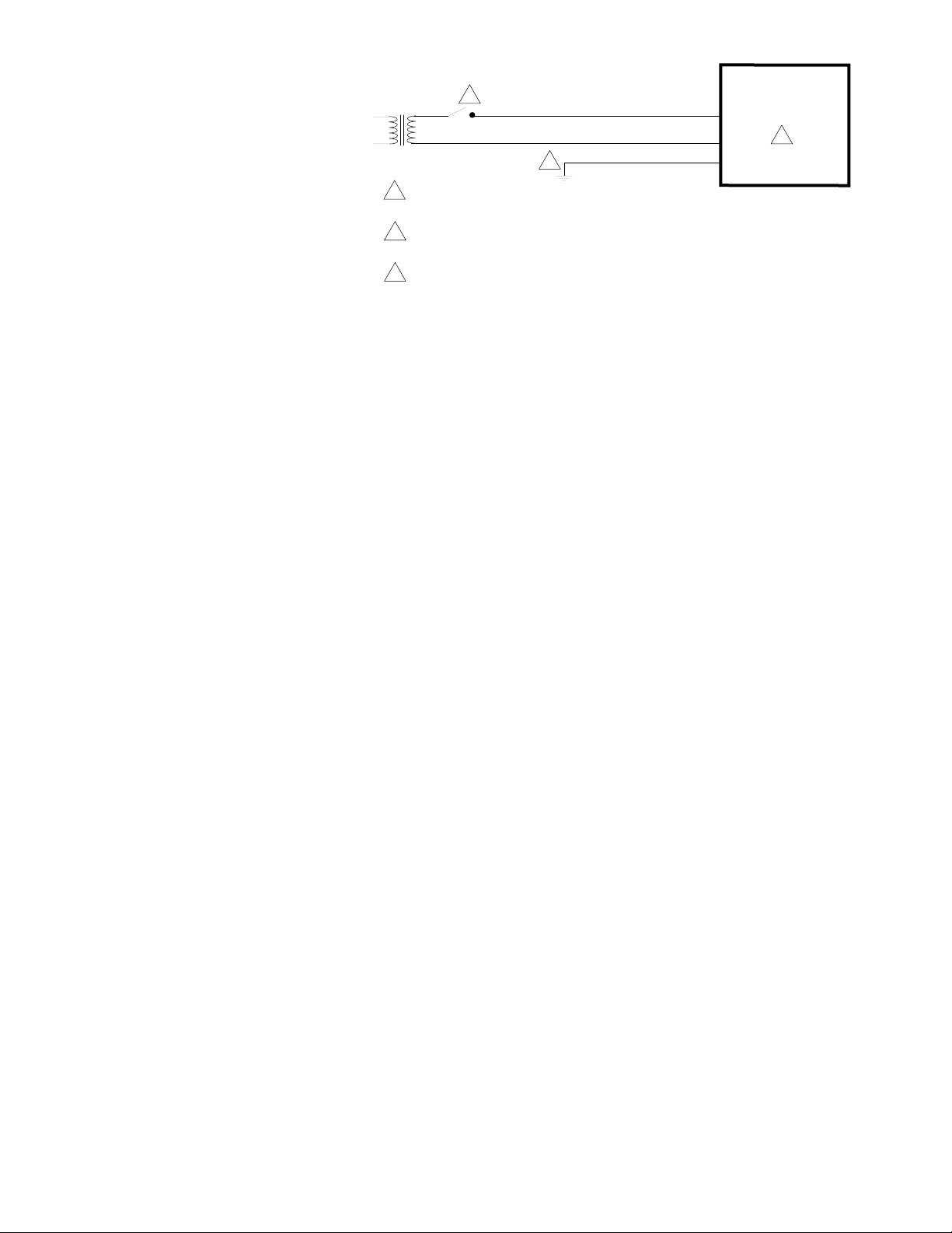
1
24 Vac
3
1 SPST or Triac Controller. Multiple MA40-7173 actuators may be powered
by a single 24 Vac transofrmer.
2 Unused conduit port must remain plugged with a water tight pipe plug as
shipped from factory to maintain NEMA Type 4 or IP56 rating.
3 Ground wire may be Green on some models.
Figure-3 Typical MA40-7173 Wiring Diagram.
Black
Black/Blue
24H
24G
GRDGreen/Yellow
MA40-7173
2
INSTALLATION
Inspection Inspect the package for damage. If damaged, notify the appropriate carrier immediately.
If undamaged, open the package and inspect the device for obvious damage. Return
damaged products.
Requirements • Job wiring diagrams
• Tools (not provided)
– Socket wrench 1/2 inch, used for universal mounting clamp nuts
– Open-end wrench 10 mm, used for installing AM-676 universal shaft extension
– Slotted screwdriver, used for installing anti-rotation brackets
– Allen wrench 3/16", used for manual override
• Appropriate accessories
– Water tight 1/2 inch conduit seals TAC part number TF-711-02 or T&B #5332
(straight, TAC part number TF-713-02 or T&B #5352 (90°), or equivalent.
– Water tight 1/2 inch flexible conduit (e.,g. Anaconda: Sealtight) or 20 mm flexible
water tight conduit when using AM-756 metric conduit adapter with appropriate
metric water tight seals.
– Water tight 1/2 inch flexible conduit (Anaconda: Sealtight) or 20 mm flexible water
tight conduit when using AM-756 metric conduit adapter
– Two #8 1/2 inch (13 mm) sheet metal screws for mounting anti-rotation bracket
(optional)
• Training: Installer must be a qualified, experienced technician
F-26742-2 © Copyright 2006 TAC All Rights Reserved. 5
Page 6

Precautions General
Warning:
• Electrical shock hazard! Disconnect the power supply (line power) before and during
installation to prevent electric shock and equipment damage.
• Make all connections in accordance with the wiring diagram and in accordance with
national and local electrical codes.
Caution:
• Avoid electrical noise interference. Do not install near large contactors, electrical
machinery, or welding equipment.
• Avoid locations where excessive moisture, corrosive fumes, vibration, or explosive
vapors are present.
Federal Communications Commission (FCC)
Note:
This equipment has been tested and found to comply with the limits for a Class B
digital device, pursuant to Part 15 of the FCC Rules. These limits are designed to provide
reasonable protection against harmful interference in residential installations. This
equipment generates, uses, and can radiate radio frequency energy and may cause
harmful interference if not installed and used in accordance with the instructions. Even
when instructions are followed, there is no guarantee that interference will not occur in a
particular installation. If this equipment causes harmful interference to radio or television
reception— which can be determined by turning the equipment off and on—the user is
encouraged to try to correct the interference by one or more of the following measures:
• Reorient or relocate the receiving antenna.
• Increase the separation between the equipment and receiver.
• Connect the equipment to an outlet on a circuit different from that to which the receiver
is connected.
• Consult the dealer or an experienced radio/television technician for help.
Use copper conductors only.
Location
Canadian Department of Communications (DOC)
Note:
This class B digital apparatus meets all requirements of the Canadian InterferenceCausing Equipment Regulations.
Cet appareil numerique de la classe B respecte toutes les exigences du Reglement sur le
material broilleur du Canada.
European Standard EN 55022
Warning:
this product may cause radio interference in which case the user may be required to take
adequate measures.
Caution:
This is a class B (European Classification) product. In a domestic environment
• To maintain NEMA Type 4 rating, use water tight 1/2" flexible conduit only, with 1/2"
conduit connector of the water tight type, TAC part number TF-711-02 or T&B #5332
(straight), TAC part number TF-713-02 or T&B #5352 (90°), or equivalent.
• For metric conduit applications using AM-756 conduit adapters, use the appropriate
metric water tight seals to maintain compliance with IP56 or NEMA Type 4 rating.
• Use a water tight 1/2" pipe plug in any unused actuator conduit ports and seal with
water tight tape to stay in compliance with NEMA Type 4 or IP56 rating. Use TAC part
number X-5521, Grinnell #8700159257 (black), Grinnell #8700159851 (galvanized), or
equivalent. Actuators with unused conduit ports are shipped with the unused port
plugged.
6 © Copyright 2006 TAC All Rights Reserved. F-26742-2
Page 7
Mounting Mount the TAC DuraDrive Actuator directly on the damper shaft in locations that clear the
maximum dimensions of the actuator case and allow the actuator to be mounted flush to the
surface of the terminal box and perpendicular to the damper shaft.
Note:
Some terminal boxes have sheet metal screw heads or other protrusions near the
damper shaft. In these cases, a spacer or shim may be added under the mounting tab of
the actuator to make the actuator perpendicular to the shaft.
Damper Actuator Sizing
Correct sizing of the actuator is necessary for proper control of dampers. The area of
damper that can be controlled by a given actuator is dependent upon the type of damper,
the quality of the damper, the pressure drop across the damper in the closed position, and
the velocity of the air flow through the damper. To obtain actual damper torque
requirements, contact the damper manufacturer.
Damper Shaft Sizing
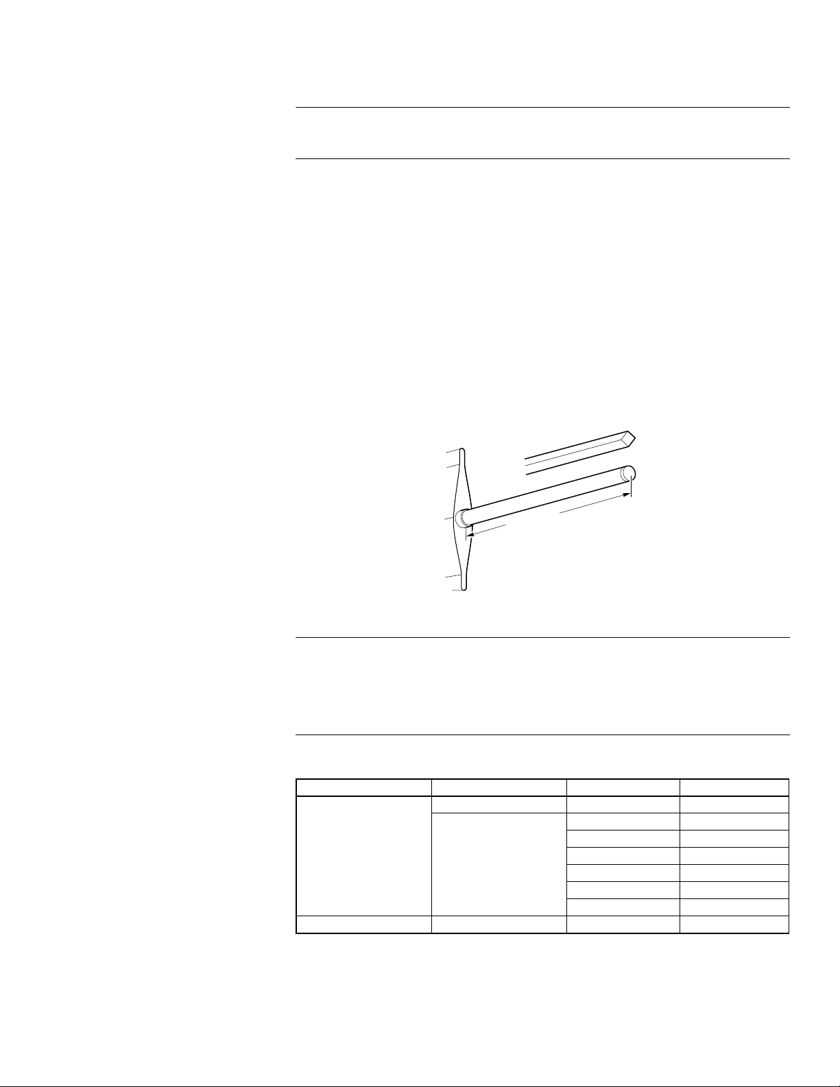
Use the “Long Damper Shaft” mounting instructions if the damper shaft is at least 4-5/8"
(117 mm) long.
Use the “Short Damper Shaft” mounting instructions if the damper shaft is shorter than
4-5/8" or the area around the damper shaft is too narrow to allow standard mounting, as
described in the “Long Damper Shaft” mounting section. See Figure-4 for minimum shaft
length.
Min. 4-5/8" (117 mm)
Figure-4 Long Damper Shaft Dimensions.
Caution:
The MA40-717X actuator is not designed to be used on aluminum damper
shafts, solid steel shafts smaller than 1/2" diameter round or 1/2" square, or hollow steel
shafts smaller than 3/4" round. The actuator can produce up to 450 in-lbs (51 N-m)
maximum stall torque, which could result in the actuator snapping off an aluminum damper
shaft or an improperly sized steel damper shaft. Refer to Table-2 for nominal damper shaft
sizes.
Table-2 Steel Damper Shaft Specifications.
Damper Shaft Shape Damper Shaft Type O.D. (Nominal)
Solid bar 1/2" to 1" 0
3/4" 0.375
13/16" 0.683
Round
Square Solid bar 1/2" to 5/8" 0
a
Damper shaft sizes over 1/2" (13 mm) O.D. require AM-753 universal mounting clamps.
Hollow tubing
27/32" 0.626
7/8" 0.805
15/16" 0.808
a
I.D. (Maximum)
1" 0.930
F-26742-2 © Copyright 2006 TAC All Rights Reserved. 7
Page 8

Mounting the Actuator for Clockwise or Counterclockwise Spring Return
The zero (0) position on the position indicator is the normal or spring return position. When
the actuator is mounted with the “R” side facing the installer and the control signal increases
the actuator will rotate in the counterclockwise direction. When the actuator is mounted with
the “L” side facing the installer and the control signal increases the actuator will rotate in the
clockwise direction.
Long Damper Shaft
1. Move the damper to its normal position. Verify the controller action is set to match the
damper application. See TYPICAL APPLICATIONS (wiring diagrams).
– For normally closed damper, when damper is closed the actuator position indicator
should be at 0°. When damper is open the actuator position indicator should be at
90°.
– For normally opened damper, when damper is open the actuator position indicator
should be at 0°. When damper is closed the actuator position indicator should be at
90°.
Note:
The actuator comes equipped with two AM-754 universal mounting clamps. For
damper shafts larger than 1/2" (13 mm) in diameter, the AM-753 universal mounting
clamps are required (order separately). The AM-753 clamps accommodate round shaft
sizes ranging from 3/4" to 1" (19 to 25 mm) or 5/8" (16 mm) square shafts.
2. Slide the actuator over the shaft and into its desired final mounting position.
– If the damper shaft rotates clockwise to the closed position, mount the actuator with
the side marked “R” facing the installer. See Figure-5.
– If the damper shaft rotates counterclockwise to the closed position, mount the
actuator with the side marked “L” facing the installer. See Figure-6.
3. Hand tighten the nuts on both of the actuator’s universal mounting clamps.
4. Align the actuator at 90° (perpendicular) to the damper shaft. See Figure-7.
5. Slide the anti-rotation bracket pin into the mounting slot on the actuator and drill
mounting holes. See Figure-7. For narrow spaces, the AM-752 anti-rotation bracket is
recommended (order separately).
6. Attach one side of the anti-rotation bracket to the mounting surface with one of the
screws provided. Leave the screw loose so that the bracket can be rotated. See
Figure-5 for clockwise or Figure-6 for counterclockwise spring return.
7. Pivot the anti-rotation bracket away from the actuator. See Figure-5 or Figure-6.
8. Loosen the universal mounting clamps, making sure not to move the damper shaft.
Rotate the actuator approximately 5° in the direction which would open the damper. See
Figure-5 or Figure-6.
9. Tighten all of the universal mounting clamp nuts with a 1/2" socket wrench. Apply
4 to 6 ft-lbs. (5 to 8 N-m) of torque.
10. Manually rotate the actuator toward the full-closed position to apply pressure to the
damper seals. See Figure-5 or Figure-6.
11. Pivot the anti-rotation bracket into place and secure the other side of the bracket onto
the mounting surface with the other screw provided with the actuator. See Figure-5 or
Figure-6.
12. Verify that the damper is in its full-closed position and actuator at 90° (perpendicular) to
the damper shaft. See Figure-5 or Figure-6.
8 © Copyright 2006 TAC All Rights Reserved. F-26742-2
Page 9
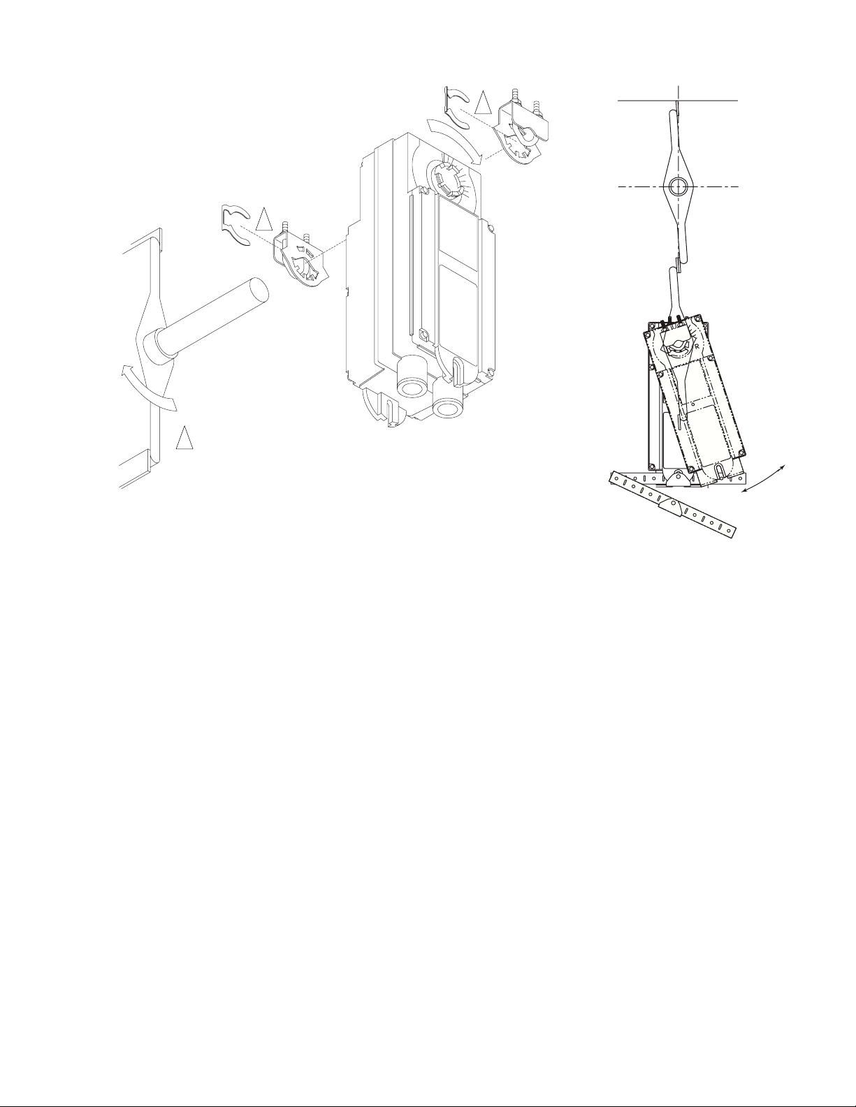
1
1 Two AM-754 Universal Mounting Clamp Assemblies
are provided with each actuator. Each clamp
assembly includes 1 universal mounting clamp and
1 retaining clip. Two Universal Mounting Clamp
Assemblies are required for all mounting
configurations.
CENTERLINE
1
R
5
Figure-5 Long Damper Shaft Mounting with Clockwise Spring Return for Normally Closed Damper.
F-26742-2 © Copyright 2006 TAC All Rights Reserved. 9
Page 10
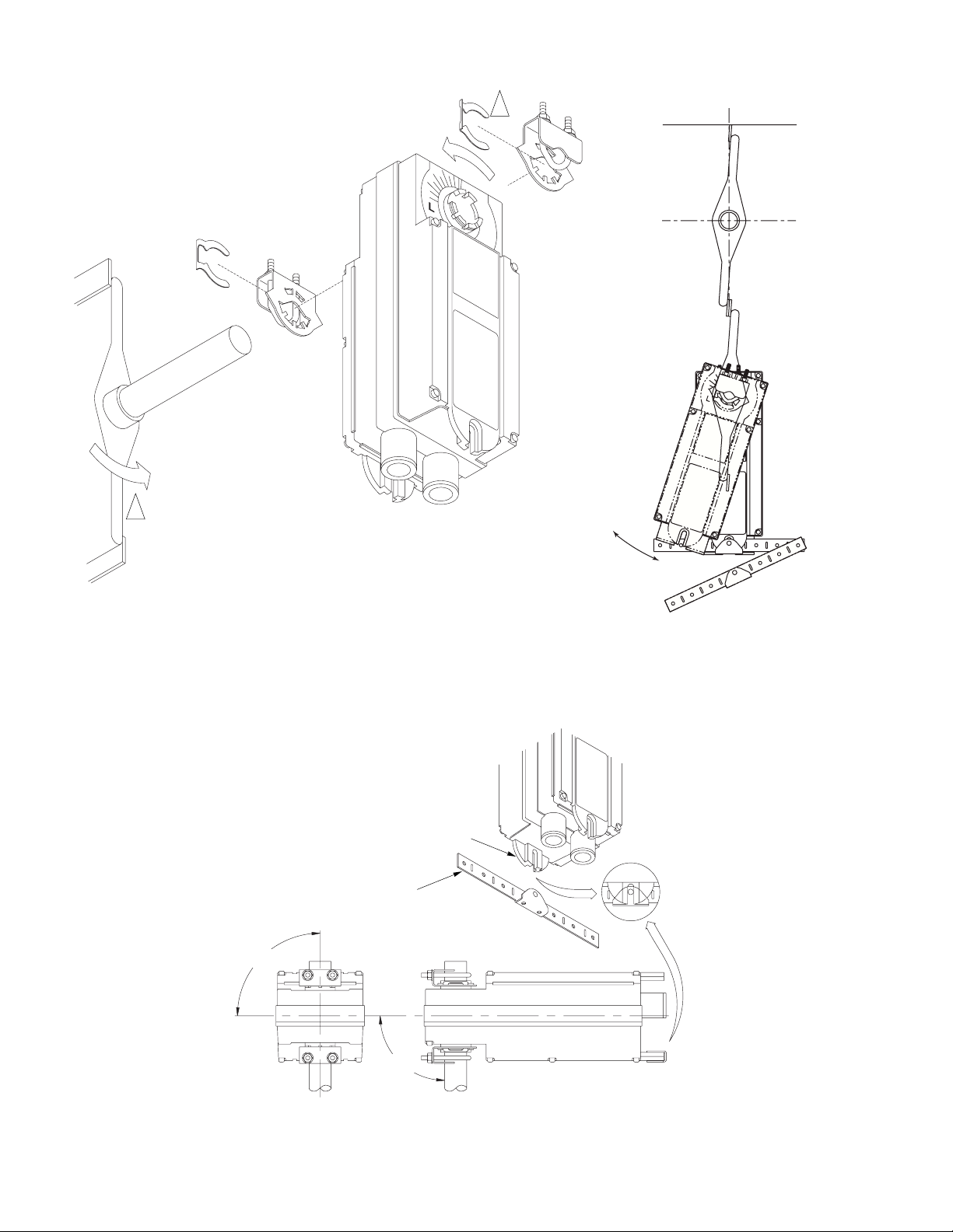
1 Two AM-754 Universal Mounting Clamp Assemblies
are provided with each actuator. Each clamp
assembly includes 1 universal mounting clamp and
1 retaining clip. Two Universal Mounting Clamp
Assemblies are required for all mounting
configurations.
1
5
CENTERLINE
Figure-6 Long Damper Shaft Mounting with Counterclockwise Spring Return for Normally Closed Damper.
Actuator Mounting Slot
AM-751
Anti-rotation Bracket
90
90
Figure-7 Mounting Anti-rotation Bracket to Actuator.
10 © Copyright 2006 TAC All Rights Reserved. F-26742-2
Page 11

Short Damper Shaft
See Figure-8 for installation of actuator using the AM-676 Universal Shaft Extension.
Installation requires AM-676 Universal Shaft Extension and AM-753 Universal Mounting
Clamps for 3/4" to 1" (19 to 25 mm) shafts, these items must be ordered separately.
1. Loosen the V-clamp nuts on the AM-676 universal shaft extension.
2. Fit the universal shaft extension fully onto the damper shaft. Tighten the universal shaft
extension V-clamp nuts with a 10 mm open-end wrench. Apply 4 to 6 ft-lbs.
(5 to 8 N-m) of torque.
3. Move the damper to its normal position. Verify the controller action is set to match the
damper application. See TYPICAL APPLICATIONS (wiring diagrams).
– For normally closed damper: when damper is closed, actuator position indicator
should be at 0°. When damper is open, actuator position indicator should be at 90°.
– For normally opened damper: when damper is open, actuator position indicator
should be at 0°. When damper is closed, actuator position indicator should be at
90°.
4. Remove the mounting clamps from the actuator and replace them with the AM-753
universal mounting clamps.
5. Loosen the nuts on both of the AM-753 universal mounting clamps on the damper
actuator.
– If the damper shaft rotates clockwise to the closed position, mount the actuator with
the side marked “R” facing the installer. See Figure-5.
– If the damper shaft rotates counterclockwise to the closed position, mount the
actuator with the side marked “L” facing the installer. See Figure-6.
6. Assemble the damper actuator onto the universal shaft extension, allowing the
extension to slide through the actuator’s universal mounting clamps. Make sure the
actuator is 90° (perpendicular) to the damper shaft. Then, hand tighten the nuts on both
of the actuator’s universal mounting clamps. See Figure-8
Note:
If the universal shaft extension protrudes excessively above the damper actuator's
top universal mounting clamp:
• remove the damper actuator from the universal shaft extension,
• remove the extension from the damper shaft,
• shorten the universal shaft extension by cutting it to the desired length,
• then proceed to follow mounting instructions.
7. Slide the anti-rotation bracket pin into the mounting slot on the actuator. See Figure-7.
For narrow spaces, the AM-752 anti-rotation bracket is recommended (order
separately).
8. Position the actuator and bracket in the desired final mounting position on the mounting
surface and drill mounting holes. See Figure-8.
9. Attach one side of the anti-rotation bracket to the mounting surface with one of the
screws provided. Leave the screw loose so that the bracket can be rotated. See
Figure-5 for clockwise or Figure-6 for counterclockwise spring return.
10. Pivot the anti-rotation bracket away from the actuator. See Figure-5 or Figure-6.
11. Loosen the universal mounting clamps, making sure not to move the damper shaft.
Rotate the actuator approximately 5° in the direction which would open the damper. See
Figure-5 or Figure-6.
12. Tighten all of the universal mounting clamp nuts with a 1/2" socket wrench. Apply
4 to 6 ft-lbs. (5 to 8 N-m) of torque.
13. Manually rotate the actuator toward the full-closed position to apply pressure to the
damper seals. See Figure-5 or Figure-6.
14. Pivot the anti-rotation bracket into place and secure the other side of the bracket onto
the mounting surface using the other screw provided with the actuator. See Figure-5 or
Figure-6.
15. Verify that the damper is in its full-closed position and actuator at 90° (perpendicular) to
the damper shaft. See Figure-5 or Figure-6.
F-26742-2 © Copyright 2006 TAC All Rights Reserved. 11
Page 12
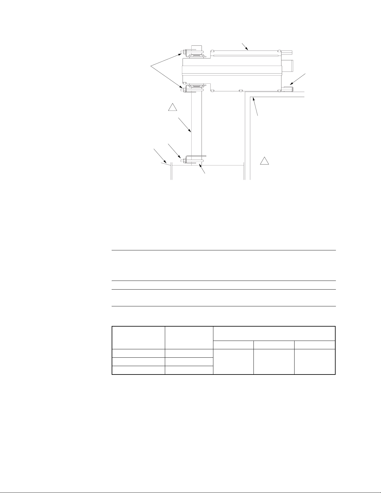
AM-753
Universal
Mounting Clamp
Assemblies
Actuator
Anti-rotation
Bracket
(included with
actuator)
AM-676
Universal Shaft
Extension
Duct
1
V-clamp
Figure-8 Installation of Universal Shaft Extension.
Wiring Requirements Control and Power Leads
Remove blue plastic thread protectors before installing conduit fittings. See Figure-1 through
Figure-1 for typical wiring applications and Table-3 for maximum wire lengths.
Caution:
powered by transformers used to power other devices utilizing non-isolated full-wave
rectifier power supplies. Refer to
Half-Wave Rectifier Devices from a Common Transformer
The 24 Vac model contains a half-wave rectifier power supply and must not be
Mounting Surface
1 The AM-676 extends the
damper shaft approximately
Damper Shaft
9" (229 mm).
EN-206 Guidelines for Powering Multiple Full-Wave and
, F-26363, for further information.
Note:
Class 2 control and power lead wiring must be routed separately from line voltage
wiring and any other non-class 2 circuits.
Table-3 Control and Power Wiring Data.
Actuator
Voltage
24 Vac MA40-7173
120 Vac MA40-7170
240 Vac MA40-7171
Part
Number
Maximum Wire Run in ft. (m)
(5% Voltage Drop)
14 AWG 16 AWG 18 AWG
1165
(355)
733
(223)
461
(141)
12 © Copyright 2006 TAC All Rights Reserved. F-26742-2
Page 13

CHECKOUT
THEORY OF OPERATION
This procedure is for checking out a normally closed actuator that is typically mounted
unpowered. It is possible to mount the actuator with power applied for special applications.
Note:
To check out a normally open actuator the procedure is the same as below, except
the initial position is open and the powered position is closed.
After the entire system has been installed and the actuator has been powered up, the
following check can be made for proper system operation. Check for correct operation of the
damper while actuator is being stroked.
1. Apply power to the actuator.
2. Set the controller to cause the actuator to drive open.
3. Check to see that the actuator travels to the full-open position.
4. Remove power from actuator to cause the actuator to drive closed.
5. Check to see that the actuator travels to the fully closed position.
Note:
If anticipated damper operation does not occur, verify the Long Damper Shaft or
Short Damper Shaft mounting procedures. Also, verify that the controller has the proper
action (direct or reverse) to match the damper required operation.
The actuator is, by means of dual mounting clamps, directly mounted onto the damper shaft.
The anti-rotation bracket supplied with the actuator prevents lateral movement of the
actuator. The damper actuator is not provided with and does not require, any limiting
switches, but is electronically protected against overloading.
The angle of rotation is electronically limited to 93° ±1°. When reaching the damper or
actuator end position, the motor stops automatically. The position of the actuator is indicated
by means of scale reading 0 to 95°.
MAINTENANCE
FIELD REPAIR
Regular maintenance of the total system is recommended to assure sustained optimum
performance. The MA40-717X actuator is maintenance free.
None. Replace with functional actuator.
F-26742-2 © Copyright 2006 TAC All Rights Reserved. 13
Page 14
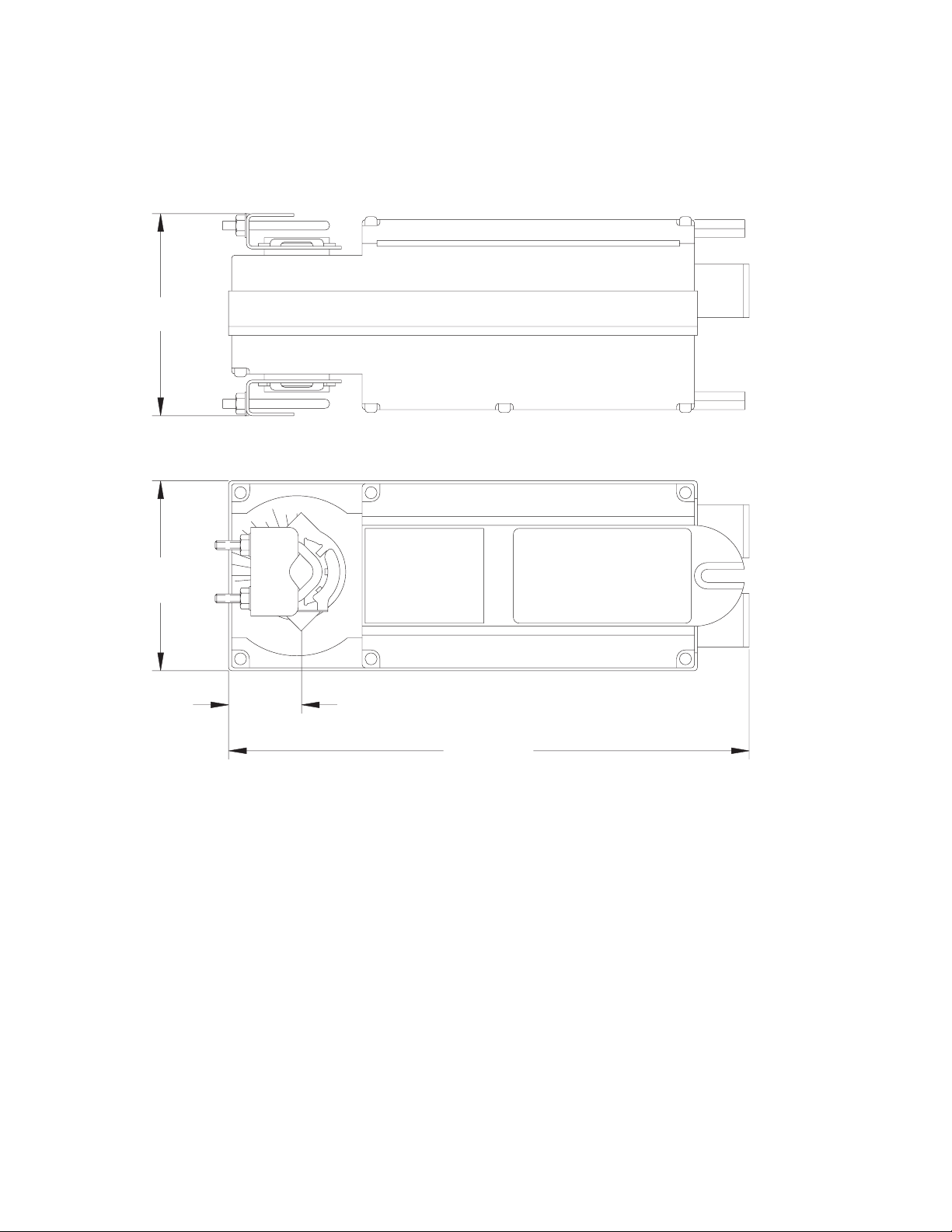
DIMENSIONAL DATA
4"
(102)
Figure-9 dimensions are in inches (mm).
R
4"
(102)
1-27/64"
(36)
10-27/32" (275)
Figure-9 MA40-717X Damper Actuator.
14 © Copyright 2006 TAC All Rights Reserved. F-26742-2
Page 15

F-26742-2 © Copyright 2006 TAC All Rights Reserved. 15
Page 16

Copyright 2006, TAC
All brand names, trad emarks and registered
trademarks are the property of their respective
owners. Information contained within this
document is subject to change without notice.
F-26742-2
TAC
1354 Clifford Avenue
P.O. Box 2940
Loves Park, IL 61132-2940
www.tac.com
 Loading...