

Page 1
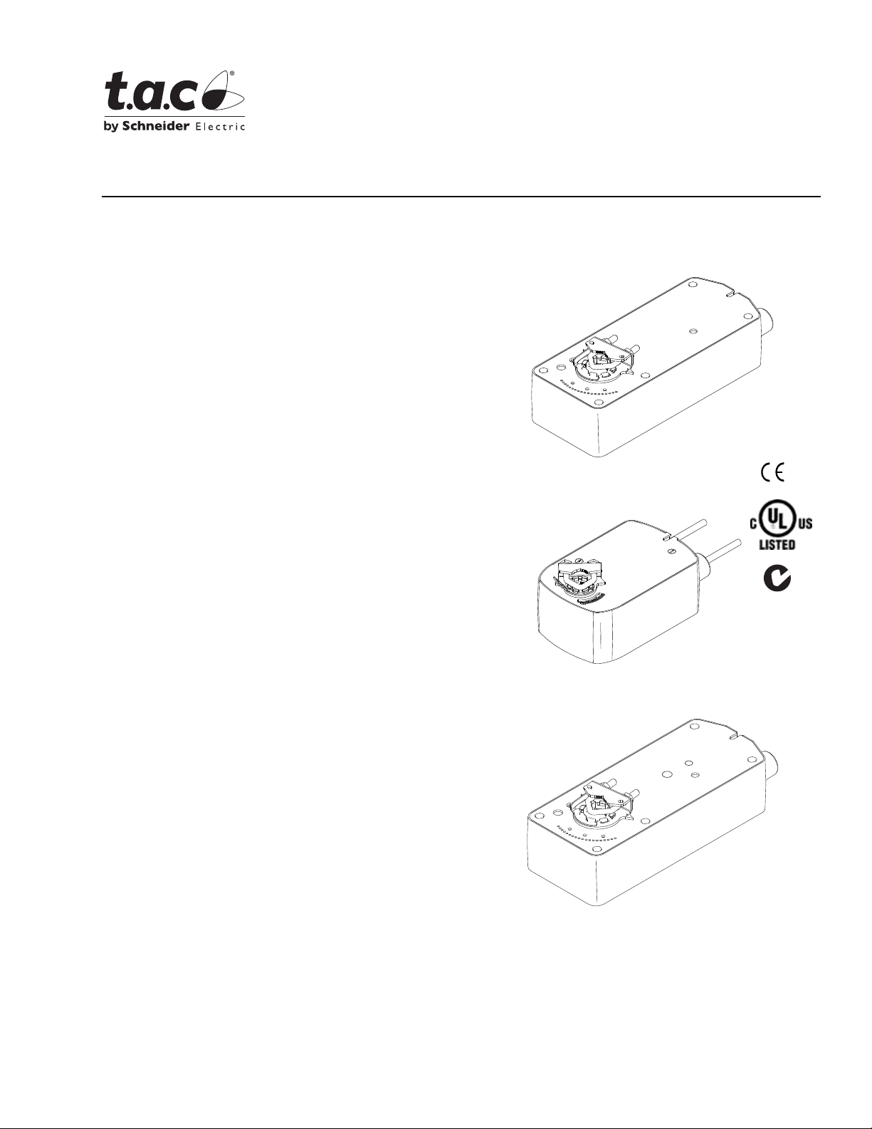
Application
TAC DuraDrive™ Direct Coupled Actuators are
designed to be used in both damper and valve control
applications. The follow general instructions are for
damper applications, refer to the Applicable Literature
table for valve literature.
The MA40-704X, MA4X-707X and MA4X-715X series
spring return actuators are used for the on-off, fail safe
control of dampers and valves in HVAC syste ms.
Features
MA40 -704X Series,
MA4X-707X Series,
MA4X-715X Series
TAC DuraDrive Series Spring Return
Two-Position Actuators
General Instructions
MA40-707X
MA40-715X
• Two-position actuator controlled by SPST controller
• 133 lb-in (15 N-m), 60 lb-in (7 N-m), and 35 lb-in
(4 N-m) torque models
• 24 Vac/DC, 120 Vac, and 230 Vac models
• Rugged die cast housings rated for NEMA 2 / IP54
• Overload protection throughout rotation
• Optional built-in auxiliary switch to provide for
interfacing or signaling
• Provides 95° of rotation
• Visual position indicator provided
• Provides true mechanical clockwise or
counterclockwise spring return operation for reliable
fail safe application and positive close-off in air tight
damper applications
• Direct mount to round or square damper shafts
• Rotation limiting available
• MA4X-7153 series actuators can be double-
mounted (gang mounting) to accommodat e high
torque application requirements
MA40-704X
MA41-707X
MA41-715X
• Five year warranty
• MA41-707X-XXX and MA41-715X - XXX e q ui pped
with manual override
Printed in U.S.A. 9-08 © Copyright 2008 TAC All Rights Reserved. F-26642-7
Page 2

Applicable Literature
F-Number Description Audience Purpose
Describ es the globe valve
actuator/linkage assembly’s features,
specif ications, and possible applications .
Provides step-by-step mounting
instructions.
Describ es the actuator/linkage/ball valve
assembly’s featur es, speci fications, and
possible applications. Provides step-bystep mounting instructions.
Provides actuator specifications and part
number cross referencing of phased out
actuator s wit h the new TA C di rect- cou pled
actuators.
Provides part number cross referencing of
phased ou t globe and ball valve
assemblies with the new TAC directcoupled actuators.
Descri bes TAC approved water tr ea tm en t
practices.
Provides charts, equations, and diagrams
to assist in the configuration of valve
system applications. TOOL-150, valve
sizing slide rule may be purchased
separately.
F-26750
F-26751
F-26646
F-26752
F-26080 EN-205 Water System Guidelines
F-13755 CA-28 Control Va lve Sizing
F-11080 Valve Selection Chart Water
F-11366 Valve Selection Chart Steam (two-way valves only)
MX40-6XXX-2XX, MX4X-7XXX-2XXSeries
Actuator/Linkage Assemblies General Instructions
VX-2000 Series Ball Valve Assembly Insta llations
Instructions
MX4X-7XXX, MX40-6XXX Series TAC DuraDrive
Actuator Selection Guide
VX-2000, VX-7000 Series
Ball/Linked Gl ob e Linked Valve A s se mb li es
Actuator/Linkage Assemblies Selection Guide
– Sales Personnel
– Application Engineers
–Installers
– Service Personnel
– Start-up Technicians
– Sales Personnel
– Application Engineers
–Installers
– Service Personnel
– Start-up Technicians
– Sales Personnel
– Application Engineers
–Installers
– Service Personnel
– Start-up Technicians
– Sales Personnel
– Application Engineers
–Installers
– Service Personnel
– Start-up Technicians
– Application Engineers
–Installers
– Service Personnel
– Start-up Technicians
– Application Engineers
–Installers
– Service Personnel
– Start-up Technicians
2 © Copyright 2008 TAC All Rights Reserved. F-26642-7
Page 3

SPECIFICATIONS
Actuator In puts
Control Signal: On-off, spring return. SPST control contacts or Triacs (500 mA rated).
Power Input: See Ta ble-1. All 24 Vac cir cuits are Cl ass 2. All circuits 30 Vac and above are
Class 1.
Connections: 3 ft. (91 cm) appliance cables, 1/2 in. conduit connector. For M20 Metric
conduit, use AM-756 adaptor.
Actuator Outputs
Electrical:
Auxiliary Switches,
MA4X-715X-502 and MA4X-7 07X-502 Two SPDT 7A (2.5A) @250 Vac, UL listed;
one fixed @ 5° and one adjustable 25 to 85°.
MA40-7040-501 and MA40-7041 -501 One SPDT 6A (1.5A) @250 Vac, UL listed;
adjustable 0 to 95° (0 to 1 scale).
MA40-7043-501 One SPDT 6A (1.5A) @24 Vac, UL li sted; adjustable 0 to 95°
(0 to 1 scale).
Mechanical:
Stroke, Angle of rotatio n 95° ± 5 ° maximum. Adjustabl e 30° to 95° with AM-689 install ed
on MA4X-715X or MA4X-707X series. Stroke limiter is standard on MA40-704X series.
Damper Shaft Clamp,
MA40-704X The factory installed universal clamp is used for shafts up to 5/8”
(15 mm) di ameter or up to 1/ 2" (13 mm) squa re. AM -710 acc esso ry clamp is requ ired
when mounting actuat ors to shafts up t o 3/4" (19 mm) diameter or up to 1/2" (13 mm)
square.
MA4X-715X or MA4X-707X The fact ory installed universal clamp is used for shafts
up to 3/4" (19 mm) diam eter or up to 1/2" (13 mm) square. AM-687 accesso ry clamp
is required when mounting actuators to shafts up to 1.05" (27 mm) in diameter or up
to 5/8" (15 mm) square.
Position Indicator, Visual indicator.
MA4X-715X and MA4X-707X, -5 to 90°
MA40-704X, 0 to 1 (0 is spring return position).
Nominal Damper Area, Actuator sizing should be done in accordance with damper
manufacturer’s specification.
Direction of Rotation, Clockwise or counterclockwise rotation determined by actuator
mounting.
Manual Override, MA41-707X and MA41-715X rotation is adjustable from -5
using manual override crank.
(-5° is spring return position).
o
to 85o
Environment
Ambient Temperature Limi ts:
Shipping & Storage, -40 F to 16 0°F (- 40 to 71°C ) .
Operating, -22 to 140°F (-30 to 60°C).
Humidity: 15 to 95% RH, non-condensing.
Location:
MA4X-715X and MA4X-707X, NEMA 1 (IEC IP30). NEMA 2 (IEC IP54) with conduit
connector in the down position.
MA40-704X, NEMA 2 (IEC IP54) no restrictions.
Agency Listings
UL 873: Underwriters Laboratories (File # E9429 Categor y Tem perature-Indicating and
Regulating Equipment).
CUL: UL Listed for use in Canada by Underwriter s Laboratories. Canadian Standards
C22.2 No. 24.
European Community: EMC Directiv e (89/336/ EEC). Low Volta ge Direct ive (72/23/ EEC).
Australia: Thi s product meet s requirem ents to bear the C-Tick Mark ac cording t o the terms
specified by the Com mu nications Authority under the Radiocommunications Act 1992.
F-26642-7 © Copyright 2008 TAC All Rights Reserved. 3
Page 4

Table-1 Model Chart.
Approximate
Actuator Power Input
Part Numbers
Voltage
VA Watts
Running
50 Hz
60
Hz
50 Hz60
Hz
DC
Amps
Holding
50 Hz 60 Hz
MA40-7153
MA40-7153-
502
MA41-7153 No Yes
MA41-7153-
24 Vac
± 20%
22-30
Vdc
9.8 9.7 7.5 7.5 0.29 2.8 2.8
502
MA40-7150
MA40-7150-
502
MA41-7150 No Yes
120 Vac
±10%
11.7 10.0 8.8 8.4 — 3.6 5.0
MA41-7150502
MA40-7151
MA40-7151-
502
MA41-7151 No Yes
230 Vac
±10%
15.5 10.6 9.5 8.5 — 4.6 3.3
MA41-7151502
MA40-7073
MA40-7073-
502
MA41-7073 No Yes
MA41-7073-
24 Vac
± 20%
22-30
Vdc
4.8 4.8 3.2 3.2 0.13 0.8 0.8
502
MA40-7070
MA40-7070-
502
MA41-7070 No Yes
120 Vac
±10%
10.7 5.6 4.2 3.6 — 2.0 1.2
MA41-7070502
MA40-7071
MA40-7071-
502
MA41-7071 No Yes
230 Vac
±10%
17.0 8.0 5.1 4.0 — 2.7 1.4
MA41-7071502
MA40-7043 24 Vac
MA40-7043-
501
MA40-7040
MA40-7040501
MA40-7041
MA40-7041-
501
a
Timing was measured with no load applied to the actuator.
b
De-rating is required at low temperatures.
c
One adjustable from 25 to 85° rotation and one set to operate @ 5° fixed.
d
One adjustable from 0 to 95° rotation (0 to 1 scale).
± 20%
22-30
Vdc
120 Vac
±10%
230 Vac
±10%
4.4 4.4 2.9 2.9 0.11 0.8 0.8
6.4 4.3 3.8 3.4 — 1.6 1.2
5.8 4.6 4.1 3.9 — 1.5 1.2
Auxiliary
Switch
No
c
Two
c
Two
No No
c
Two
c
Two
No No
c
Two
c
Two
No
c
Two
c
Two
No No
c
Two
c
Two
No No
c
Two
c
Two
No
d
One
No No
d
One
No No
d
One
Timing in
Seconds @ 70°
Powered
(21°C)
a
Spring
Return
<190 <30 133 (15) 350 (40)
<80 <40 60 (7) 2 50 (28)
<50 <26 35 (4) 1 50 (17)
Output Torq ue
Rating
lb-in (N-m)
Minimum
b
Maximum
Stall
Manual
Override
No
No
Yes
No
Yes
No
Yes
No
No
Yes
No
Yes
No
Yes
No
No
No
No
4 © Copyright 2008 TAC All Rights Reserved. F-26642-7
Page 5

ACCESSORIES
For use with MA4X-7XXX:
AM-671 Universal Mounting Bracket, AM-693 is required
AM-672 Universal Mounting Bracket, AM-693 is required
AM-673 Mounting Bracket
AM-674 Weathe r Shield
AM-675 Base Mounting Plat e for AM-674
AM-676 Unive rsal Shaft Extension
AM-714 Weather Shield (polycarbonate)
AM-756 Metric Conduit Adapter M20 x 1.5 to 1/2" NPT
AM-761 7-inch Anti-rotation Bracket
AM-762 9-inch Anti-rotation Bracket
For use with MA40-7043:
AM-709 Position Indicator and Stroke Limiter
AM-710 Universal Clamp for up to 3/ 4" diameter shafts
AM-711 Crankarm for up to 1/ 2" round sh aft
AM-712 Crankarm Adapter Kit
AM-713 Mounting Bracket for Honeywell Mod IV, M6415
type ac tua to r s and ne w ins tal la tions
AM-715 Crankarm Adapter Kit for Honeywell Mod IV,
M6415 type actuators and new installations
For use with MX4X-7073, MX4X-7153
AM-686 Damper Position Indicator
AM-687 Universal Clamp for up to 1.05" (27 mm) diameter
shafts
AM-688 Replacement Universal Clamp
AM-689 Rotation Li miter
AM-690 Crankarm for round shafts up to 3/4" (19 mm)
AM-691 Crankarm for jackshafts up to 1.05" (27 mm)
AM-692 V-bolt Kit for AM-690 and AM-691 Crankarm
AM-693 Damper Linkage Kit
AM-758 Short "U" Mounting Br acket
AM-759 Tall "U" Mounting Bracket
AM-760 Slotted "L" Mounting Brack et
AM-763 1/8" Hex C rank for Manual Override
F-26642-7 © Copyright 2008 TAC All Rights Reserved. 5
Page 6
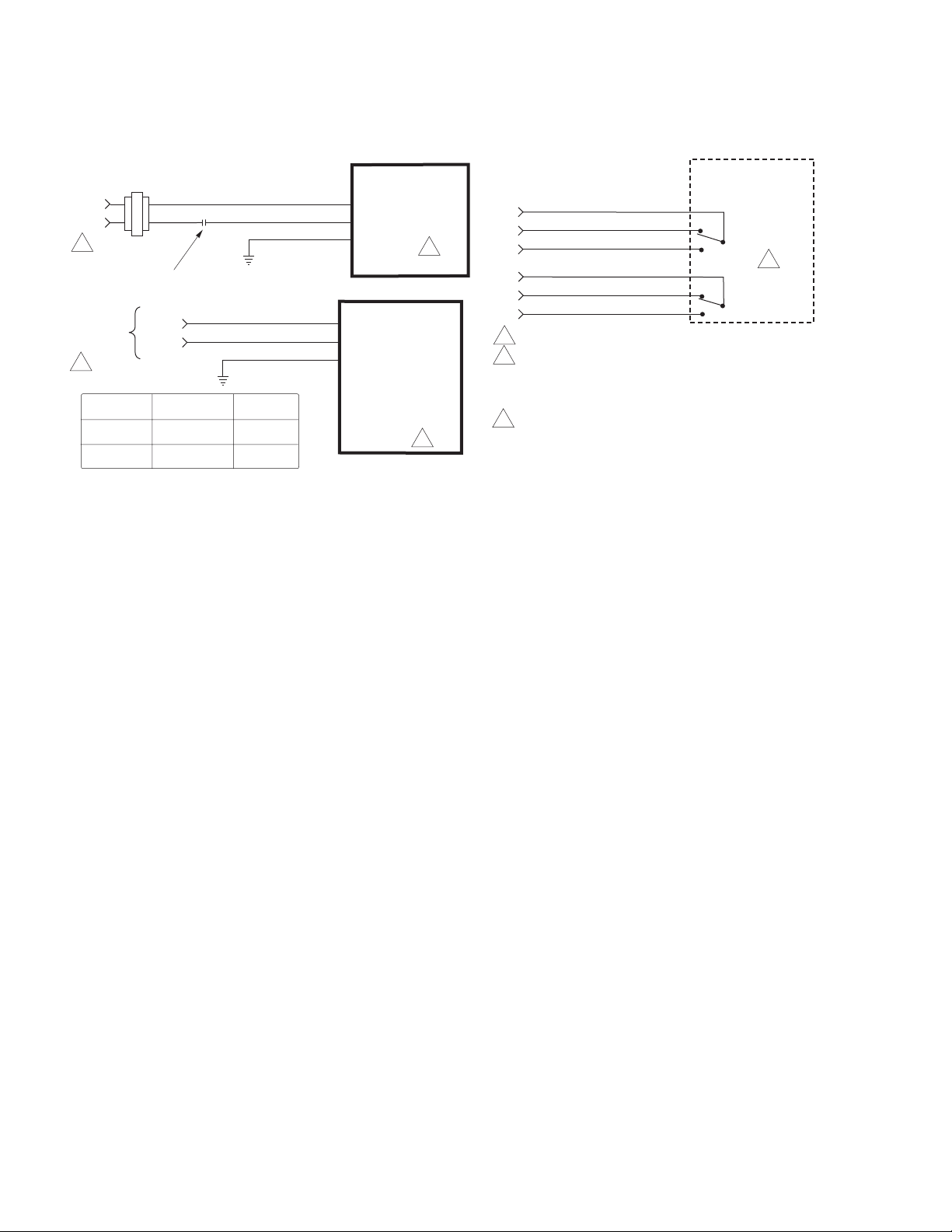
TYPICAL APPLICATIONS (wiring diagrams)
Figure-1 through Figure-3 illustrat e typi cal wiring diagrams for spri ng return floating
actuators. See Table-1 for model selection.
24 Vac Transformer
or 22-30 Vdc
Line
Volts
1
SPST Control Contact
120 Vac or
230 Vac
1
Voltage Wire 1 Wire 2
120 Vac White Black
230 Vac Blue
L1 N
L2 H
Wire No. 1
Wire No. 2
Blk
Red
Brown
Com
Hot (+DC)
Grn/Yel
Com
Hot
Grn/Yel
Optional Auxiliary
MA4X-7153
MA4X-7073
MA4X-7153-502
MA4X-7073-502
2
MA4X-7150
MA4X-7151
MA4X-7070
MA4X-7071
MA4X-7150-502
MA4X-7151-502
MA4X-7070-502
MA4X-7071-502
2
MX40-707X-502 and MX40-715X-502 units manufactured prio r to the date code 0141
(October 6, 2001) u s ed the following color coding for the auxiliary switches:
Auxiliary Switch 1
Orange: Fixed auxiliary switch common (com)
Yellow: Fixed auxiliary switch normally closed (NC)
Violet: Fixed auxiliary switch normally open (NO)
Auxiliary Switch 2
Orange/w hite: Adjustable auxiliary switch common (com)
Violet/white: Adjustable auxiliary switch nor mally closed (NC)
Yellow/white: Adjustable auxiliary switch normally open (NO)
The label information on these units is incorrect. If replacing these units, the auxiliary switch
operation of the replacement actuator will b e per the product label.
1 Provide overload protection and disconnect as required.
2 Actuators mounted on separate shafts may be wired in
3 For end position indication, interlock control, fan startup,
Switches
Org
Vio
Yel
Org/Wht
Vio/Wht
Yel/Wht
parallel. All actuator black wires are connected to the
transformer common and all red wires are connected to
the hot lead. Power consumption must be observed.
etc., MA4X-715X-502, and MA4X-707X-502 models
incorporate two built-in auxiliary switches.
Com
NC
NO
Com
NC
NO
Aux Switches
MA4X-7XXX-502
Aux Switch 1
25 to 85°
Adjustable
3
Aux Switch 2
5° Fixed
Figure-1 Typical Wiring Diagram for 24 Vac Basic and Double Auxi liary Switch Models.
6 © Copyright 2008 TAC All Rights Reserved. F-26642-7
Page 7
120 Vac or
230 Vac
1
L1 N
L2 H
Wire No. 1
Wire No. 2
Green/Yellow
Neutral
Hot
MA40-7040
MA40-7041
2
120 Vac or
230 Vac
1
Auxiliary Switch 1
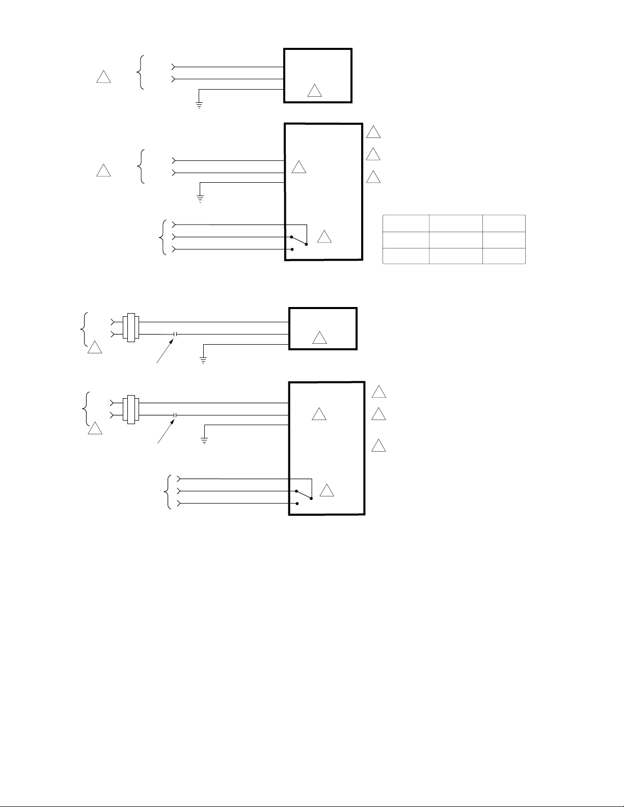
Figure-2 Typical Wiring Diagram for 120 Vac or 230 Vac Basic and Single Auxil iary Switch Models.
Line
Volts
1
Line
Volts
1
SPST Control Contact
Auxiliary Switch 1
24 Vac
SPST Control Contact
24 Vac
L1 N
L2 H
Wire No. 1
Wire No. 2
Orange
Violet
Yellow
Black
Red
Black
Red
Orange
Violet
Yellow
Neutral
Hot
Green/Yellow
COM.
N.C.
N.O.
Common
Hot
Green/Yellow
Common
Hot
Green/Yellow
N.C.
N.O.
MA40-7040-501
MA40-7041-501
2
0 to 1 Scale
MA40-7043
(1)
(2)
MA40-7043-501
Adjustable
3
2
2
0 to 1 Scale
Adjustable
3
1 Provide overload protection and disconnect as
required.
2 Actuators may be wired in parallel. Power
consumption must be observed.
3 For end position indication, interlock control, fan
startup, etc., MA40-704X-501 model incorporates
one built-in auxiliary switch. See Specifications
section for details.
Voltage Wire 1 Wire 2
120 Vac White Black
230 Vac Light Blue Brown
1 Provide overload protection and disconnect as
required.
2 Actuators may be wired in parallel. Power
consumption must be observed. Actuator may also
be powered by 24 Vdc.
3 For end position indication, interlock control, fan
startup, etc., MA40-7043-501 model incorporates
one built-in auxiliary switch. See Specifications
section for details.
Figure-3 Typical Wiring Diagram for 24 Vac Basic and Single Auxiliary Switch Models.
INSTALLATION
Inspection Inspect the pack age for damage. If damaged, notify the appropriate carrier immediately. If
undamaged, open the package and inspect the device for obvious damage. Return
damaged products.
Requirements • Job wiring diagrams
• Tools (not provided):
– #8 sheet metal screws
– 10mm open end wrench or socket wrench
– 7/16 inch, open end wrench or socket wrench
– 1/8 inch, allen wrench
– Appropriate screwdriver(s)
• Appropriate accessories
• Training: Installer must be a qualified, experienced technician
F-26642-7 © Copyright 2008 TAC All Rights Reserved. 7
Page 8

Precautions General
Warning:
• Electrical s hock hazard! Disc onnec t the power su ppl y (l ine power ) bef or e inst alla tion to
prevent electric shock and equipment damage.
• Make all connections in accordance with the job wiring diagram and in accordance
with national and loc al el ectrical codes.
Caution:
• Avoid electrical noise interference. Do not ins tal l near large contactors, electrical
machinery, or welding equipment.
• Do not drill ho les i n actuat or body. S ix pre -dril led h ole s are l ocated on ea ch side , un der
the label, to accept #10-24 thread-forming screws for mounting accessories.
Use copper conductors only.
Caution:
override.
The MX41-707X and MX41-715X actuators are equipped with a manual
• The manual override is to be used only when power is not applied to the unit.
• If the universal cl am p is not set to 0° on the position indicator, manually wind the
actuator in the dire ction indicated with hex wrench f rom -5° to 0° and lock with a
screwdriver.
• When operating manual override, back off 5° from ful l open mecha nical stop to ensu re
proper release.
• Do not attempt to use t he manu al over ride wi th act uators mounted in tandem . Damage
to the gear train may occur.
Federal Communications Commission (FCC)
Note:
This equipment has been tested and found to comply with the limits for a Class B
digital device, pursuant to Part 15 of the FCC Rules. These limit s are designed to provide
reasonable protection against harmful interference in residential installations. This
equipment generates, uses, and can radiate radio frequency energy and may cause
harmful interfer ence if not installed and used in accordance with the instruct ions. Even
when instructions are followed, there is no guarantee that interference will not occur in a
particular—Whi ch can be determined by turning the equipment off and on—the user is
encouraged to try to correct the interference by one or more of the following measures:
• Reorient or relocat e the r eceiving antenna.
• Increase the separation between the equipment and receiver.
• Connect the equipment to an outlet on a ci rcui t differ ent fro m that to whic h the receive r
is connected.
• Consult the dealer or an experienced radio/television technician for help.
Canad i an Department of Comm unica t i ons (DOC)
Note:
This Class B digital apparatus meets all requirement s of t he Canadian InterferenceCausing Equipment Regul ations.
Cet appareil numerique de la classe B respecte toutes les exi gences du Reglement sur le
material broilleur du Canada.
European Standard E N 55022
Warning:
environment this product may cause radio interference in which case the user may be
required to take adequate measures.
Location
8 © Copyright 2008 TAC All Rights Reserved. F-26642-7
Caution:
explosive vapor s are present.
This is a Class B digital (Eur opean Classification) product. In a domestic
Avoid locations where excessive moisture, corrosive fumes, vibration, or
Page 9
Mounting
Caution:
To remain in NEMA 2/IP54 compli ance, the MA4X-715X and MA4 X-707X series
actuators should be mounted with conduit end down.
Mount the TAC DuraDrive Actuator directly on the damper shaft in locations that clear the
maximum dimensi ons of the actuator cas e and allow the actuator to be mounted flush to the
surface of the terminal box and perpendicular to the damper shaft.
Note:
Some terminal boxes have sheet metal screw heads or other protrusions near the
damper shaft. In these cases, a spacer or shim may be added under the anti-rotation
bracket of the actuator to make the actuator perpendicular to the shaft.
Damper Actuator Sizing
Correct sizing of the actuator is necessary for proper control of dampers. The area of
damper that can be controlled by a given actuator is dependent upon the type of damper,
the quality of the damper, the pressure drop acr oss the damper in the closed position, and
the velocity of the air flow through the damper. To obtain actual damper torque
requirements, contact the damper manufact urer.
Damper Shaft Sizing
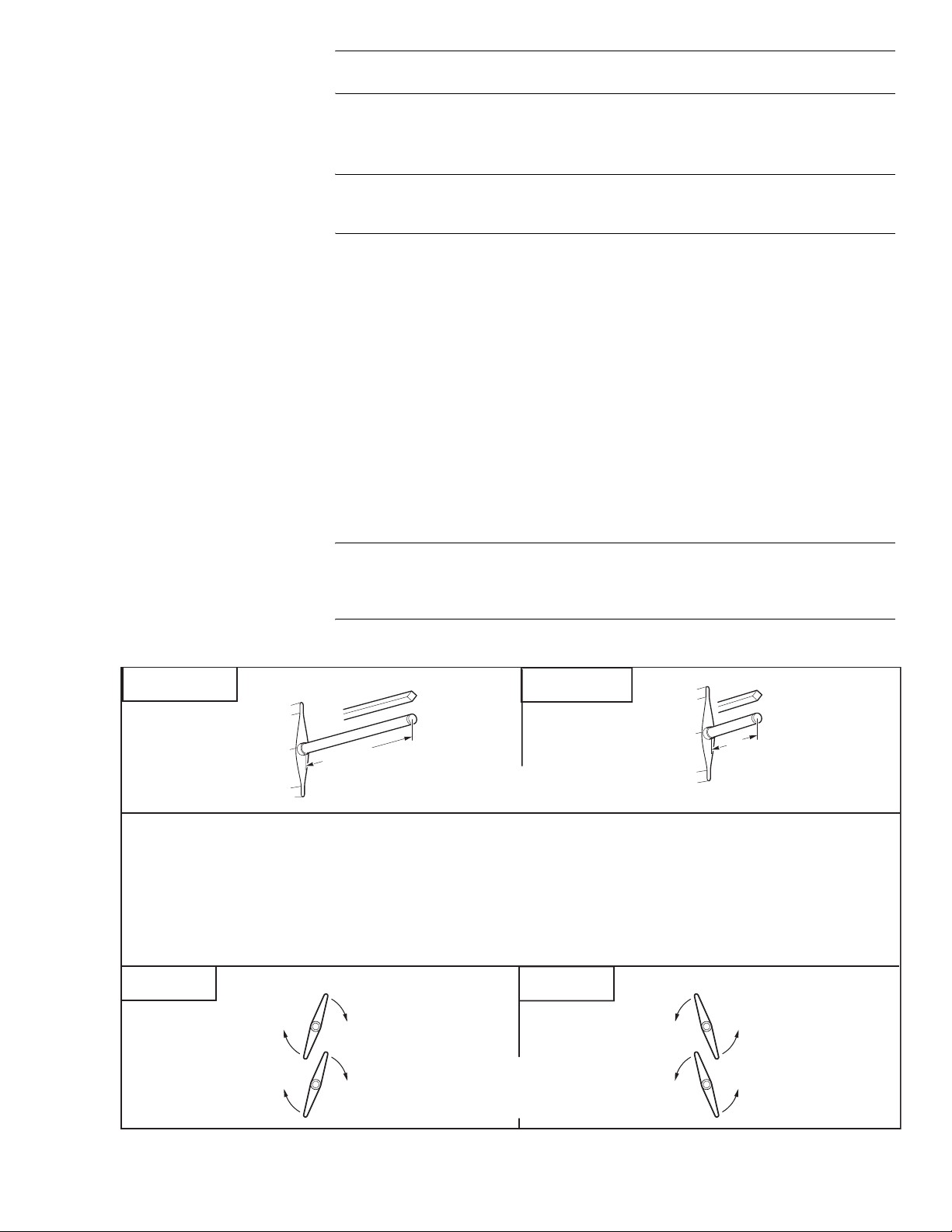
Use the “Long Damper Shaft ” mounting instructions if the damper shaft is at least 3-1/2"
(90 mm) long.
Use the “Short Damper Shaft” mounting instructions if the damper shaft is shorter than
3-1/2" (90 mm) or the area around the damper shaft is too narrow to allow standard
mounting, as described in the “Short Damper Shaft” mounting section.
MA40-704X Series Installation
Note:
The MA40-704X series actuator comes equipped with st andard universal mounting
clamp. For damper shafts larger than 5/8" (16 mm) in diameter, the AM-710 universal
mounting clamp is r equired (order separately). The AM-710 clamp accommodates shafts
sizes up to 3/4" (19 m m) diameter shafts.
Long Shaft
Min. 3 1/2" (90 mm)
3/8" to 3/4" Diameter (10 mm to 20 mm)
3/8" to 1/2" Square (10 mm to 13 mm)
Move the damper to its normal position. Verify the controller action is set to match the
damper application.
Normally closed damper: when damper is closed, actuator position indicator should
be at 0°. When damper is open, actuator position indicator should be at 90°.
Normally opened damper: when damper is open, actuator position indicator should
be at 0°. When damper is closed, actuator position indicator should be at 90°.
Short Shaft
Min. 3/4" (20 mm)
A - Left
F-26642-7 © Copyright 2008 TAC All Rights Reserved. 9
Shaft Rotates
Clockwise
To Open
This step determines
shaft rotation. Linkage
may change damper direction.
A - Right
Shaft Rotates
Counterclockwise
To Open
Page 10
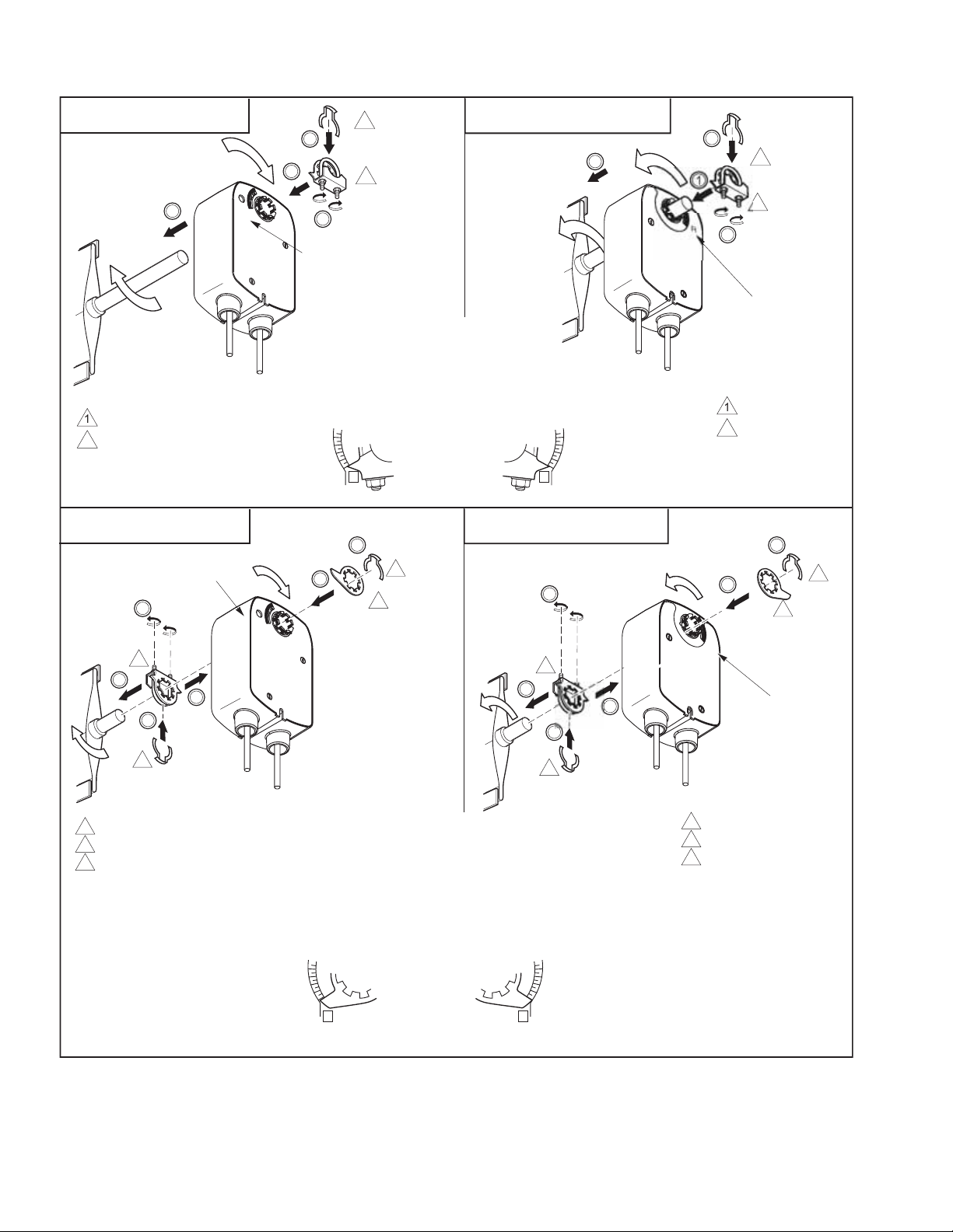
U
l
m
.
.
l
.
.
B - Left - Long Shaft
R
niversa
ounting clamp
Retaining clip
2
1
"L" Marker
2
B - Right - Long Shaft
2
L
3
2
1
1
4
"R" Marker
1. Assemble mounting clamp.
2. Assemble retaining clip.
3. Place actuator over shaft.
4. Hand tighten clamp nuts.
.4
.2
0
Correct clamp mounting
position if actuator is
L
in normal spring
return position
(before preload)
.4
.2
0
R
niversa
ounting clamp
Retaining clip
B - Left - Short Shaft
"L" Marker
4
1
1
1 Universal clamp.
2 Retaining clip.
3 Damper position indicator.
B - Right - Short Shaft
B
A
R
L
2
3
4
1
L
A
R
1
1 Universal clamp.
A. Assemble damper position indicator.
B. Assemble retaining clip.
2 Retaining clip.
3 Damper position indicator.
1. Position mounting clamp.
2. Assemble retaining clip.
3. Slide actuator over shaft.
4. Hand tighten clamp nuts.
.4
.2
0
Correct pointer mounting
position if actuator is
in normal spring
L
return position
(before preload)
.4
.2
0
R
B
2
3
"R" Marker
10 © Copyright 2008 TAC All Rights Reserved. F-26642-7
Page 11
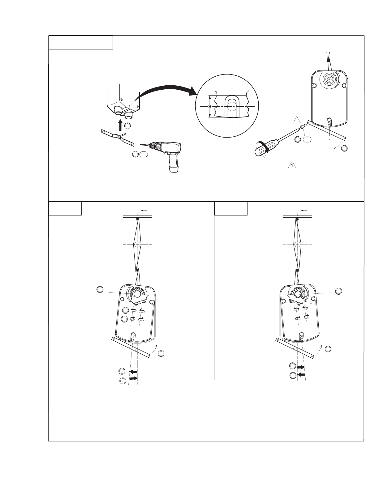
C - Left and Right
#8 S
l
w
D- Left
5. Center bracket in slot.
6. Drill two holes.
7. Start one screw.
8. Swing bracket down.
Universal Bracket in the Slot
Center the
1
.8
.6
.4
.2
0
1/2
1/2
1
5
x 1
7
8
x 2
6
heet Meta
cre
C
L
Centerline
D- Right
C
L
Centerline
10
0°
11
13
12
1
.8
.6
.4
.
2
0
L
1
.8
.6
.4
.2
0
9
12
12
14
5°
1
1
.8
.8
.6
.6
.4
.4
.2
.2
0
R
0
0°
10
9
14
5°
11
13
9. Loosen clamp nuts.
10. Check that the shaft is in full zero position.
11. Swing actuator
5° in the direction of travel. Do not move shaft.
12. Tighten clamp nuts to 4 to 6 lb-ft (5.4 to 8.2 N-m) of torque.
13. Move bottom of actuator back into position.
14. Pivot bracket back into position.
F-26642-7 © Copyright 2008 TAC All Rights Reserved. 11
Page 12
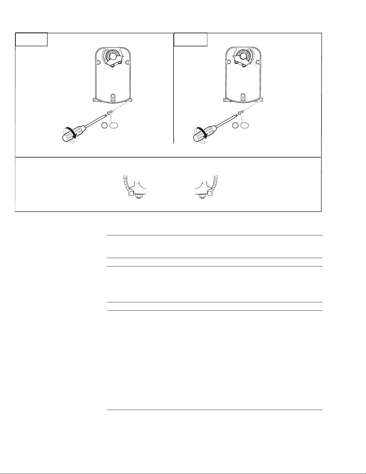
E- Left
E - Right
1
.8
.6
.4
.2
0
L
9
12
1
.8
.6
.4
.2
0
R
15
x 2
15
x 2
15. Tighten bracket screws.
.4
.2
0
L
Correct clamp mounting
position
(after 5˚ preload)
.4
.2
0
R
MA4X-707X and MA4X-715X Series Installation
Caution:
on each side, under the label, to accept #10-24 thread-forming screws for mounting
accessories.
Note:
universal mount ing clamp installed. For dam per shafts larger than 3/4" (19 mm ) i n
diameter, the AM-687 universal mounting clamp is requi red (order separately). The
AM-687 clamp accommodates round shaft sizes up to 1.05" (27 mm) in diameter or 5/8"
(16 mm) square shafts.
Do not drill additiona l holes i n the actua tor body. Six pre- drille d holes are located
The MA40-707X and MA40-715X ser ies actuators come equipped wit h standard
Caution:
The MA41-707X and MA41-715X act uators are equipped with a manual
override.
• The manual overrid e to be used only when power is not applied to the unit.
• If the universal clamp is not set to 0° on the position indicator, manually wind the
actuator in the dir ection indicated with hex wrench from -5° to 0° and lock with a
screwdriver.
• When operating manual over ride, back off 5° from full open mechanical stop to ensure
proper releas e.
• Do not attempt to us e the manual over ride with act uator s mount ed in t andem. Dam age
to the gear train could occur.
• Using power tools to adj ust the manual override will cause dama ge to the gears.
• To unlock manual override without power, crank the manu al override in the direction
indicated a minim um of 5°.
12 © Copyright 2008 TAC All Rights Reserved. F-26642-7
Page 13
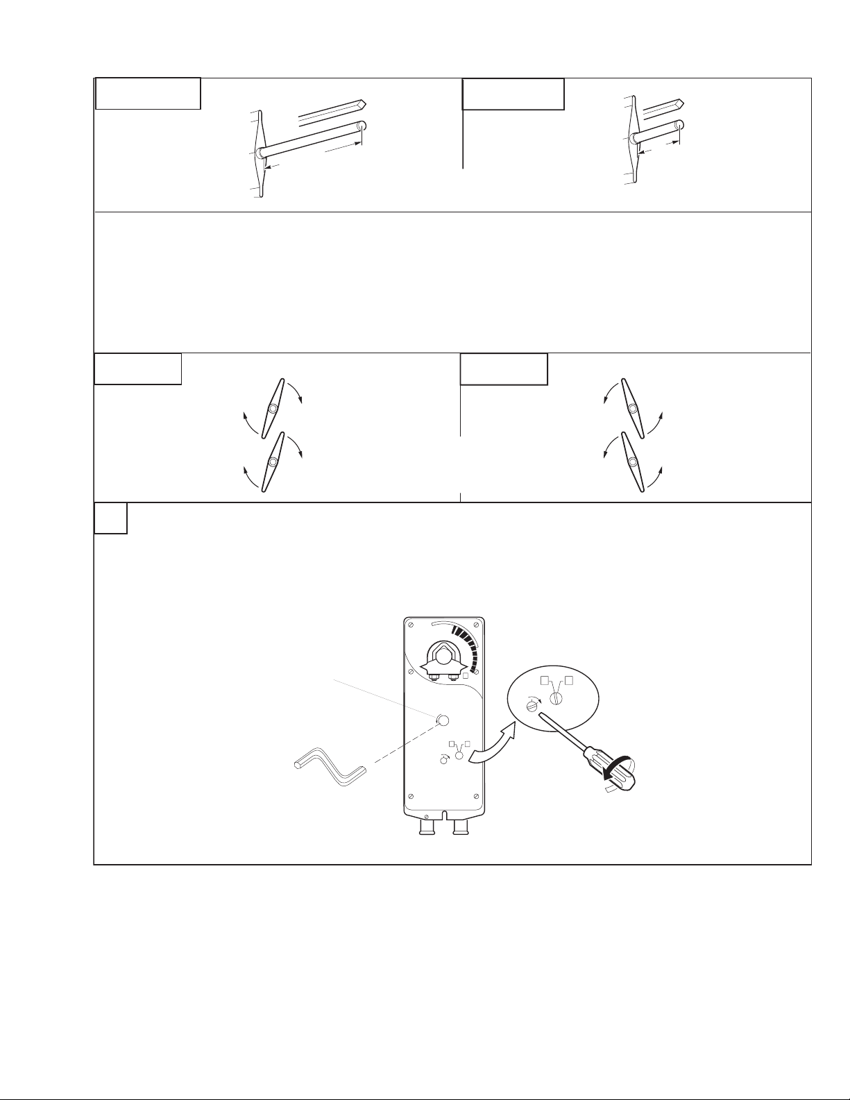
Long Shaft
Short Shaft
Min. 3 1/2" (90 mm)
3/8" to 3/4" Diameter (10 mm to 20 mm)
3/8" to 1/2" Square (10 mm to 13 mm)
Move the damper to its normal position. Verify the controller action is set to match the
damper application.
Normally closed damper: when damper is closed, actuator position indicator should
be at 0°. When damper is open, actuator position indicator should be at 90°.
Normally opened damper: when damper is open, actuator position indicator should
be at 0°. When damper is closed actuator position indicator should be at 90°.
A - Left
Shaft Rotates
A - Right
Clockwise
To Open
This step determines
shaft rotation. Linkage
may change damper direction.
For MA41-707X and MA41-715X only (manual override).
B
For MA40-707X and MA40-715X, proceed to step C.
Min. 3/4" (20 mm)
Shaft Rotates
Counterclockwise
To Open
If position indicator does not point to zero:Unlock the actuator.
Manual Override
Fully engage hex wrench
into manual override before
winding.
Caution: Do not crank the manual
override if power is applied
to the actuator.
Insert hex wrench into manual override.
0°
Crank the actuator so the indicator points to
.
Lock the actuator.
R
R
L
L
O
C
K
LOCK
R
L
Unlock
F-26642-7 © Copyright 2008 TAC All Rights Reserved. 13
Page 14
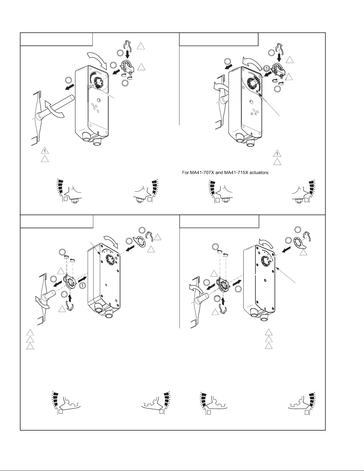
C - Left
:
sal
.
.
L
O
CK
l
.
.
- Long Shaft
R
3
niver
ounting clamp
Retaining clip
For MA40-707X and MA40-715X actuators
4
0
30
20
0
1
0
-5
L
Correct clamp mounting
position if actuator is
in normal spring
return position
2
1
"L" Marker
C - Right - Long Shaft
2
2
L
3
1
4
R
L
O
L
C
K
1. Assemble mounting clamp.
2. Assemble retaining clip.
3. Place actuator over shaft.
4. Hand tighten clamp nuts.
40
30
20
10
0
-
5
R
40
30
20
10
0
-5
L
Correct clamp mounting
position if actuator is
locked with 5° preload.
2
1
"R" Marker
niversa
mounting clamp
Retaining clip
40
-5
R
30
20
10
0
C - Left - Short Shaft
"L" Marker
4
1
1 Universal clamp.
2 Retaining clip.
3 Damper position indicator.
For MA40-707X and MA40-715X actuators:
40
30
20
10
0
-5
L
Correct pointer mounting
position if actuator is
R
L
in normal spring
return position
C - Right - Short Shaft
B
A
2
3
A. Assemble damper position indicator.
B. Assemble retaining clip.
1. Position mounting clamp.
2. Assemble retaining clip.
3. Slide actuator over shaft.
4. Hand tighten clamp nuts.
For MA41-707X and MA41-715X actuators:
0
4
0
3
20
10
0
-
5
R
B
L
A
4
3
R
1
1
"R" Marker
1 Universal clamp.
2 Retaining clip.
3 Damper position indicator.
40
3
0
20
10
0
-5
Correct pointer mounting
position if actuator is
locked at 5° preload.
L
0
4
30
20
10
0
-5
R
14 © Copyright 2008 TAC All Rights Reserved. F-26642-7
Page 15
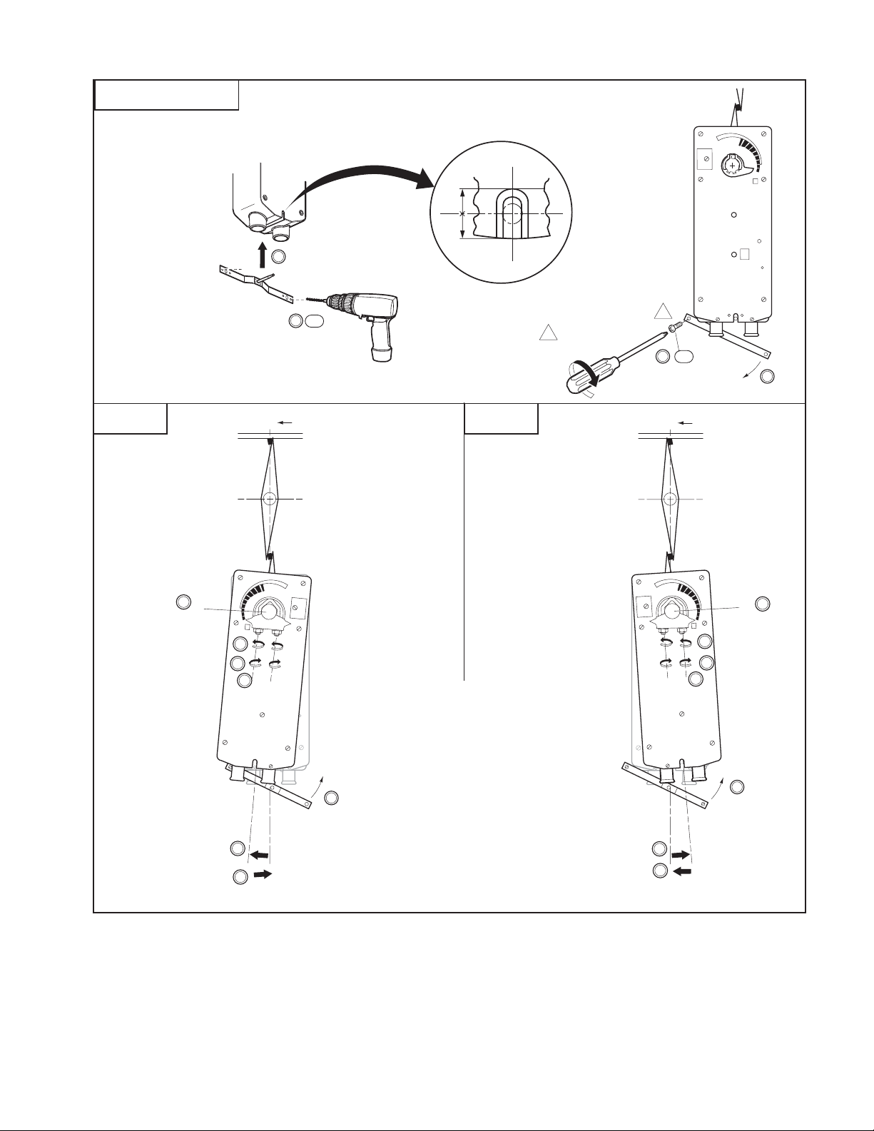
R
R
D - Left and Right
Universal Bracket in the Slot
Center the
R
1/2
1/2
5
x 2
6
5. Center bracket in slot.
6. Drill two holes.
7. Start one screw.
For MA41-707X and MA41-715X actuators, insert and tighten both screws.
8. Swing bracket down (MA40 actuator only).
E- Left E- Right
10
0°
C
Centerline
L
L
9
11
13
L
9. Loosen clamp nuts.
10. Check that the shaft is in full zero position.
#8 Sheet Metal
1
Screw
1
x 1
7
8
C
L
Centerline
10
0°
R
9
11
13
R
For MA41-707X and MA41-715X only:
11. Tighten clamp nuts to 8 - 10 ft-lb (11 - 14 Nm).
This completes the installation for MA41-704X
and MA41-715X.
15
15
For MA40-707X and MA40-715X only:
12
5°
12. Swing actuator
not move shaft.
13. Tighten clamp nuts to 8 - 10 ft-lb (11 - 14 Nm).
14. Move bottom of actuator back into position.
14
15. Pivot bracket back into position.
5° in the direction of travel. Do
12
5°
14
F-26642-7 © Copyright 2008 TAC All Rights Reserved. 15
Page 16
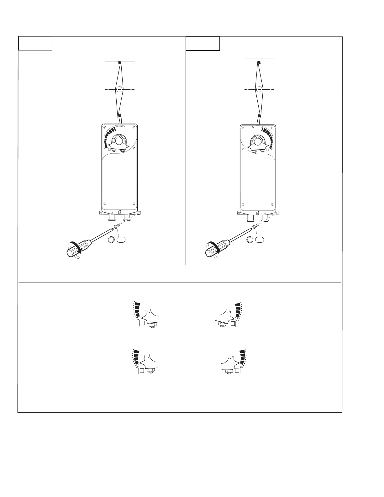
F- Left
F- Right
L
x 2
16
For MA40-707X and MA40-715X only:
16. Tighten bracket screws.
For MA40-707X and MA40-715X actuators:
40
30
20
10
0
-5
L
Correct pointer position
after mounting.
R
x 2
16
40
30
20
1
0
0
-5
R
For MA41-707X and MA41-715X actuators:
40
3
0
20
10
0
-5
Correct pointer position
after mounting.
L
40
0
3
2
0
10
0
-5
R
The lock on MA41-707X and MA41-715X will release on first power-up.
16 © Copyright 2008 TAC All Rights Reserved. F-26642-7
Page 17

Jackshaft Installation
(MA40-704X Series)
The MA40-704X actua tor is designed fo r use with jackshaf ts up to 3/4" (19 mm) in diameter .
In most applicat ions, the MA40-704X actuator may be mounted in the same manner as a
standard damper shaft application. If t he jackshaft diameter is larger than 5/8" (16 mm) in
diameter, the opti onal AM-710 universal clamp mu st be used.
(MA4X-715X and MA4X-707X Series)
The MA4X-715X and MA4X-707X actuator s are design ed for use with j ackshafts u p to 1.05"
(27 mm) in diameter. In most appli cations, the actuat or may be mounted in the same manner
as a standard damper sh aft ap plica tion. I f the jac kshaft diamet er is l arger t han 3/ 4" (19 mm)
in diameter, the optional AM-687 universal clamp must be used.
Multiple Actuator Mounting
If more t orque is requi red t han one ac tu ator can provi de a s econd ac tuator may be m ounted
to the damper shaft , usi ng the AM-673 multiple mounting br acket. See Figure-4.
Multiple actuators may be powered from one transfor m er provided the following rul es are
followed:
• The total current draw of the actuators (VA rating) i s les s than or equal to the rating of
the transform er and less than the rating of the control circuit.
• Polarity on the secondary of the transformer is strictly followed.
– All L2 wires from all actuators are connected to the common lead on the
transformer.
– All L1 wires from all actuators are connected to the hot lead.
Caution:
Mixing the L2 and L1 wires on one lead of t he tr ansformer may result in erratic
operation or fail ure of the actuator and/or controls.
Caution:
Do not attempt to use the manual over ride with actuators mounted in tan dem .
Damage to the gear train ma y occur.
Multiple actuators positioned by the same control signal may be powered from multiple
transformer s provided the following rule s are followed:
• The transformers are properly sized.
• All L2 wires from all actua tors are tied together and tied t o the negative lead of the
control signal.
Table-2 Power Wiring Color Code.
Part Number L1 L2
MA4X-7XX3
MA4X-7XX3-502
MA4X-7XX0
MA4X-7XXX-502
MA4X-7XX1
MA4X-7XXX-502
Red Black
Black White
Brown Light Blue
F-26642-7 © Copyright 2008 TAC All Rights Reserved. 17
Page 18
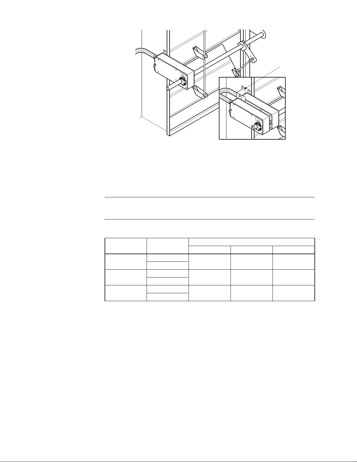
Figure-4 Mounting Multiple Actuators.
Wiring Requirements Control and P ower Leads
See Table-3 for power wiring data. Refer to Figure-1 through Fig ure- 3 for typical wiring
applications.
Note:
Class 2 control and power lead wiring must be routed separatel y from line voltage
wiring and any ot her non- class 2 ci rcui ts. Li ne volt age, auxi lia ry swit ch, and aux ili ary swit ch
leads must be connected to a class 1 circuit.
Table-3 Power Wiring Data.
MA-7501-502
AM-673
SIEBE
Actuator Voltag e Part Num be r
24 Vac
22-30 Vdc
24 Vac
22-30 Vdc
24 Vac
22-30 Vdc
MA4X-7153
MA4X-7153-502
MA40-7043
MA40-7043-501
MA4X-7073
MA4X-7073-502
Maximum Wire Run in ft. (m) (5% Voltage Drop)
14 AWG 16 AWG 18 AWG
330 (101) 200 (61) 130 (40)
1100 (335) 700 (213) 440 (134)
600 (183) 500 (152) 254 (77)
18 © Copyright 2008 TAC All Rights Reserved. F-26642-7
Page 19

Auxiliary Switches The MA40-704X-501 seri es actuators include one built-in SPDT auxiliary switch which can
be used for interfac ing or si gnali ng (e.g. , for fan star t-up) . The switch is adjustab le between
0° and 95° of rotation (0 to 1 scale).
The MA4X-715X-502 and MA4X-707X-502 series actuators include two built-in SPDT
auxiliary switches which ca n be used for inte rf acing or signaling (e.g., for f an start-up). The
switch posi tion near th e nor mal (s pring retur n) posi tion is fixe d at 5°. The other i s adj ustabl e
between 25° and 85° of rotation.
Adjusting the Switching Point
Refer to Table-4 for auxiliary switch rating.
Adjusting the switching point for MA40-704X-501
1. The actuator must be in its normal (spring return) position.
2. Use a flat screw drive r to rotate t he switch poi nter until it is at the de sired swit ch position
on the 0 to 1 scale.
Adjusting the switching point for MA4X-715X-502 or MA4X-707X-502
1. The actuator must be in its normal (spring return) position.
2. Insert a 1/8" allen wre nch into the hex hole locat ed in the cent er of the adjus table swit ch
pointer.
3. Rotate the wrench until the switch point er i s at t he desired switch positio n in degr ees,
from 25 to 85°.
Table-4 Auxiliary Swit ch Rating.
Part Number Voltage Resistive Load Inductive Load
MA40-7043-501 24 Vac 6A 1.5A
MA40-7040-501
MA40-7041-501
MA4X-707X-502
MA4X-715X-502
250 Vac 6A 1.5A
250 Vac 7A 2.5A
Rotation Limitation Rotation Limitation for MA40-704X Series
The Stop Block is used in conj unction with the tab on the universal clamp or the AM-709
position indicator. In order to functi on properly, the clamp or indicat o r must be mounted
correctly.
The Stop Block contr ols the rotational output of the MA40-704X and MF40-704X-501
actuators. It is used in applicati ons where a damper has a desi gned rotation th at is less than
90°, for example with a 45° or 60° rotating damper.
1. Determine the amount of damper rotation required. The actuator stop block provides
limited rotation from 40° to 95°.
2. Loosen t he screw securing the stop block to the actuator.
Note:
The actuator is shipped with the Stop Block mounted to the “L” side. If the damper
application re quires the “R” si de face th e instal ler , simply remove the St op Block and sc rew
and move it to the new location.
3. Slide the st op block into position, so that its edge lines up with the degree graduation
on the actuator face which corresponds with the requir ed rotation. See Figure-5.
4. Secure the stop block in place.
5. Test the dam per rotation by applying power. Re-adjust if necessary.
F-26642-7 © Copyright 2008 TAC All Rights Reserved. 19
Page 20
1
.8
.6
.4
.2
L
0
1
.8
.6
.4
R
.2
0
1
.8
.6
.4
.2
R
0
Figure-5 Adjusting Stop Block for Limited Rotation.
Rotation Limitation for MA4X-715X and MA4X-707X Series
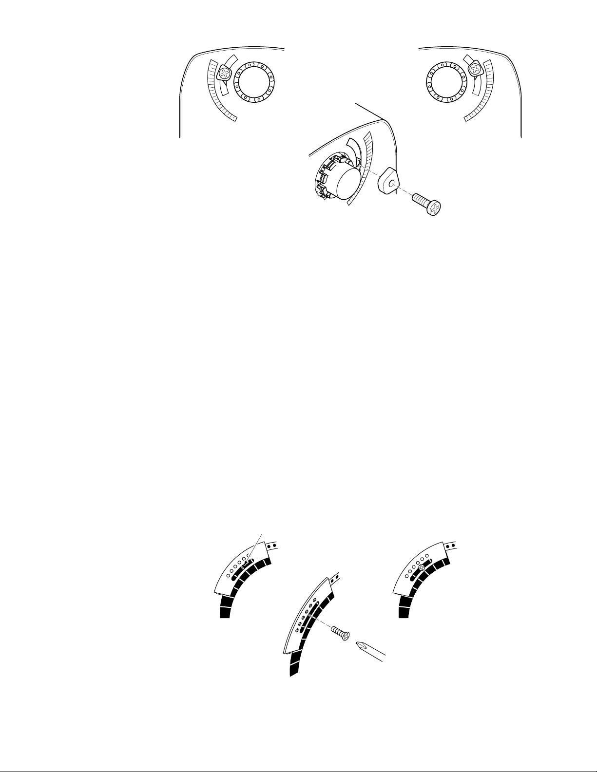
The AM-689 rotat ion lim iter is used in c onj uncti on with the t ab on the u niv ersal c lamp or t he
AM-686 position indicator which comes with the AM-689. In order to function properly, the
clamp or indicator must be mounted correctly.
The AM-689 rotation limiter controls the rotational output of the MA4X-715X, MA4X-715X502, MA4X-707X, and MA 4X-707X-502 ac tuators. It is used in app lications whe re a damper
has a designed rotation that is less than 90°, for exampl e with a 45° or 60° rotating damper.
1. Det ermine the amou nt of damper rotation required.
2. Locat e the AM-689 rotation limiter on the actuator so that its edge lines up with the
degree graduati on on the actuator face which correspo nds with the required rotatio n.
See Figure-6.
3. Find the appropriate cross-hai r l ocation through the slot of the rot ation limiter. This is
the mounting loca tion for the retaining screw.
4. Pierce thr ough the label material to all ow easy fastening of the retainin g screw.
5. Positi on the rot ation l imiter back to th e desired position, mak ing su re the lo cating “ teeth”
on the rotation li m it er are engaged into the locating holes on the actuator.
6. Fasten the rotation limiter to the actuator using the self-tapping screw provided.
7. Test the dam per rotation by applying powe r. Re-adjust if necessary.
Screw secured at
these cross hairs.
90
80
70
60
50
40
30
90
80
70
60
50
40
30
Angle of rotation
is now set at 40.
80
70
60
50
40
30
90
Figure-6 Securing the AM-689 Rotation Limiter.
20 © Copyright 2008 TAC All Rights Reserved. F-26642-7
Page 21

CHECKOUT
After the entire system has been installed and the actuator has been powered up, the
following check can be ma de for prope r system oper ation. Check for correct operation o f the
damper while actua tor is being stroked.
1. Apply power to the actuator. Actuator and damper should be driven to their powered
position.
2. On the MA4X-7XXX-50X mo dels, check for correct auxil iary switch operation.
3. Break power to the actuator. Actuator and damper should return to their normal, or
spring return position.
Table-5 Power Wiring Color Code.
Part Number L1 L2
MA4X-7XX3
MA4X-7XX3-502
MA4X-7XX0
MA4X-7XXX-502
MA4X-7XX1
MA4X-7XXX-502
Red Black
Black White
Brown Light Blue
THEORY OF
OPERATION
The actuators are mounted directly onto a damper shaft using a universal V-clamp. When
power is applied, the actuator rotates 95 ° to its powered position, at the same time tensing
the spring return saf ety mechanism. When power is remove d, the spring returns the actuator
to its normal position. The actuators provide true mechanical spring return operation for
reliable, positive close-off on air tight dampers.
The MA4X-707X, MA4X-707X-502, MA4X-715X, and MA4X-715X-502 actuators are
equipped with a graduated position indicator showing -5° to 90°. The MA40-704X and
MA40-704X-501 are equipped with a graduated position indicator showing 0 to 1.
The MA40-704X-501 m odels are provided wi th 1 built in auxili ary switch. The SPDT switch
is provided for int erfacing or signaling, for example, fan start-up. The switching function is
adjustable between 0° to 95° rotation (0 to 1 scale).
The MA4X-715X-502 and MA4X-707X-502 models are provided with 2 built in auxiliary
switches. The SPDT switches are provided for interfacing or signaling, for example, fan
start-up. The s wit ching functi on is adjust able on o ne swi tch bet ween 25° to 85° r ot ation and
the other switch is fixed at 5°.
The MA41-707X-XXX an d MA41- 715X- XXX actu ators are equi pp ed with a man ual ov errid e
mechanism. This al lows the actuator to be manually pos itioned at any point between -5o and
85o. This mechan is m is acces si ble on bo th sid es of the ac tuator and can be used to ensure
tight close- offs for valves and d ampers. The m anual overri de should not be used whil e a unit
is powered or on units that are mounted in tandem.
MAINTENANCE Regular maintenance of the total system is recomm ended to assure sustained opti m um
performance. The actuators are maintenance free.
FIELD REPAIR None. Replace with a functional actuator.
F-26642-7 © Copyright 2008 TAC All Rights Reserved. 21
Page 22
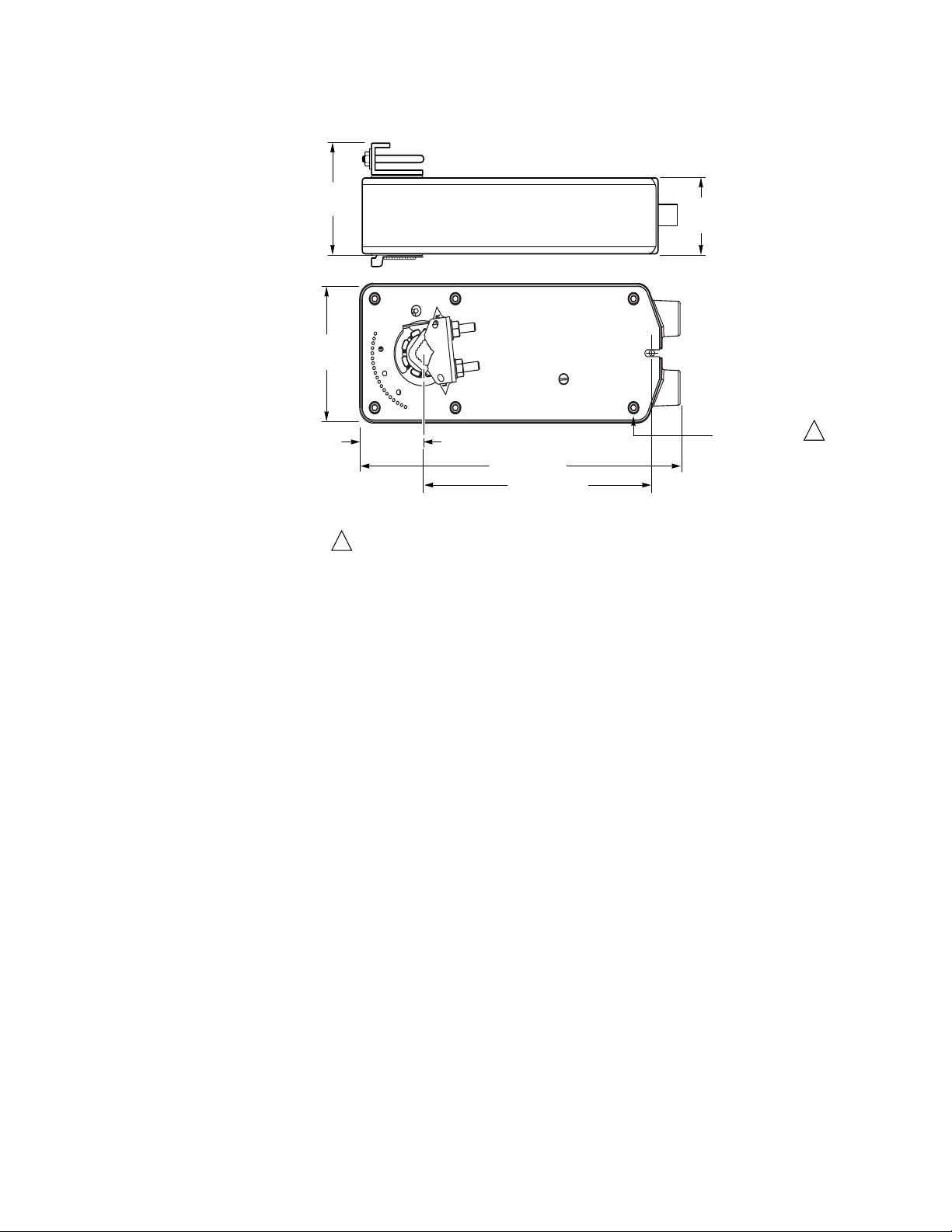
DIMENSIONAL DATA
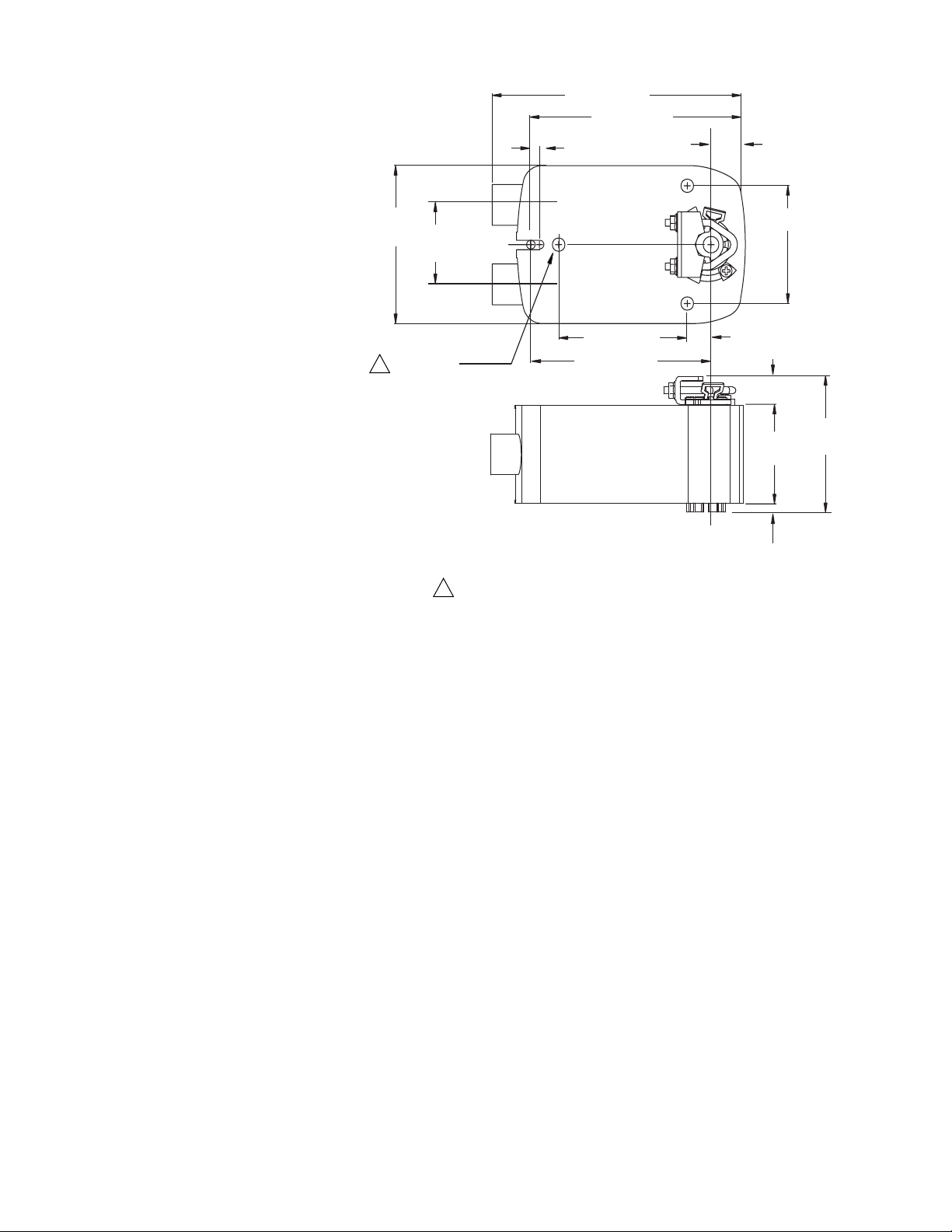
Figure-7 and Figu re- 8 dimensions are in inches (mm).
3-1/2
(89)
4
(103)
2-7/64
(53)
1
Note: These are not through holes. Use hardware supplied in
TAC approved AM kits.
Figure-7 MA4X-707X or MA4X-715X S eri es M ounting Dimensions.
10-1/2 (267)
7-1/2 (191)
2-25/64
(61)
6 Holes for
#10-24 Screws
Dimensions shown
are in inches (mm).
1
22 © Copyright 2008 TAC All Rights Reserved. F-26642-7
Page 23
s
6-51/64 (172)
6-13/64 (157)
13/32 (10)
1
(25)
4
(103)
1
2
(50)
3 Holes for
#10-24 Screws
Dimensions shown
are in inches (mm).
3-21/32 (93)
4-57/64 (125)
1
Note: These are not through holes. Use hardware supplied in
TAC approved AM kits.
47/64 (19)
49/64 (19)
1/4 (6.4)
Figure-8 MA40-704X Series Mounting Dimensions.
3-5/32 (80)
2-13/32
(61)
3-1/2 (62)
F-26642-7 © Copyright 2008 TAC All Rights Reserved. 23
Page 24

Copyright 2008, TAC
All brand names, trademarks and registered
trademarks are the property of their respective
owners. Information contained within this
document is subject to change without notice.
F-26642-7
TAC
1354 Clifford Avenue
P.O. Box 2940
Loves Park, IL 61132-2940
www.tac.com
 Loading...