

Page 1
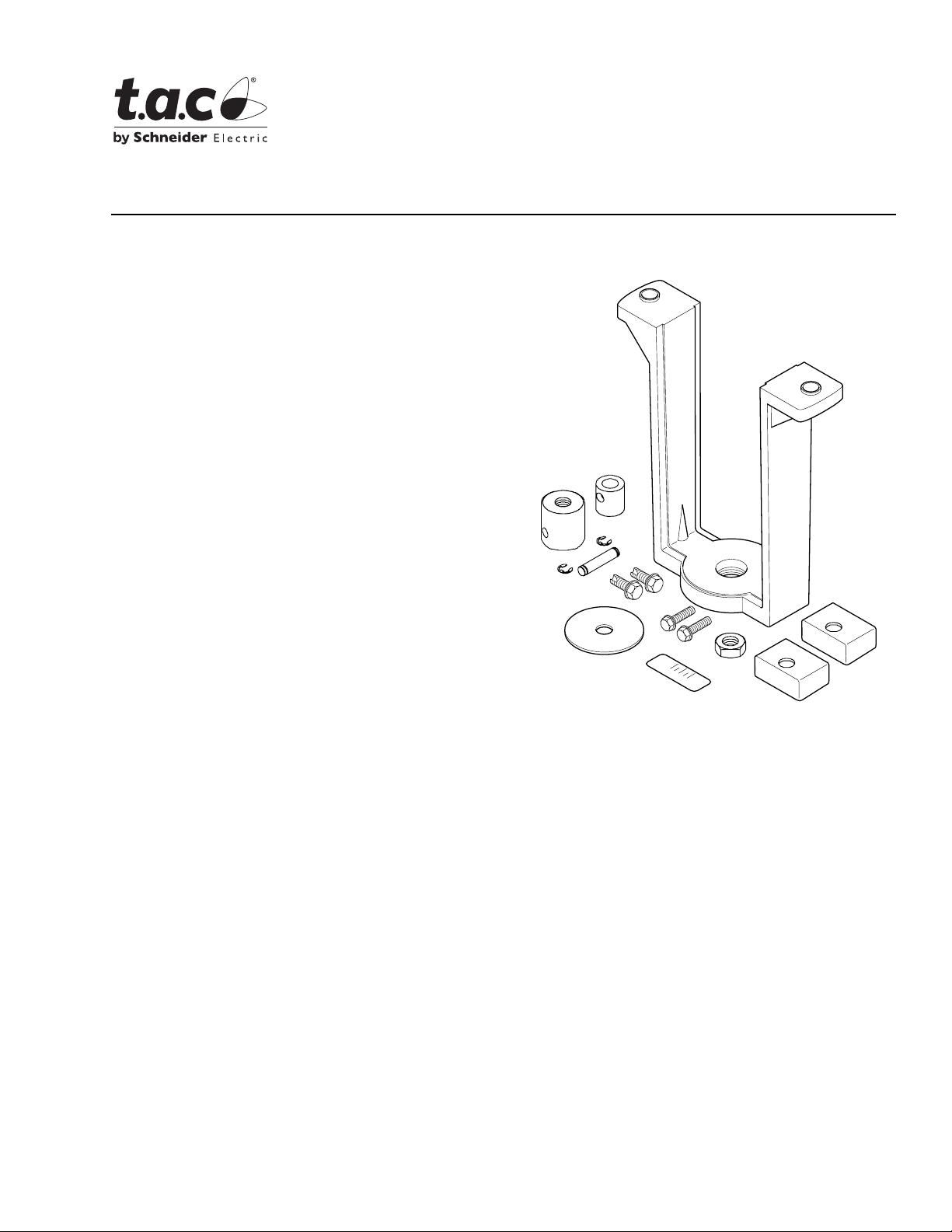
Application
The AV-496 valve linkage kit is used to field assemble
MK-88XX and MK-89XX series actuators to 2½ inch
through 6 inch VB-9XXX series valve bodies, except
VB-9323.
Features
AV-496
Valve Linkage for MK-88XX
and MK-89XX Actuators
General Instructions
• Die cast aluminum mounting bracket.
• Valve position indication provided as standard.
Applicable Literature
• TAC Cross-Reference Guide, F-23638
• TAC Reference Manual,
F-21683
• TAC Application Manual,
F-21335
• TAC Pneumatic Products Catalog, F-27383
• AK-42309-500 Positive Positioner Pneumatic Relay
General Instructions, F-22909
• EN-205 Water System Guidelines, F-26080
C
LOSED
C
LOSED
O
PEN
OPEN
Printed in U.S.A. 9-08 © Copyright 2008 TAC All Rights Reserved. F-21663-4
Page 2

SPECIFICATIONS
Table-1 AV-496 Valve Linkage Component Selection.
Valve Body
2-1/2 to 4”
VB-9XXX
5 & 6”
VB-9XXX
a
Except VB-9323 series valves.
a
Actuator Lock Nut Spacers Stem Adapters
MK-88XX 1/2” —
MK-89XX 1/2” 2
2 for
1/2” stem
2 for
1/2” stem
Stem
Link
Shaft
E-rings
12
12
Mounting
Bracket Bolts
2
1-1/4” long
2
2-1/4” long
Indicating
Plate
1 with
1/2” hole
1 with
1/2” hole
Scale
Length
1”
(25.4mm)
2”
(50.8mm)
INSTALLATION
Inspection Inspect the pack age for damage. If damaged, noti fy the appropriate carrier immediately . If
undamaged, open the package and inspect the device for obvious damage. Retu rn any
damaged products.
Requirements • Tools:
– Open end wrench, 3/4 inch
– Slotted screw driver
– Scale for measurin g the gap between valve stem and actuator shaft
• Training: Installer must be a qualifi ed, experienced technician
Caution:
• Avoid locations where excessive moisture, corrosive fum es, or vibration is present.
• Install all two-way valves so that t hey close agai nst the f low. An arrow on the valve bo dy
or a tag indicates the proper flow directi on.
• Always install three-way mixing valves with two inlets and one outlet.
• Do not install the actuator below the center line of the valve. For steam applications
mount the actuator above the valve body at 45° from vert ical.
2 © Copyright 2008 TAC All Rights Reserved. F-21663-4
Page 3

Linkage Kit
Installation
Two-way Normally Open VB-9213 2½ ” throu gh 6” Valve Bodies
Warning:
nut removed and repla ced [replace packing nut — tighten four (4) turns] along with the
bracket nut. Before removing packing nut, isolate the valve body using shutoff valves or
depressuriz e syst em to zero gau ge an d dr ain pi ping. System p ress ure cou ld cause pac ki ng
parts to blow out with potential of bodily injury and/or water damage.
1. Push the valve stem completely down.
2. Remove bracket nut from valve body. Refer to Figure-1.
3. Place mounting bracket onto valve body and secure it in place with the br acket nut.
4. Thread the stem lock nut all the way down the valve stem.
5. Place the indic ator plate on the valve stem .
6. Install an E-ring on one end of stem link shaft (pin). Insert the pin th rough the holes of
7. Thread t he val ve ste m adap ter on to the v alv e stem unt il the st em t ouches t he pin. Back
8. Secure the valve st em adapter, the AK-42309-500 spring arm (if requir ed), and the
Note:
AK-42309-500, Positive Positioner Pneumatic Relay General Instructions, F-22909,
for details.
2½” through 6” valve bodies date coded before 8603 must have valve packing
the valve stem adapt er.
the adapter off ½ turn (counterclockwise) and remove the pin.
indicator plate into place with the ste m lock nut. Refer to Figure-1.
For actuator/valve assemblies that require a positive positioner, refer to
9. Select the actuator (MK-88XX or MK-89XX series). For actuators details refer to
MK-8800 Series, MK-8900 Series, Pneumatic Valve Act uators General
Instructio ns, F-21662.
10. Thread actuator shaft adapter onto the actuator shaft as far as it will turn. Refer to
Table-1 for requir ed AV-496 components.
11. Usi ng the ap pro priat e bolts attach the sel ected act uat or to t he mounti ng bracke t. Refer
to Table-1. If MK-89XX ser ies actuator i s selected, install the spacers before attaching
the actuator to the bracket. Refer to Figure-1.
12. Turn actuator shaft adapter (countercl ockwise) until the distance between the surface
of the two adapte rs is 1. 100” (f or 5” and 6” valves with 2” s troke) or 0.100 ” (for 2-1/2” to
4” valves with 1” str oke). Use a scale or caliper to measure the distance.
13. Raise the valve stem to sl ide the valve stem adapter i nto the actuator shaft adapter.
14. Align the holes on both sides of the adapter assembly.
15. Insert the stem link shaft (pin) through the holes and place the second E-r ing on the
other end to secure the assembly.
16. Al ign t he top in dication mark er of the OPEN/CLOSE decal wit h the i ndicat or pl ate. Affi x
the OPEN/CLOSE decal to the mount ing bracket. Refer to Figure-1.
17. Li nkage assembly is compl ete. Refer to Figure-2 and Figure-3.
F-21663-4 © Copyright 2008 TAC All Rights Reserved. 3
Page 4
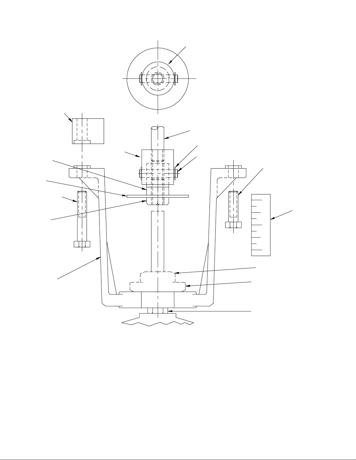
Spacer (2) for
MK-89XX Series
Actuators Only
Vertical View of
Actuator Shaft Adapter
Actuator Piston*
Stem
Valve
Stem
Adaptor
Indicator
Plate
Mounting Bolt (2)
for MK-8900 Series
Stem
Lock Nut
Mounting
Bracket
Actuator Shaft
Adapter
E-Ring (2)
Stem Link Shaft
Mounting Bolt (2)
for MK-8800 Series
OPEN
CLOSED
*Packing Nut
*Bracket Nut
*Valve Body
OPEN
CLOSED
Decal
*Not Included with AV-496.
Figure-1 AV-496 Valve Linkage Ki t Components.
4 © Copyright 2008 TAC All Rights Reserved. F-21663-4
Page 5

Linkage Kit
Installation
(Continued)
Two-way Normally Closed VB-9223 2½” thro ugh 6” and
Three-way Mixing VB-9313 2½” through 6” Valves Bo dies
Warning:
nut removed and repla ced [replace packing nut — tighten four (4) turns] along with the
bracket nut. Before removing packing nut, isolate the valve body using shutoff valves or
depressuriz e syst em to zero gau ge an d dr ain pi ping. System p ress ure cou ld cause pac ki ng
parts to blow out with potential of bodily injury and/or water damage.
1. Push the stem completely down.
2. Remove the bracket nut from valve body. Refer to Figure-1.
3. Place the m ounting bracket onto the v alve body and secure it in place with the bracket
4. Thread the stem lock nut all the way down the valve stem.
5. Place the indic ator plate on the valve stem .
6. Install an E- ri ng on one end of the stem link shaft (pin). Insert the pin t hrough the hole
7. Thread t he val ve ste m adap ter on to the v alv e stem unt il the st em touch es t he pin. Back
8. Secure the valve st em adapter, the AK-42309-500 spring arm (if requir ed), and the
Note:
AK-42309-500, Positive Positioner Pneumatic Relay General Instructions, F-22909,
for details.
2½” through 6” valve bodies date coded before 8603 must have valve packing
nut.
on the valve stem adapt er.
the adapter off ½ turn (counterclockwise) and remove the pin.
indicator plate into place with the ste m lock nut. Refer to Figure-1.
For actuator/valve assemblies that require a positive positioner, refer to
9. Select the actuator (MK-88XX or MK-89XX series). For actuators details refer to
MK-8800 Series, MK-8900 Series, Pneumatic Valve Act uators General
Instructio ns, F-21662.
10. Thread the actuator shaft adapter onto the actuator stem as far as it will turn. Refer to
Table-1 for requir ed AV-496 components.
11. Usi ng the ap pro priat e bolts attach the sel ected act uat or to t he mounti ng bracke t. Refer
to Table-1. If MK-89XX series actuator is selected install the spacers before attac hing
the actuator to the bracket. Refer to Figure-1.
12. Raise the valve stem completely up, so that the disc rest against the top seat.
13. Turn the actuator shaf t adapter countercl ockwise until the holes on the adapters are
aligned.
14. Screw the actuator shaf t adapter 1½ turns furth er cl ockwise onto the actuator shaft.
15. Apply air pressure to actuator until the holes on the adapters are aligned.
16. Insert the stem link shaft (pin) through the holes and place the second E-r ing on the
other end to secure the assembly.
17. Release pressure to act uator and allow valve assembl y to spring return to the cl osed
position.
18. Al ign t he top in dication mark er of the OPEN/CLOSE decal wit h the i ndicat or pl ate. Affi x
the OPEN/CLOSE decal to the mount ing bracket. Refer to Figure-1.
19. Li nkage assembly is compl ete. Refer to Figure-2 and Figure-3.
MAINTENANCE The actuator linkage requires no maintenance. Regular maintenance of the total system is
recommended to assure sustained optimum performance. Hard water leaves abrasive
deposits and reduces component life. To maximize valve life, consult EN-205 Water
System Guidelines, F-26080.
F-21663-4 © Copyright 2008 TAC All Rights Reserved. 5
Page 6
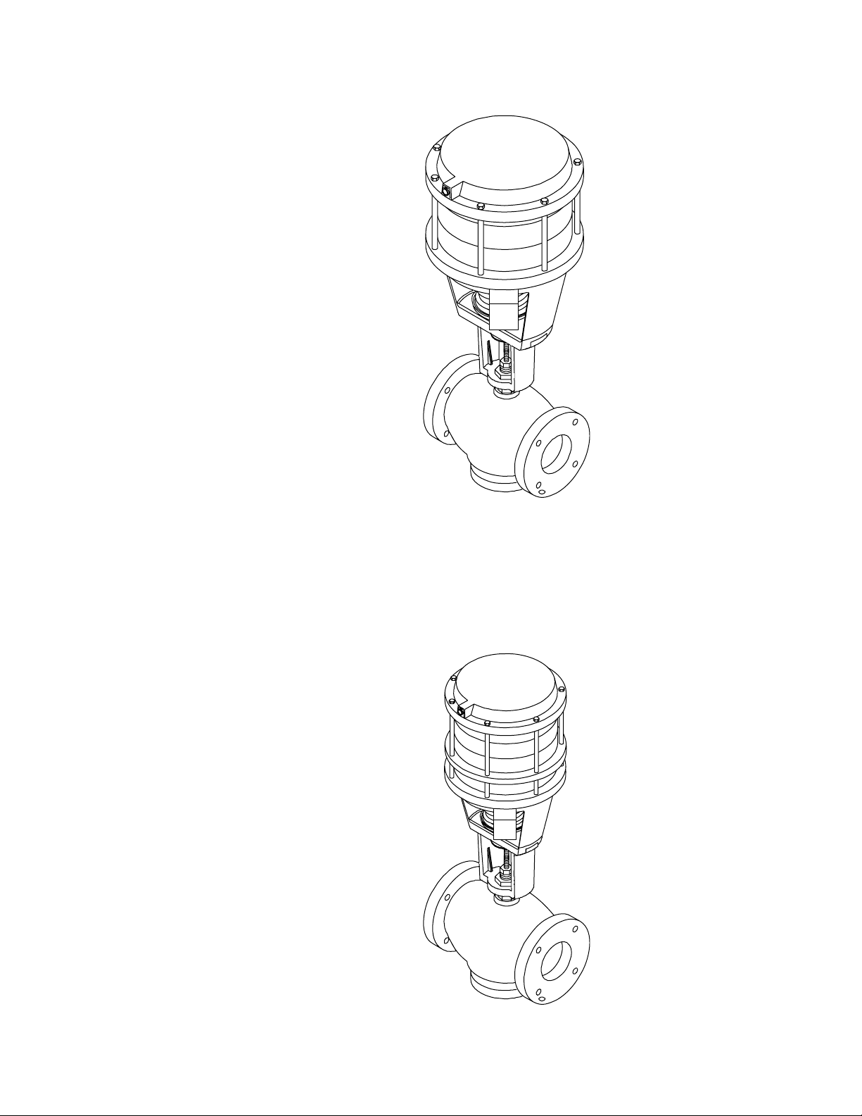
Figure-2 MK-8800 Series Actuator Valve Assembly.
Figure-3 MK-8900 Series Actuator Valve Assembly.
6 © Copyright 2008 TAC All Rights Reserved. F-21663-4
Page 7

F-21663-4 © Copyright 2008 TAC All Rights Reserved. 7
Page 8

Copyright 2008, TAC
All brand names, trademarks and registered
trademarks are the property of their respective
owners. Information contained within this
document is subject to change without notice.
F-21663-4
TAC
1354 Clifford Avenue
P.O. Box 2940
Loves Park, IL 61132-2940
www.tac.com
 Loading...