

Page 1
TAC
1354 Clifford Avenue
P. O. Box 2940
Loves Park, IL 61132-2940
www.tac.com
Application
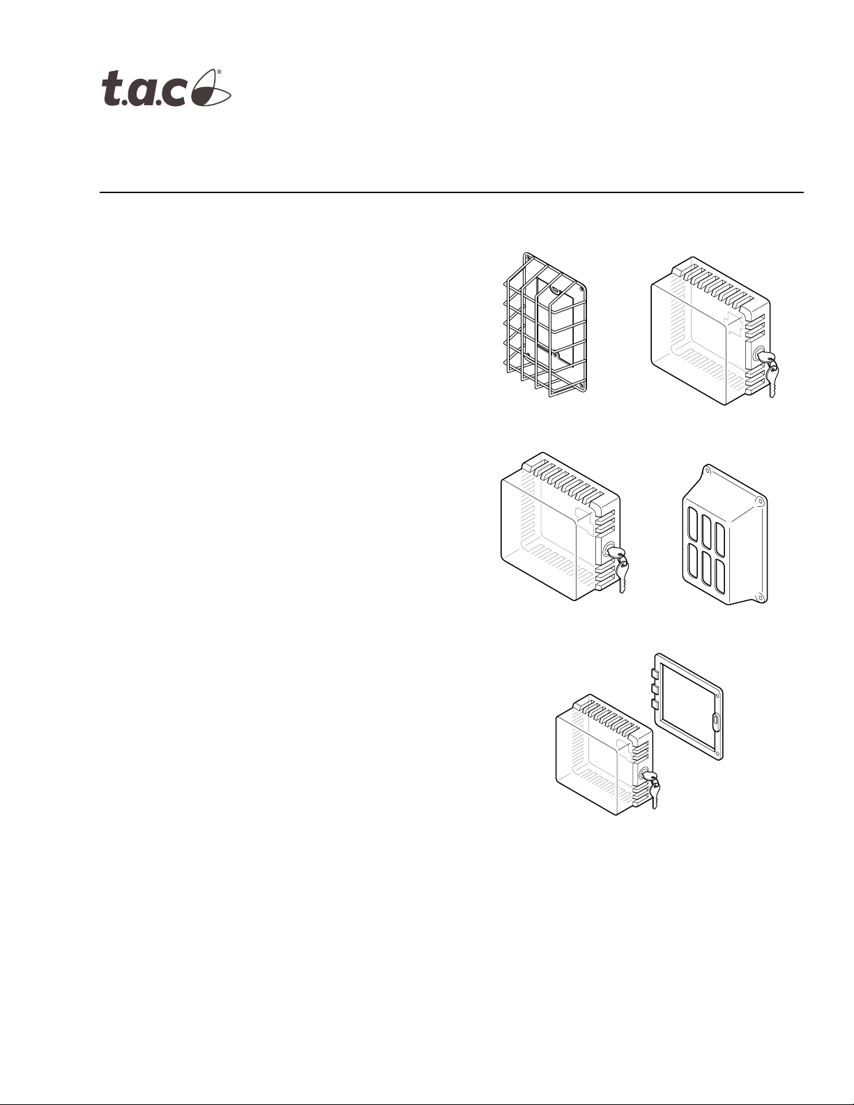
Room thermostat guards protect thermostats from
damage and vandalism.
Features
• Available in plastic, cast aluminum, or wire
construction.
• Outlet or direct wall mounting.
AT-1103
AT-1163
AT-1100 Series
Thermostat Guards
General Instructions
AT-1105
• Tumbler type key lock available on some models.
• Mounting ring available for installing guard without
removing thermostat from the wall.
Applicable Literature
• AT-546 Auxiliary Mounting Base General
Instructions, F-15658
• AT-602, 603, 607, 608, and 609-XXX Selector
Switch Sub-bases and Legend Plates General
Instructions, F-16059
• TAC Reference Manual, F-21683
• TAC Cross Reference Guide, F-23638
• TAC Pneumatic Produccts Catalog, F-27383
AT-1155
AT-1104
AT-1165
AT-1105
Printed in U.S.A. 9-06 © Copyright 2006 TAC All Rights Reserved. F-07930-13
Page 2
SPECIFICATIONS
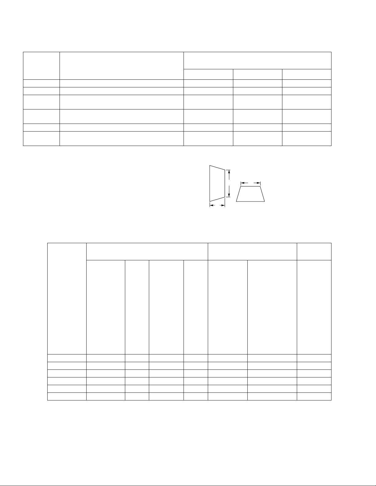
Table-1 Thermostat Guard Dimensions.
TAC
Model No.
AT-1103 Wire Guard with Steel Base Plate 4-1/4 (108) 2-5/8 (67) 1-5/8 (41)
AT-1104 Cast Aluminum Guard with Steel Base Plate 4-1/4 (108) 3-1/2 (89) 1-5/8 (41)
AT-1105
AT-1155
AT-1163 Wire Guard with Steel Base Plate 6-1/2 (165) 6-5/8 (168) 3-1/4 (83)
AT-1165
Clear Plastic Guard with Solid Base
Clear Plastic Guard with Solid & Ring Base
Clear Plastic Guard with Solid & Ring Base
Description
and Tumbler Type Key Lock
and Tumbler Type Key Lock
and Tumbler Type Key Lock
HWD
3-7/8 (98) 3-1/2 (89) 2-1/2 (63)
6-1/4 (159) 5-1/2 (140) 3-1/4 (83)
8 (203) 5-1/2 (140) 3-1/2 (89)
Inside Dimensions in. (mm)
H
W
D
Side View End View
Figure-1 Dimensions.
Table-2 Thermostat and Guard Compatibility.
Single Thermostat
TAC
Model No.
(x indicates
thermostat
guard
compatibility
with listed
devices)
AT-1103 x x x
AT-1104 x x x x
AT-1105 x x x x
AT-1155 x*
AT-1163 x†
AT-1165 x* x x x x* x*
*Can be installed with or without AT sub-bases.
†Requires an AT-504 or AT-600 series sub-base.
‡AT-1163 will accept two single stats on an AT-546 auxiliary mounting base.
** Requires an AT-504 a uxiliary mounting ba se (except TA-135).
TA-1101
TA-1102
TA-1501
TF-1111
TC-1100 Series
TP-1011
TP-1031
‡
TA-121
TA-135
TC-114
x**
HKS-5033
TK-1XXX
TK-5XXX
TKR-1XXX
TKR-5XXX
TKS-5001
xx x* x x
x‡ x†‡ x x*
HC-101
Any 2x2
Wall
Mounted
Device
Single Humidity, Temperature,
or Sensing Element
HS-8101
HSP-824X
TP-8101
TP-8102
TP-8121
TP-8124
TP-8232
TS-5191
TS-5711
TS-5811
TS-8101
TS-811X
TS-8811
TSP-8X15X
HSP-814X
TS-57011 Series
TS-58001 Series
TS-81001 Series
TS-90110
TSMN-57011-850
TSMN-58011
TSMN-81011
TSP-8X251
Dual
Thermostat
TC-1151
TC-1161
ACCESSORIES
AT-546 Dual Mounting Base.
AT-600 Series Selector Switch Sub-bases and Legend Plates.
2 © Copyright 2006 TAC All Rights Reserved. F-07930-13
Page 3

INSTALLATION
Inspection
Requirements
Location
Mounting
Inspect the package for damage. If damaged, notify the appropriate carrier immediately.
If undamaged, open the package and inspect the device for obvious damage. Return damaged products.
•
Tools (not provided):
– Appropriate screwdriver, drill, and drill bit for mounting screws.
• Appropriate accessories.
• Mounting screws (not provided).
• Training: Installer must be a qualified, experienced technician.
C A U T I O N
Do not locate unit in areas subject to excessive moisture, corrosive fumes, or vibration.
NEMA Type 1 devices are intended for indoor use primarily to provide a degree of protection against contact with the enclosed equipment.
9
0
8
0
7
0
6
0
5
0
Mounting Bracket
Guard
Thermostat
Base Plate
Figure-2 Typical of AT-1103, AT-1104, and AT-1163.
N O T E
Make wiring connections to thermostat as required during installation.
AT-1103 Wire Guard & AT-1104 Aluminum Guard (Figure-2)
To mount thermostat with mounting bracket:
1. Using screws provided with thermostat, attach mounting bracket and base plate to switch
box.
2. Make required connections to thermostat and attach thermostat to mounting bracket.
3. Attach guard to base plate using the four Phillips head screws provided with the guard.
To mount thermostat without mounting bracket:
1. Make required connections to thermostat.
2. Using screws provided with thermostat, attach thermostat and base plate to switch box.
3. Attach guard to base plate using the four Phillips head screws provided with the guard.
AT-1163 Wire Thermostat Guard (Figure-2)
To mount thermostat without sub-base or auxiliary mounting base:
1. Using screws provided with thermostat, attach mounting bracket and base plate to switch
box.
2. Make required connections to thermostat and attach thermostat to mounting bracket.
3. Attach guard to base plate using the four Phillips head screws provided with the guard.
To mount thermostat with auxiliary mounting base or AT-546:
1. Attach thermostat bracket, auxiliary mounting base, and base plate to switch box as
required with screws provided.
2. Make required connections to thermostats.
3. Attach guard to base plate using the four Phillips head screws provided with the guard.
F-07930-13 © Copyright 2006 TAC All Rights Reserved. 3
Page 4
To mount thermostat with AT-600 Series sub-base:
1. Using screws provided with device, attach AT-600 Series sub-base and base plate to
switch box.
2. Make required connections to sub-base.
3. Attach thermostat mounting bracket as required and make required connections to thermostat.
4. Using screws provided, attach thermostat to sub-base or mounting bracket on
sub-base.
5. Attach guard to base plate using the four Phillips head screws provided with the guard.
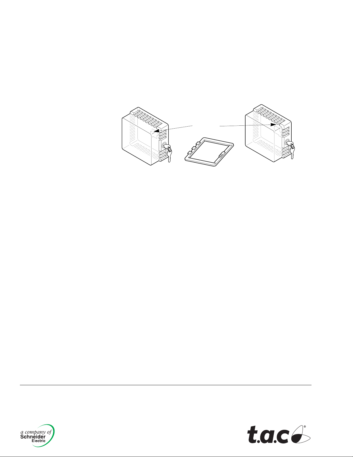
AT-1105, AT-1155, or AT-1165 Plastic Thermostat Guards (Figure-3)
Solid Base
AT-1105
Ring Base
AT-1155
AT-1165
Figure-3 Typical of AT-1105, AT-1155, and AT-1165.
To mount guard and thermostat with solid base:
1. Remove thermostat guard cover from the base and put base down with paper template
side up.
2. Center the thermostat (or sub-base) and align at least two thermostat (or sub-base)
mounting holes with corresponding holes on the template and mark holes with a pencil.
3. If possible, use the same screws to attach both the guard base and thermostat (or
sub-base) to the wall or to an outlet box.
4. If the guard and thermostat must mount separately, make the holes for the thermostat
and use the self-tapping screws.
5. Select two other holes for mounting the guard to the wall.
6. Punch out the holes as marked on the template, making the holes large enough for the
preselected screws.
7. Pull enough wire from the wall to make connection to the thermostat or sub-base. Pull
wire through opening in the guard sub-base.
8. If necessary, connect wires to thermostat before mounting thermostat and guard base.
9. Mount thermostat and guard base to wall or outlet box.
10. Attach wires to thermostat, mount the thermostat to guard base, and lock the thermostat
guard cover onto the base.
To mount ring base (AT-1155 and AT-1165 only):
1. Place the ring base around mounted thermostat and center thermostat in the opening.
2. Mark mounting holes, making sure ring base is parallel to thermostat.
3. Using mounting screws provided, mount the ring base to the wall and lock cover onto
base.
Copyright 2006, TAC
All brand names, trad emarks and registered
trademarks are the property of their respective
owners. Information contained within this
document is subject to change without notice.
F-07930-13
TAC
1354 Clifford Avenue
P.O. Box 2940
Loves Park, IL 61132-2940
www.tac.com
 Loading...