

Page 1
TAC
1354 Clifford Avenue
P. O. Box 2940
Loves Park, IL 61132-2940
www.tac.com
APPLICATION
For applications where an electrical circuit is used to
control a pneumatically-operated device. Used to direct
supply air to a pneumatic device when the coil is
energized or de-energized, depending on the supply
and exhaust air connects.
FEATURES
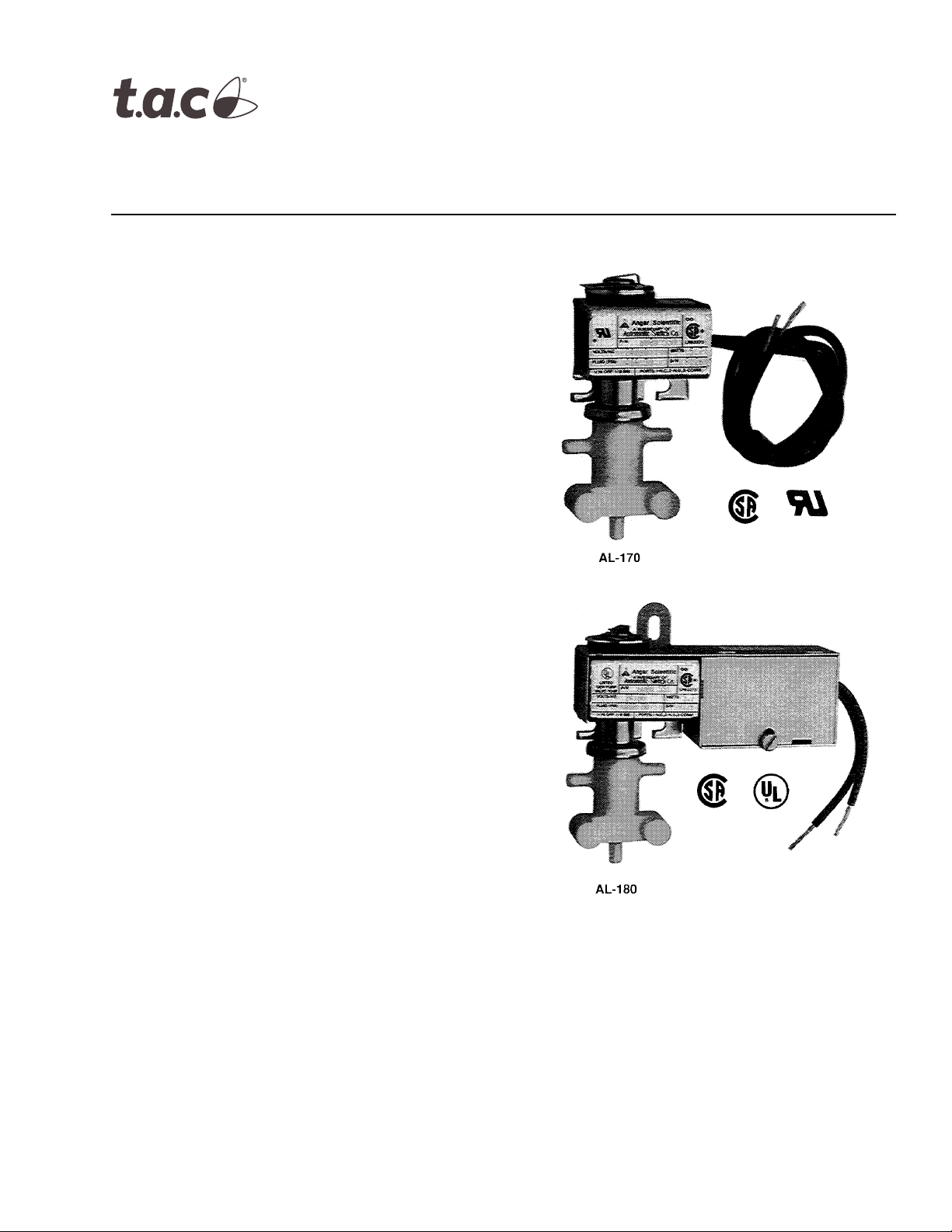
• Open frame or junction box construction
accommodates a wide variety of NEMA 1 mounting
locations.
AL-170 Series
AL-180 Series
Solenoid Air Valves
General Instructions
• Available in 24, 120, 208, 240, or 480 Vac models.
• Supplied with 18" electrical leads for ease of
installation.
• Corrosion-resistant plastic body.
• Barbed fittings for 1/4" O.D. plastic tubing.
APPLICABLE LITERATURE
• TAC Cross-Reference Guide F-23638
• TAC Reference Manual F-21683
• TAC Application Manual F-21335
• EN-123 Air Quality Requirements for Pneumatic
HVAC Control Systems F-22516
Printed in U.S.A. 11-06 © Copyright 2006 TAC All Rights Reserved. F-24748-1
Page 2
SPECIFICATIONS
Valve Inputs Power Input: 6.5 Watts (energized).
Voltage: For available voltages, see Table-1.
Electrical Connections: 18” (457 mm) leads on the coil.
Maximum Inlet Air Pressure: 30 psig (207 kPa). Clean, dry, oil free air is required
(reference EN-123).
Air Connections: Three plastic ferrules included for plastic 1/4" tubing (PKG-1141).
N.C., Normally closed, port 1.
N.O., Normally open, port 2.
COM, Common, port 3.
Valve Outputs Flow Capacity: 0.3 scfm (142 ml/s) at 15 psig (103 kPa) supply with 1 psig (6.9 kPa) drop.
Environment Ambient Temperature Limits:
Shipping, -40 to 150°F (-40 to 65°C).
Operating, 40 to 130°F (4 to 54°C).
Supply Air, 40 to 130°F (4 to 54°C).
Humidity: 5 to 95% RH, non-condensing.
Location: NEMA Type 1.
Mounting: Vertical with solenoid at top (as shown).
TYPICAL APPLICATIONS
Solenoid
Open Frame J-Box
AL-170 AL-180 24 PNR-325-24
AL-171 AL-181 120 PNR-325-120
N/A AL-182 208 PNR-325-208
N/A AL-183 240 PNR-325-240
N/A AL-185 480 PNR-325-480
ACCESSORIES None
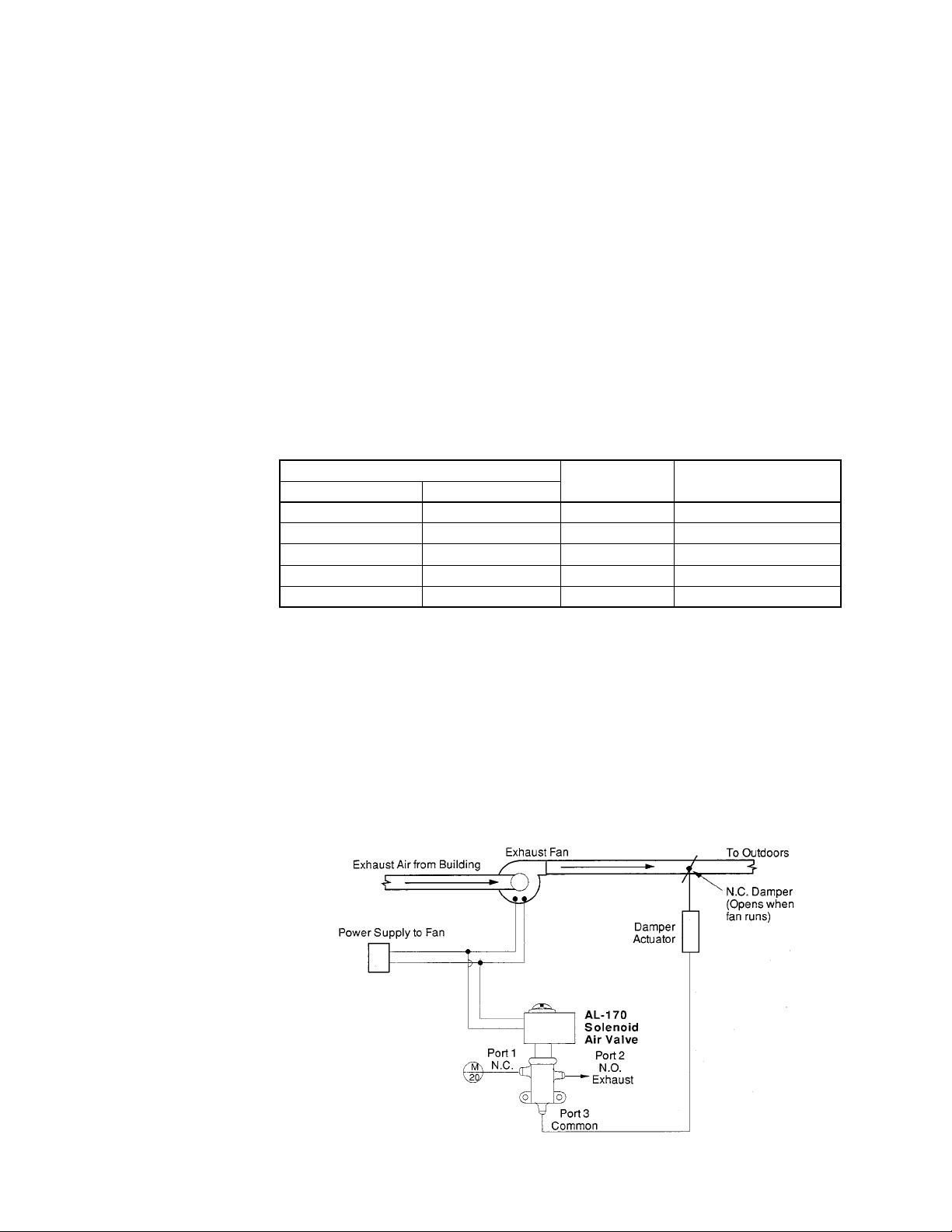
When power is supplied to the exhaust fan, the fan runs, and the solenoid air valve is
energized, closing port 2 and passing main air from port 1 through port 3 to damper actuator,
which opens the normally-closed exhaust damper.
When power is removed from the fan, the fan stops, and the solenoid air valve is deenergized, closing port 1 and bleeding air from the damper actuator through port 3 and out
port 2 to atmosphere, closing the exhaust damper.
Figure 1 illustrates a typical application diagram for the AL-170 solenoid air valve.
Voltage
(AC 60 Hz)
TAC Replacement Part
Numbers
Figure-1 Typical Application Diagram.
2 © Copyright 2006 TAC All Rights Reserved. F-24748-1
Page 3
INSTALLATION
Inspection
Inspect the carton for damage. If damaged, notify the appropriate carrier immediately.
Inspect the device for obvious damage. Return damaged products.
Requirements
• Job wiring diagrams
• Tools (not provided)
• Training:
Installer must be a qualified experienced technician.
Warning:
shock and equipment damage.
Caution:
with national and local electrical codes.
Do not exceed ratings of the devices.
Avoid locations where excessive moisture, corrosive fumes, or vibration is present.
Disconnect the power supply (line power) before installation to prevent electrical
Make all connections in accordance with the wiring diagram and in accordance
Mounting Remote Mounting
Warning:
plate is provided.
1. Fasten to wall or duct with two #8 sheet metal screws or equivalent.
2. Rotate the solenoid enclosure to position the wiring compartment, if necessary.
Warning:
This method requires the use of the enclosure on the coil. An integral mounting
Do not over-tighten as this may cause distortion of plunger tube or damage coil.
CHECKOUT
Go, No Go Test
1. Connect solenoid ports to plastic tubing.
2. Apply air to port 3. Ports 3 and 2 should be connected.
3. Apply power to the solenoid. Ports 3 and 1 should be connected.
4. If ports 3 and 1 are not connected, check to see if the proper voltage is applied.
5. Replace the solenoid with a functional unit if solenoid is powered and ports 3 and 1 are
not connected.
Use copper conductors only.
MAINTENANCE
Regular maintenance of the total system is recommended to assure sustained optimum
performance.
FIELD REPAIR
None. Replace with a functional solenoid.
F-24748-1 © Copyright 2006 TAC All Rights Reserved. 3
Page 4
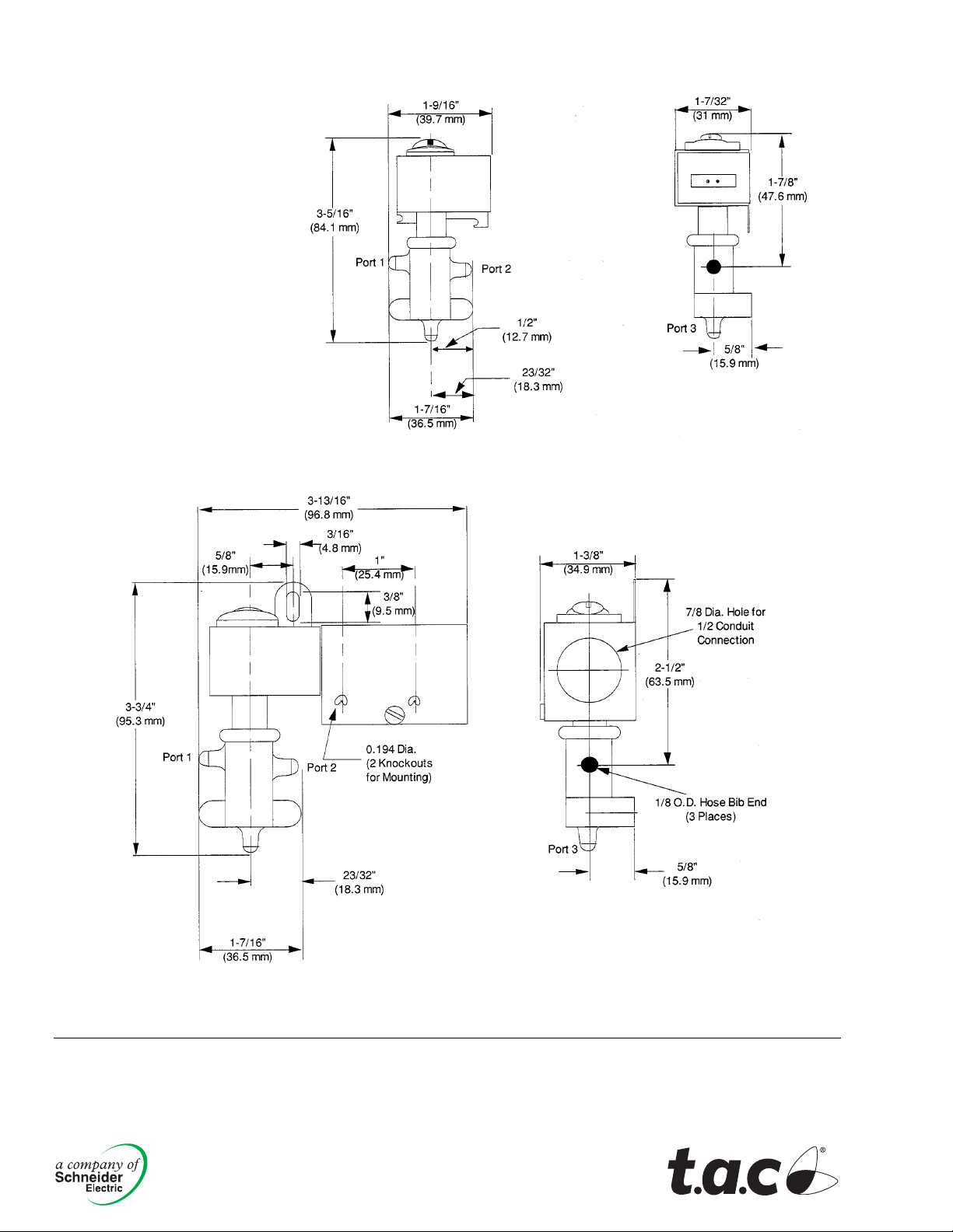
DIMENSIONAL DATA
Figure-2 AL-170 Dimensional Drawing.
Copyright 2006, TAC
All brand names, trad emarks and registered
trademarks are the property of their respective
owners. Information contained within this
document is subject to change without notice.
F-24748-1
Figure-3 AL-180 Dimensional Drawing.
TAC
1354 Clifford Avenue
P.O. Box 2940
Loves Park, IL 61132-2940
www.tac.com
 Loading...