

Page 1

TAC
1354 Clifford Avenue
P. O. Box 2940
Loves Park, IL 61132-2940
www.tac.com
Application
The AL-161-4 is a three-way air switching valve used
for central supply air changeover in dual pressures
systems.
Features
• Die cast aluminum actuator with replaceable
neoprene diaphragm
AL-161-4
Three-way Air Switching Valve
General Instructions
Applicable Literature
• TAC Cross-Reference Guide, F-23638
• TAC Reference Manual, F-21683
• TAC Application Manual, F-21335
• TAC Valve Products Catalog, F-27384
• EN-123 Air Quality Requirements for Pneumatic
HVAC Control Systems, F-22516
Printed in U.S.A. 10-06 © Copyright 2006 TAC All Rights Reserved. F-21286-3
Page 2

SPECIFICATIONS
Valve Body Rating: 250 psig (1724 kPa).
Actuator Maximum Air Pressure: 30 psig (207 kPa).
Spring Range 8-13 psig (55-90 kPa).
Flow Capacity: 25,920 scim (7,080 ml/s) at 15 psig (103 kPa) supply with 1 psig (6.9 kPa)
drop.
Connections:
Actuator, 1/8" FNPT.
Valve Body, 1/2" FNPT.
Port Code and Flow Pattern: See Table-1.
Ambient Temperature Limits:
Shipping & Storage, -40 to 220 ° F (-40 to 104° C).
Operating, 35 to 140° F (2 to 60° C).
Humidity: 5 to 95% RH, non-condensing.
Location: NEMA Type 1.
Table-1 Flow Pattern.
Stem Up
(No Air to Actuator)
Flow Closed Port Flow Closed Port
B to AB* A A to AB* B
*AB Common.
20 psig (138 kPa) Air to Actuator
Stem Down
2 © Copyright 2006 TAC All Rights Reserved. F-21286-3
Page 3
TYPICAL APPLICATIONS
INSTALLATION
Inspection
Requirements
Electric Time
L1
L2
1
AL-1XX
Switch
Contacts Open:
Contacts Closed:
Inspect the package for damage. If damaged, notify the appropriate carrier immediately.
If undamaged, open the package and inspect the device for obvious damage. Return
damaged products.
Solenoid Air Valve
1
(E/P Relay)
M
20 psig to Thermostats
15 psig to Thermostats
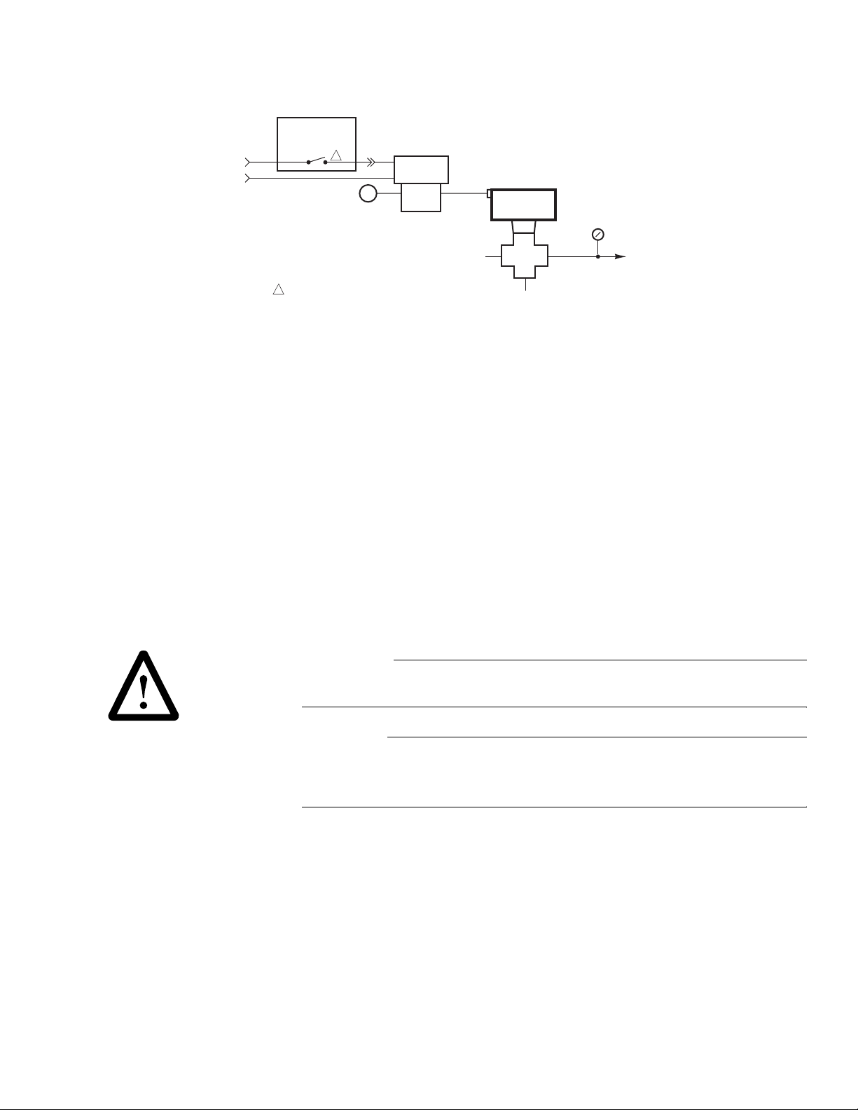
Figure-1 Typical Piping Diagram.
N.C.
N.O.
C
15 psi
(103 kPa)
AL-161-4
AAB
B
20 psi
(138 kPa)
Pressure
Gauge
0-30 psig
Supply Main to
Thermostats
• Job piping diagrams
• Tools (not provided):
– Appropriate drill and drill bit for mounting screws
– Appropriate screw drivers and wrenches
• Mounting screws (not provided)
• Training: Installer must be a qualified, experienced technician
W A R N I N G
• Disconnect the power supply (line power) before installation to prevent equipment damage.
• Make all connections in accordance with the piping diagram
C A U T I O N
.
• Do not exceed the ratings of the device(s).
• Avoid locations where excessive moisture, corrosive fumes, or vibration is present.
• Do not install insulation on any part of the actuator.
F-21286-3 © Copyright 2006 TAC All Rights Reserved. 3
Page 4
Mounting
Piping
CHECKOUT
MAINTENANCE
FIELD REPAIR
DIMENSIONAL DATA
The AL-161-4 is not position sensitive.
1. Mount the AL-161-4 to the wall or the subpanel of a control cabinet at any angle, using
the attached mounting bracket.
2. Use three (3) 1/4" (6 mm) mounting screws (not provided) to secure the AL-161-4 to the
mounting surface.
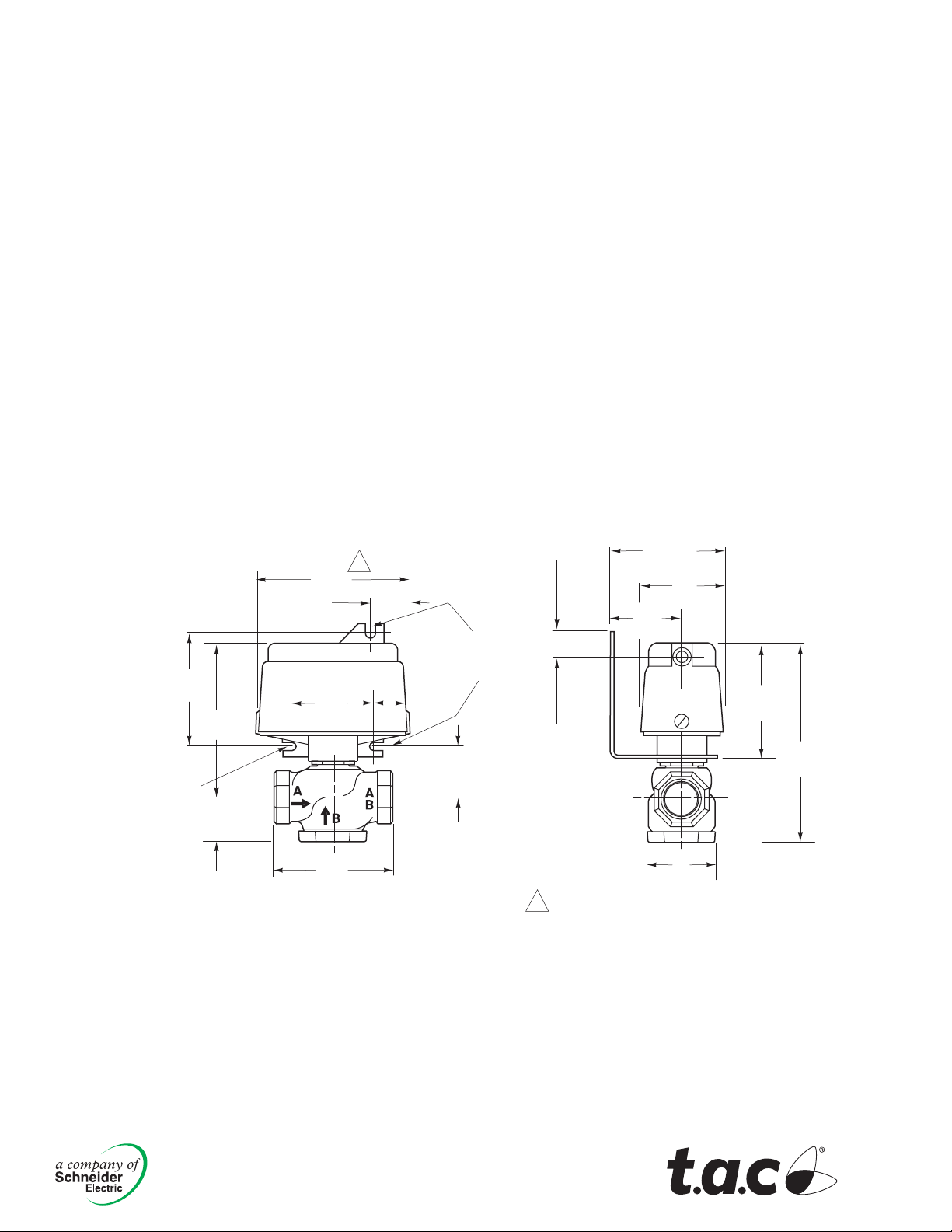
3. See Figure-2 for mounting dimensions.
Refer to the typical piping application in Figure-1.
With no air to the actuator the flow will be from ports B to AB. Apply 20 psig (38 kPa) to the
actuator; the flow will be from ports A to AB.
Regular maintenance of the total system is recommended for sustained optimum
performance. For information on air quality requirements consult EN-123, Air Quality
Requirements for Pneumatic HVAC Control Systems, F-22516.
Use part number PNV-102-1 when the replacement of the actuator diaphragm is necessary.
See Figure-2 for dimensional data.
3-1/2
(89)
Mounting Slot
9/32 (7) dia.
4-13/16
(122)
1-1/4
(32)
1
4-5/8
(117)
2-1/2
(64)
(76)
1-1/4
(32)
Mounting
Slots
1-1/8
(29)
3
9/32 (7) dia.
1-5/8
(41)
7/8 (22)
1
Allow 3" (76 mm) clearance above
assembly for actuator removal.
Dimensions in inches. ( ) mm.
Figure-2 AL-161-4 Air Switching Valve Dimensions.
2-13/16
(71)
2-1/4
(57)
1-11/16
(43)
3-5/8
(92)
6-1/16
(154)
1-15/32
(37)
Copyright 2006, TAC
All brand names, trad emarks and registered
trademarks are the property of their respective
owners. Information contained within this
document is subject to change without notice.
F-21286-3
TAC
1354 Clifford Avenue
P.O. Box 2940
Loves Park, IL 61132-2940
www.tac.com
 Loading...