

Page 1

TAC
1354 Clifford Avenue
P. O. Box 2940
Loves Park, IL 61132-2940
www.tac.com
Application
The 2218 Series Pneumatic Room Thermostats are
designed for proportional control of pneumatic valves
and damper actuators in environmental control
systems where a dual presure air main is utilized for
seasonal changeover of heating and cooling functions.
Their design incorporates a highly sensitive, bimetal,
thermostatic element, and a pilot-operated relay with
pneumatic feedback for accuracy and stability over the
entire operating range.
Indexing the thermostat from summer control (reverse
acting) to winter control (direct acting), or vice versa, is
accomplished by remotely changing the main air
pressure supply from 16 psig (summer) to 25 psig
(winter). Models are also available that operate on
slightly different pressures to replace many competitive
devices.
2218 Series
Summer-Winter
Pneumatic Room Thermostats
General Instructions
Full Dial Cover Shown
(Covers must be ordered
separately except as noted.)
These thermostats have a serrated thumb wheel for
setpoint adjustment. Models are also available with
preassembled internal dial stops. Thermostat covers
are available in various styles to meet particular
requirements. Cover options include models with a
setpoint scale and a thermometer, a setpoint scale
only, a thermometer only, or blank. An external setpoint
adjustment cover is available on some models, or can
be field-installed on covers where desired.
Features
• Factory-calibrated, stainless steel ball-in-seat
provides pneumatic feedback for stable, linear
operation.
• Snap-acting (not gradual) changeover from direct
action to reverse action operation and vice versa.
• Easy-to-use throttling range adjustment and
recalibration.
• Adjustable (patented) bimetal shows actual
throttling range in both °F and °C. Adjustable 2 to
12 °F (1 to 6.7 °C).
• Leak-proof, self-closing branch gauge tap.
SPECIFICATIONS
Action: Proportional.
Setpoint Range: See Table-1 and Table-2.
Throttling Range: See Table-1 and Table-2.
Supply Air Pressure:
Below 16 psig, Operates at summer setpoint.
Above 25 psig, Operates at winter setpoint.
Maximum Air Pressure: 30 psig.
Main Air Consumption: See Table-1 and Table-2.
Calibration Point: See Table-1 and Table-2.
Summer/Winter Indexing: Remote, by change in main air
pressure.
Setpoint Adjustment: Serrated thumbwheel.
Construction:
Mechanical Components, Die cast aluminum, stainless
steel, and glass-filled nylon.
Diaphragm, Fabric-reinforced Neoprene.
Air Lines, Connect to thermostat nipples with
spring-reinforced plastic tubes.
Branch Connections, Equipped with internal fiters.
Environment
Humidity: 5 to 95% relative humidity, non-condensing.
Locations: NEMA Type 1.
Printed in U.S.A. 08/06 © Copyright 2006 TAC All Rights Reserved. F-24579-2
Page 2

ORDERING DATA
Table-1 Model Chart — Thermostats.
Wholesale
Number
Replaces
Model
Action
Setpoint
Range
Calibration
Point
Throttling
Range
Air
Consumption
Description
2218-132 T32-301
2218-142
a
T32-3011
2218-133 T33-301
2218-134 T32-321
2218-301
a
b
ab
T34-3011
These models include factory-installed 20-712 dial stop kits.
Special energy-conservation model. Use of 21-928 blank cover with this model is suggested.
RA @ 16 psig
DA @ 25 psig
DA @ 16 psig
RA @ 25 psig
RA @ 13 psig
DA @ 18 psig
RA @ 16 psig
(summer)
DA @ 25 psig
(winter)
55 to 85 °F
(13 to 29 °C)
Winter = 44 to 74 °F
(7 to 23 °C)
Summer = 76 to 85 °F
(24 to 29 °C)
12 psig branch
line pressure
9 psig branch
line pressure
Table-2 Model Chart — Uni-Kits®.
Wholesale
Number
2218-532
a
Replaces
Model
T32-3011
Action
Setpoint
Range
55 to 85 °F
(13 to 29 °C)
Winter = 44 to 74 °F
2218-534
ab
T34-3011
RA @ 16 psig
DA @ 25 psig
2218-632 T32-301
a
These models include factory-installed 20-712 dial stop kits.
b
Special energy-conservation model. Use of 21-928 blank cover with this model is suggested.
(7 to 23 °C)
Summer = 76 to 85 °F
(24 to 29 °C)
55 to 85 °F
(13 to 29 °C)
Calibration
Point
12 psig branch
line pressure
9 psig branch
line pressure
12 psig branch
line pressure
Adjustable
2 to 12 °F
(1 to 7 °C)
Fixed
4°F (2°C)
Nominal
2 °F (1 °C)
Throttling
Range
Adjustable
2 to 12 °F
(1 to 7 °C)
Fixed
4°F (2°C)
Nominal
2 °F (1 °C)
Adjustable
2 to 12 °F
(1 to 7 °C)
17 scim @ 16 psig
30 scim @ 25 psig
30 scim @ 16 psig
43 scim @ 25 psig
Air
Consumption
17 scim @ 16 psig
30 scim @ 25 psig
30 scim @ 16 psig
43 scim @ 25 psig
17 scim @ 16 psig
30 scim @ 25 psig
Includes (2) 1/4" x 3/16"
barbed couplings,
20-693 tubing, 20-714
wall plate, 20-711
mounting plate, and
mounting screws.
Description
Includ es thermosta t with
stops, 21-933 full dial
cover with blank cover
conversion, and 22-022
conversion kit.
Includes thermostat,
22-1033 full dial cover
with blank cover
conversion, and 22-023
conversion kit.
Table-3 Covers.
Wholesale
Replaces
Number
21-923 C1-42
22-923 C1-46
Model
Color Material
Satin Chrome
Metal
Dial
Markings
55 to 85 °F
Plastic22-823 C1-47 Beige
22-1023 C1-48 Euro-white 10 to 30 °C
a
21-928
a
22-928
a
a
22-1028
21-933 C3-42
22-933 C3-46
C2-42
C2-46
Satin Chrome
C2-47 Beige
C2-48 Euro-white
Satin Chrome
Metal
Plastic22-828
Metal
Blank Concealed
55 to 85 °F
Plastic22-833 C3-47 Beige
22-1033 C3-48 Euro-white 10 to 30 °C
21-939
22-939
22-1039
a
a
a
a
C4-42
C4-46
Satin Chrome
C4-47 Beige
Metal
55 to 85 °F
Plastic22-839
C4-48 Euro-white 10 to 30 °C
Setpoint
Adjustment
Yes
Yes
Concealed
Thermometer
No
Yes
(External)
2 © Copyright 2006 TAC All Rights Reserved. F-24579-2
Page 3

Table-3 Covers. (Continued)
Wholesale
Replaces
Number
21-943 C5-42
22-943 C5-46
Model
Color Material
Satin Chrome
Metal
Dial
Markings
Plastic22-843 C5-47 Beige
22-1043 C5-48 Euro-white
21-948 C6-42
22-948 C6-46
Satin Chrome
Metal
Cooler - Warmer Yes No
Plastic22-848 C6-47 Beige
22-1048 C6-48 Euro-white
a
21-957
a
22-957
a
a
22-1057
a
21-960
a
22-960
a
a
22-1060
2890-010
2890-011
2890-012
2890-013
a
a
a
a
a
Thermostat covers with concealed setpoint adjustment, and thermostat cover kits inlude setpoint adjustment cover 21-800 (black) or 21-801 (Euro-white).
C11-42
C11-46
Satin Chrome
C11-47 Beige
C11-48 Euro-white
C14-42
C14-46
Satin Chrome
C14-47 Beige
C14-48 Euro-white
Kit
Kit
Satin Chrome
Kit Beige
Kit Euro-white
Metal
Plastic22-857
Metal
Plastic22-860
Metal
Plastic
None Concealed
Blank Concealed
55 to 85 °F
or Blank
10 to 30 °C
or Blank
Setpoint
Adjustment
Yes
or
Concealed
Thermometer
(External)
(Internal)
Yes
Yes
No
Table-4 Accessories.
Wholesale
Number
20-676 10-18 Aspirating box, stainless steel
20-695 10-15 Aspirating box, satin finish
20-707 10-53 Metal thermostat guard
20-712 10-59 Internal stop kit
20-715 10-62 Clear cover thermostat guard
20-850 — Thermostat mounting plate
20-881 N2-4 Thermostat calibration wrench
21-473 10-73 Drywall mounting bracket
21-800 10-72 Setpoint adjustment cover (black)
21-801 10-81-48 Setpoint adjustment cover (Euro-white)
21-876 10-76 Opaque cover thermostat guard
22-022 — Thermostat conversion kit
22-023 — Thermostat conversion kit
22-138 MCS-GA Branch tap gauge adaptor
900-002 — Thermostat calibration kit
Replaces
Model
Description
TYPICAL APPLICATIONS
(Piping Diagram)
2218 Series
Thermostat
M B
Controlled
Device
M
16 psig Summer
25 psig Winter
Main Air
Figure-1 Typical Application.
F-24579-2 © Copyright 2006 TAC All Rights Reserved. 3
Page 4
INSTALLATION
Mounting
Inspection
Inspect the package for damage. If damaged, notify the
appropriate carrier immediately. If undamaged, open the
package and inspect the device for obvious damage. Return
damaged products.
Requirements
• Tools (not provided):
– Appropriate screwdriver for mounting the thermostat
– 20-881 Thermostat calibration and cover screw
wrench (or 1/16” and 1/4” hex wrenches)
• Training: Installer must be a qualified, experienced
technician
• Appropriate accessories
• Piping diagrams
Location
Caution:
• Do not locate the thermostat near sources of heat or
cold, such as lamps, motors, sunlight, or concealed
ducts or pipes. Doing so will affect the accuracy of the
thermostat.
• Avoid installing the thermostat on outside walls. If such a
location is necessary, mount the thermostat on an
insulated back plate (accessory item).
• Mount thermostats
been finished.
only after the wall surfaces have
Standard Mounting Options
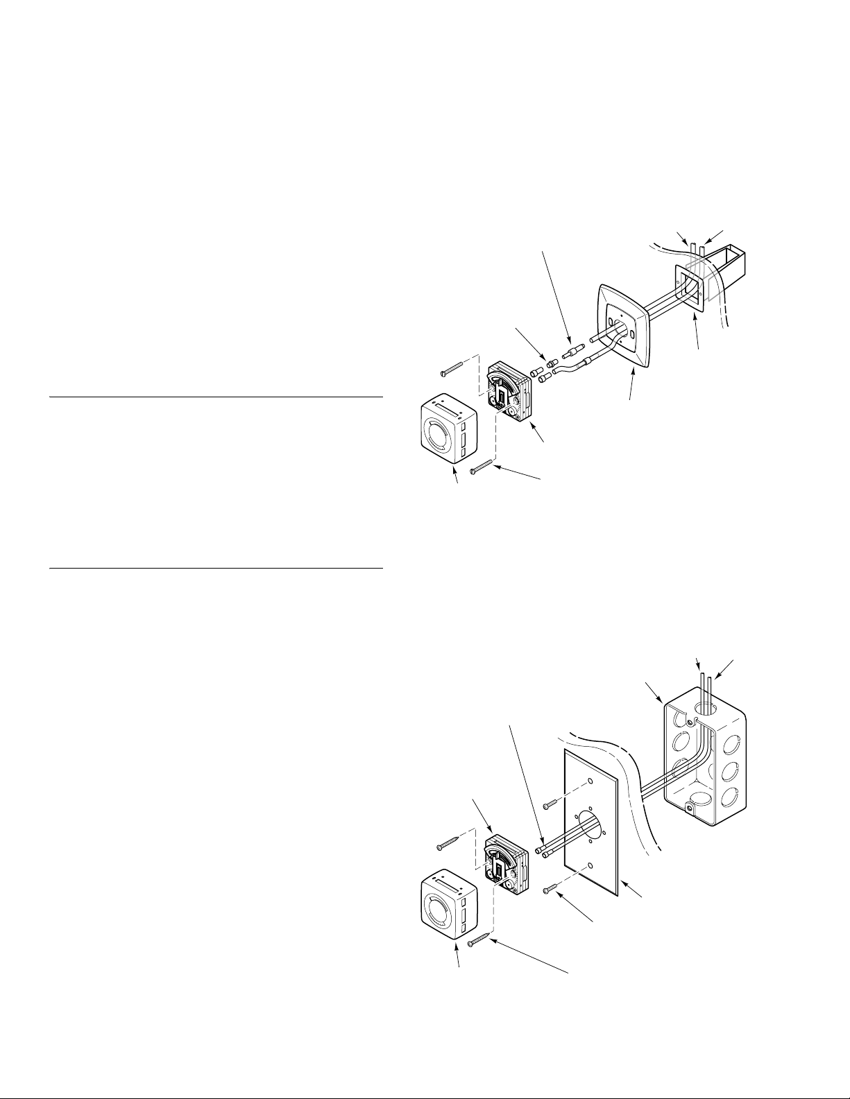
1. Mount the thermostat according to the applicable figure
(Figure-2 through Figure-8). See Figure-11 for mounting
dimensions.
1/4 x 3/16 in. Barbed Coupling
21-611
for Plastic Tubing
(included with thermostat)
20-693
6 in. Tube Assembly
with Eyelets
(included with
thermostat)
¡
F
¡
1
C
2
6
5
2
2
Thermostat
Cover
(order separately)
Mounting Screws
(included with thermostat)
Figure-2 Flush Mounting of Thermostat,
Using Drywall Mounting Bracket.
20-714
Wall Plate
(included with
thermostat)
Polyethylene
Tubing Air Supply
Branch
21-473
Drywall Mounting
(order separately)
Main
Locate the thermostat where it will be exposed to an
unrestricted circulation of air, which represents the average
temperature of the controlled space.
6 in. Tube Assembly with Eyelets
20-693
(included with thermostat)
Thermostat
¡
F
¡
1
C
2
6
5
2
2
Cover
(order separately)
Polyethylene Tubing
Pre-plumbed
Electrical Box
Wall
20-850 Plate
(2) Screws for Electrical
Box Mounting
(2) #6 Self-Tapping
Screws
Air Supply
Branch
Main
Figure-3 Flush Mounting of Thermostat, Using 20-850 Plate
and Pre-Plumbed Electrical Box.
4 © Copyright 2006 TAC All Rights Reserved. F-24579-2
Page 5
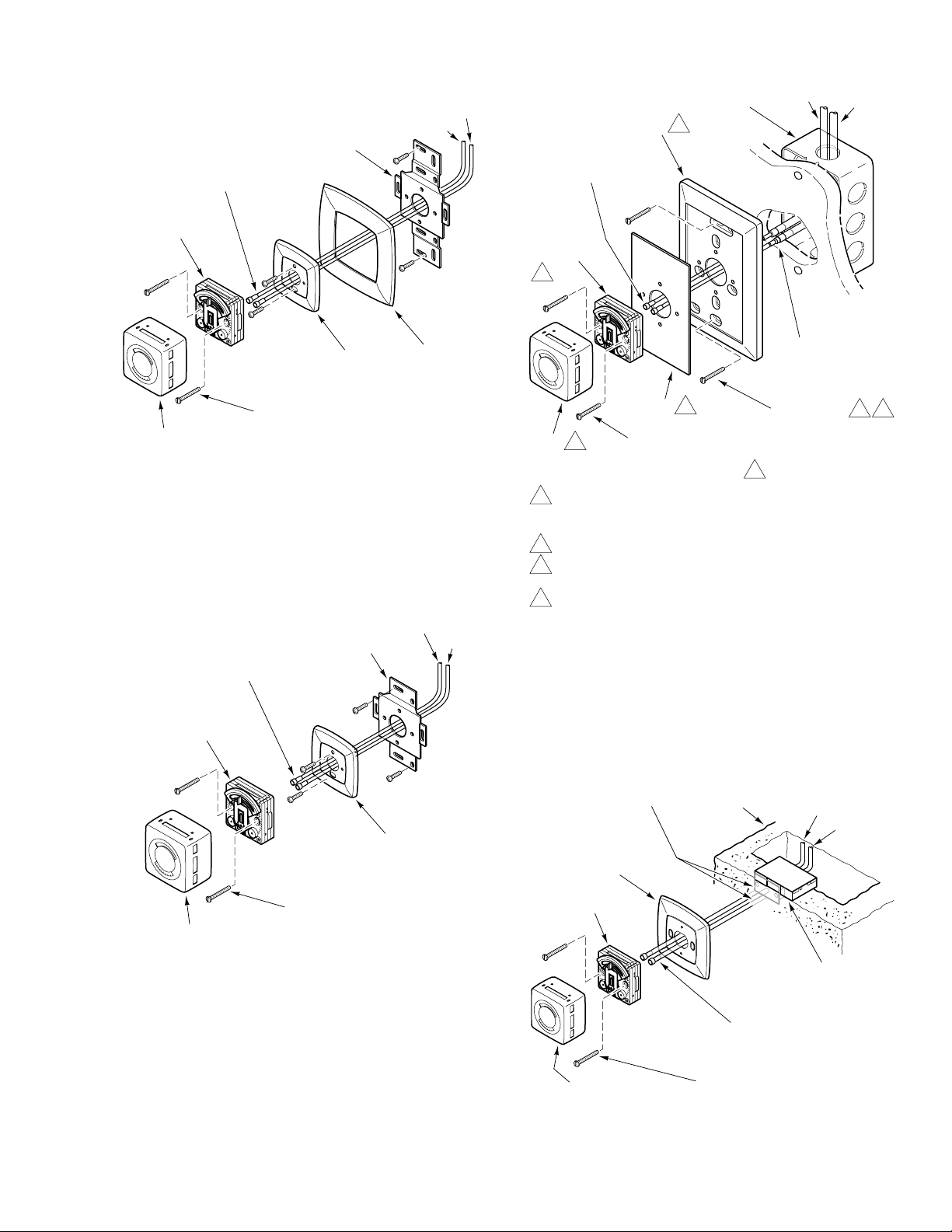
20-693
Bracket
6 in. Tube Assembly with Eyelets
(included with thermostat)
Thermostat
¡
F
¡
1
C
2
6
5
2
2
Wall Plate
Mounting Screws
Cover
(order separately)
(included with thermostat)
Figure-4 Thermostat Mounted with 22-022
Conversion Kit, Using Wall Plate and Skirt, to
Replace Competitive Thermostats.
6 in. Tube Assembly with Eyelets
20-693
(included with thermostat)
Bracket
Polyethylene Tubing
Air Supply
Main
Branch
Skirt
Polyethylene Tubing
Air Supply
Branch
Main
Air Supply Tubing
Branch
Main
Wall Plate
Pre-plumbed
Electrical Box
(optional)
2
3/16 in. Tygothane
Tubing with Eyelets
(included with thermostat)
Wall
Thermostat
1
¡
F
¡
1
C
2
6
5
2
2
3/16 in. x 1/4 in.
Barbed Coupling
(included with thermostat)
2
Insert
(2) #6 x 1 in.
2 4
Mounting Screws
Cover
1
(2) Thermostat
(for electrical box mounting)
Mounting Screws
(included with thermostat)
3
1 The pneumatic thermostat replacement kit 2218-632 includes
a thermostat, a 22-1033 Euro-white cover, and a 22-023
thermostat conversion kit.
2 Provided in the 22-023 thermostat conversion kit.
3 Optionally, the thermostat may be mounted with the #6 x 1 in.
self-tapping screws provided in the 22-023 kit.
4 Use the #8 x 1 in. mounting screws provided in the 22-023 kit
when mounting the wall plate directly to the wall, without an
electrical box.
Figure-6 Thermostat Mounted with 22-023 Thermostat
Conversion Kit.
Thermostat
¡
F
¡
1
C
2
6
5
2
2
Mounting Screws
Cover
(order separately)
(included with thermostat)
Figure-5 Thermostat Mounted with 22-022
Conversion Kit, Using Wall Plate Only, to
Replace Competitive Thermostats.
Wall Plate
Remove Locator
and Adaptor
20-714
Wall Plate
(included with
thermostat)
Thermostat
¡F
¡C
1
2
6
5
2
2
Cover
(order separately)
Figure-7 Thermostat Installation Using
Block
20-693
6 in. Tube Assembly with Eyelets
(included with thermostat)
Mounting Screws
(included with thermostat)
Pipehead in Masonry Wall.
Polyethylene
Tubing
Air Supply
Branch
Main
20-710
Mortar Joint Fitting
(order separately)
F-24579-2 © Copyright 2006 TAC All Rights Reserved. 5
Page 6
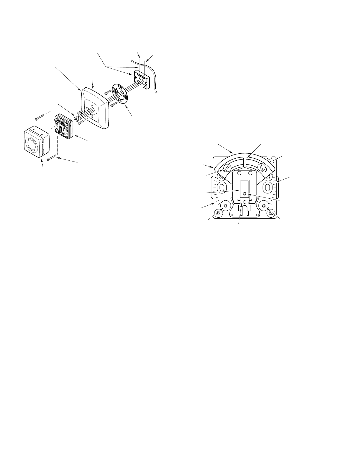
Polyethylene
w
Tubing
Air Supply
Branch
Main
20-716
20-689
Mounting Fitting with
8 ft. Copper Lines
(order separately)
Insulating Back Plate
(order separately)
Cutouts
(partially formed
on underside)
20-693
6 in. Tube Assembly
with Eyelets
(included with
thermostat)
¡
F
¡
1
C
2
6
5
2
2
20-642
Mounting Ring and
Flathead Screws
(order separately)
Thermostat
Mounting Screws
Cover
(included with thermostat)
(order separately)
Figure-8 Surface Mounting of Thermostat,
Pipehead Application.
Optional Mounting
Eliminate the pipehead fitting by using the 22-022 thermostat
conversion kit and the included instructions, plus the
following:
1/4" Plastic Air Lines: Install the 1/4" barbed couplings into
the air lines. Connect the tube assembly to the 3/16" end of
these couplings.
1/4" Copper Air Lines: Solder the barbed couplings into the
copper lines. The tube assembly can then be connected to
the 3/16" end of the couplings.
CALIBRATION
Calibration of Single Bimetal Models
The 2218 series thermostats are factory calibrated with the
throttling range set at 3 °F. They should not require
calibration upon installation. However, if the throttling range
is changed, or if limited summer control action at 8 psig main
air pressure is required, recalibrate the thermostat as follows:
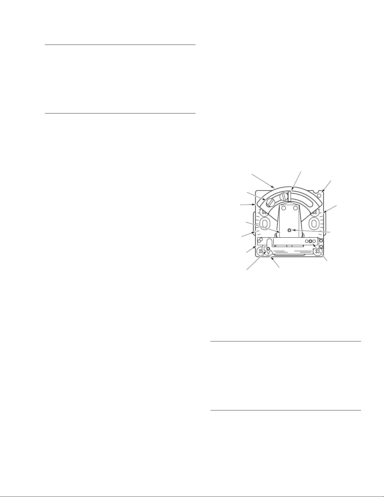
1. Remove the thermostat cover and install a 22-138 branch
tap gauge adaptor into the branch pressure tap hole
(Figure-9).
2. Measure the ambient temperature with an accurate
thermometer. This temperature
of the thermostat
. Take care not to breathe on, or place
a hand near the bimetals, as this will result in an
inaccurate reading.
3. Move the setpoint adjustment to the measured ambient
temperature, using the internal setpoint indicator.
must be within the range
Standard Calibration
1. Taking care not to breathe on, or place the hand near the
bimetal, use a 20-881 thermostat wrench (1/16” hex
wrench) to turn the reverse acting calibration screw until
the branch line pressure indicates 12 psig. Clockwise
rotation increases the branch line pressure.
Counterclockwise rotation decreases the branch line
pressure.
2. Raise the main air pressure to 25 psig.
3. Turn the direct acting calibration screw until the test
gauge indicates 12 psig. Clockwise rotation decreases
the branch line pressure. Counterclockwise rotation
increases the branch line pressure.
Cover Scale
Setpoint Adjustment
Setpont Indicator
Branch
Internal Setpoint
Indicator
Limit Stops (2)
(Accessory)
Thermostatic
Bimetal
Fahrenheit
T R
˚F ˚C
12
6
2
H
5
2
Pressure
Tap
Celsius
Scale
Reverse Acting
Calibration Scre
Scale
Direct Acting
Calibration Screw
Throttling Range
Switch-over
Calibration Screw
Adjustment Slide
Figure-9 Single Bimetal Thermostat Calibration
Features and Limit Stop Accessory.
Special Calibration — 8 psig Summer Control
1. Set the main air pressure to 8 psig.
2. Taking care not to breathe on, or place the hand near the
bimetal, use a 20-881 thermostat wrench (1/16” hex
wrench) to turn the reverse acting calibration screw until
the branch line pressure indicates 6 psig. Clockwise
rotation increases the branch line pressure.
Counterclockwise rotation decreases the branch line
pressure.
3. Raise the main air pressure to 25 psig.
4. Turn the direct acting calibration screw until the test
gauge indicates 6 psig. Clockwise rotation decreases the
branch line pressure. Counterclockwise rotation
increases the branch line pressure.
6 © Copyright 2006 TAC All Rights Reserved. F-24579-2
Page 7
Switch Over Point Adjustment
If necessary, adjust the switch point as follows:
Note:
• The switch point adjustment requires changes to the
main air pressure, which could affect other parts of the
system. This adjustment should instead be made on a
test bench at which a variable main air supply is
available.
• Install a test gauge into the branch line, so that this
pressure can be measured while making the switch
point adjustment.
1. Set the main air pressure to the desired switch over point.
2. Move the setpoint adjustment to its farthest clockwise
position.
3. Use a 20-881 thermostat wrench (1/16” hex wrench) to
turn the switch over calibration screw, 1/8 turn at a time,
until the branch pressure just drops to 0 psig. This sets
the switch over point.
4. Recalibrate the thermostat according to the instructions
in Standard Calibration or Special Calibration, as
applicable.
5. Reinstall the thermostat cover and set the thermostat to
the desired setpoint.
Calibration of Dual Bimetal Models
The 2218-301 thermostat is factory calibrated and should not
require calibration upon installation. However, if the summer
or winter setpoint requires calibration, or if the switch point
needs to be raised or lowered, recalibrate the thermostat as
follows:
1. Remove the thermostat cover and install a 22-138 branch
tap gauge adaptor and a suitable 0 to 30 psig gauge into
the branch pressure tap hole (Figure-10).
2. Measure the ambient temperature with an accurate
thermometer. This temperature
of the thermostat
. Take care not to breathe on, or place
a hand near the bimetals, as this will result in an
inaccurate reading.
Summer Setpoint Calibration
1. Position the summer setpoint cam to the measured
ambient temperature (Figure-10).
2. Set the main air pressure to 16 psig.
3. Adjust the summer calibration screw, using a 20-881
thermostat wrench (1/16” hex wrench), until the branch
tap gauge reads 9
the branch line pressure. Counterclockwise rotation
decreases the branch line pressure.
±1 psig. Clockwise rotation increases
must be within the range
3. The winter setpoint is in calibration when the winter
setpoint dial indicates the ambient temperature within
±2 °F. If not, adjust the winter setpoint as follows:
a. Rotate the winter setpoint screw until the dial gently
contacts its stop. Clockwise rotation increases the
ambient temperature reading, and counterclockwise
rotation decreases the ambient temperature reading.
b. Continue rotating the setpoint screw approximately
1/8 turn, slippint the screw inside the dial.
c. Turn the setpoint screw back and check for 9 ±1 psig
branch air pressure, with the dial indicating the
ambient temperature within ±2 °F.
d. Repeat steps a, b, and c, as necessary, until winter
setpoint calibration is obtained.
4. The winter setpoint screw may now be used to position
the dial to the desired winter control point.
Cover Scale
Setpoint Adjustment
Limit Stops (2)
(Accessory)
Summer
Setpoint
Summer
Bimetal
Fahrenheit
Scale
Winter
Bimetal
Winter Calibration and
Setpoint Screw
Setpont Indicator
2
Winter Setpoint Dial
Branch
Pressure
Tap
Celsius
Scale
Summer
Calibration
Screw
Switching
Screw
Figure-10 Dual Bimetal Thermostat Calibration
Features and Limit Stop Accessory.
Switch Over Point Adjustment
Adjust the switch over point as follows:
Note:
• The switch point adjustment requires changes to the
main air pressure, which could affect other parts of the
system. This adjustment should instead be made on a
test bench at which a variable main air supply is
available.
• Install a test gauge into the branch line, so that this
pressure can be measured while making the switch
point adjustment.
Winter Setpoint Calibration
1. Increase the main air pressure to 25 psig.
2. Using a 20-881 thermostat wrench (1/16” hex wrench),
rotate the winter calibration screw until the branch tap
gauge reads 9
branch line pressure. Counterclockwise rotation
±1 psig. Clockwise rotation increases the
1. Set the main air pressure to 15 psig.
2. Position the summer setpoint dial to 85 °F and the winter
setoint dial to 44 °F.
3. The branch tap gauge should read 15 psig, minimum. If
not, recheck the summer setpoint calibration.
decreases the branch line pressure.
F-24579-2 © Copyright 2006 TAC All Rights Reserved. 7
Page 8
4. Slowly increase the main air pressure until the branch
tap gauge drops to 0 psig. This is the main air pressure
at which the thermostat switches from summer control to
winter control.
5. If the main air pressure at the switching point is less than
17 psig or greater than 21 psig, adjust the switching
screw as follows, using a 20-881 thermostat wrench
(1/16” hex wrench):
a. If the switching point is less than 17 psig, turn the
switching screw 1/8 turn counterclockwise, to raise
the switching point. Raise the main air pressure until
the branch tap gauge reading drops to 0 psig
(switching point). If the main air pressure at this point
is still less than 17 psig, repeat this step, as
necessary, until the switching point is obtained.
b. If the switching point is greater than 21 psig, turn the
switching screw 1/8 turn clockwise, to lower the
switching point. Lower the main air pressure until the
branch tap gauge reading drops to 0 psig (switching
point). If the main air pressure at this point is still
greater than 21 psig, repeat this step, as necessary,
until the switching point is obtained.
4. Move the setpoint adjustment to the desired
temperature, using the internal setpoint indicator.
5. Slide the stops to the desired limits and tighten both
screws.
MAINTENANCE
The thermostat requires no maintenance.
Regular maintenance of the total system is recommended to
assure sustained, optimum performance.
FIELD REPAIR
None. Replace an inoperative thermostat with a functional
unit.
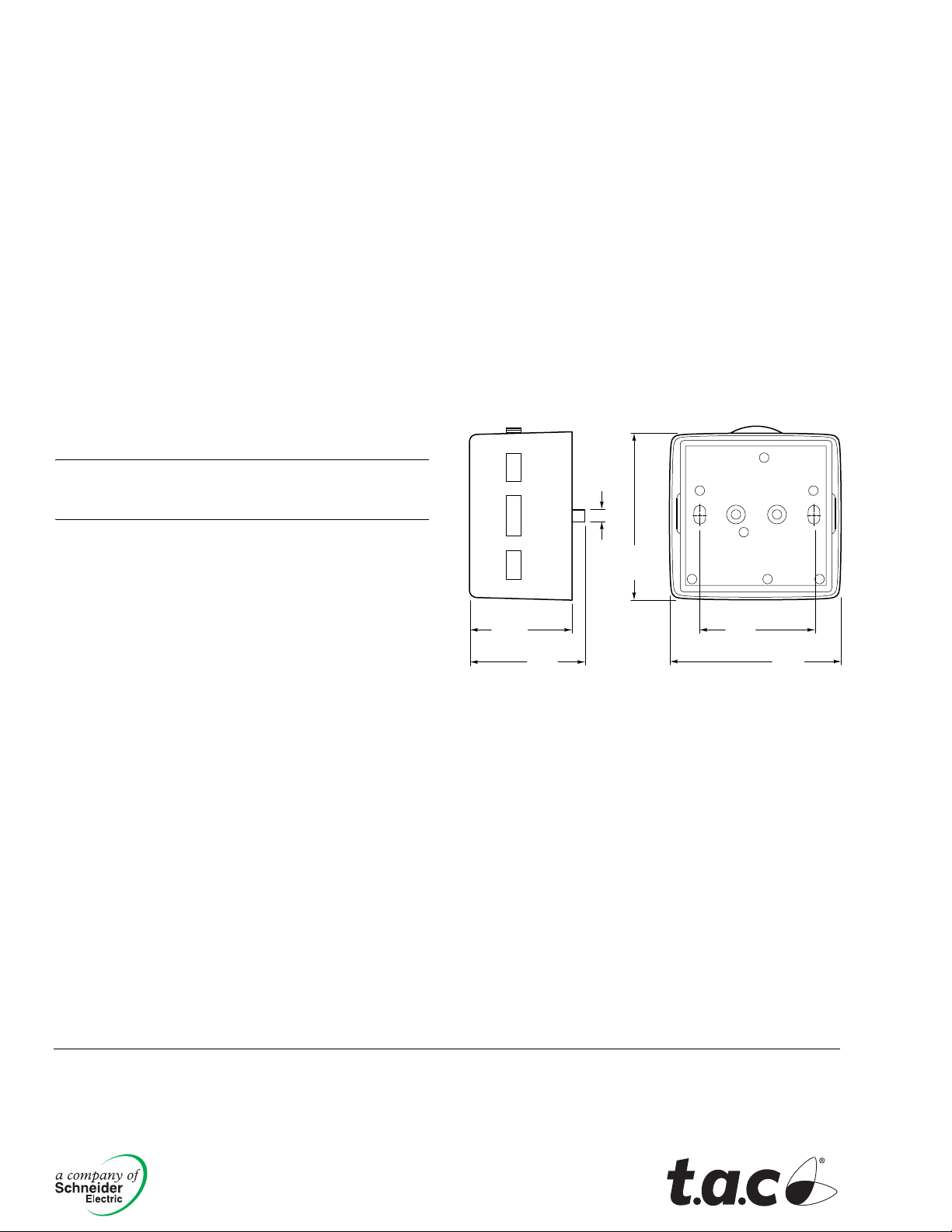
DIMENSIONAL DATA
Caution:
Do not force the calibrating screws. If the desired
action is not obtained when the screw is rotated, check to be
sure the direction of rotation is correct.
6. Reinstall the thermostat cover and set the thermostat to
the desired setpoint.
Concealed Adjustment
If concealment of the setpoint adjustment is required, install
a 21-800 (black) or 21-801 (Euro-white) setpoint adjustment
cover as follows:
1. Remove the thermostat cover.
2. Insert the adjustment cover through the slot at the top of
the cover and bend the tangs outward on the inside of
the cover.
3. Reinstall the cover onto the thermostat.
Internal Stop Kit (Accessory)
The internal stop kit, model 20-712, consists of two screws
and two nuts (Figure-9 and Figure-10). Install this kit as
follows:
1. Move the setpoint adjustment to one extreme limit.
2. Place a nut in the depression in the top plate and move
the adjustment cam over the nut, to where the slot in the
cam exposes the threads of the nut.
3. Thread a stop screw into the nut far enough to allow the
stop to slide in the slot. Repeat on the other side.
1/8
(.318)
2-1/32
(5.16)
1-1/4
(3.18)
1-3/8
(3.5)
Dimensions are in inches (mm).
Figure-11 Mounting Dimensions.
MB
1-3/8
(3.5)
2-1/32
(5.16)
Copyright 2006, TAC
All brand names, trad emarks and registered
trademarks are the property of their respective
owners. Information contained within this
document is subject to change without notice.
F-24579-2
TAC
1354 Clifford Avenue
P.O. Box 2940
Loves Park, IL 61132-2940
www.tac.com
 Loading...