

Page 1

Quick Start Guide
Model A10160
45MHz, 34Vp-p Single Channel
Wideband Amplifier
Publication No. 140724
Rev. 1.1
Tabor Electronics Ltd.
P.O. Box 404, NESHER Israel 3688809
Tel: +972-4-821-3393, FAX: +972-4-821-3388
Copyright 2016 by Tabor Electronics Ltd. Written in Israel. All rights reserved. This book or parts thereof may
not be reproduced in any form without written permission of the publisher.
Page 2

A10160 Feature
Highlights
45MHz bandwidth
High amplitude to 34Vp-p into 50Ω
High output current drive to 1A
Fast transition time of <10ns
Small footprint, all metal case
Custom gain configuration
Low distortion
Introduction
Model A10160 is an ultra-small footprint, wideband, DC coupled
amplifier designed for high frequency, high current, signal
amplification. With a high bandwidth of 45MHz, 34Vp-p into 50
ohms and up to 10W output power, the A10160 is the ideal
complimentary amplifier to any signal source that needs a
supporting power boost for demanding applications.
The A10160 was designed as a “Snap-On” accessory for the Tabor
WaveXciter series and models WS8351/2, both having a maximum
amplitude of 4Vp-p, which can be limiting for some applications,
requiring higher voltage and current to drive their UUT. Combined
with the A10160 the WX and WS models will now offer even higher
abilities to solve demanding application requiring up to 45MHz
signals at 34Vp-p into 50 ohms loads, without compromising their
signal integrity.
Tip
Knowing your source impedance is very important,
because the output gain accuracy is calibrated to
specific source impedance and therefore, any
unmatched load impedance may have an affect on
output level accuracy.
CAUTION
Applying the output signal on inductive or
Quick Start Guide
Figure 1, Model A10160
2
Page 3

A10160
capacitive loads may damage the amplifier.
Configuration
Options
The A10160’s standard configuration enables a maximum output
voltage of 34Vp-p into 50 ohms and a gain of x10. Custom gain of
x15 or x20 can be ordered.
WARNING
This manual has no schematics and no
instructions how to modify the amplifier for other
configurations as any configuration change,
without full engineering supervision, may affect
the performance of the amplifier. All options must
be specified at the time of your purchase.
Reconfiguration of fielded instruments can be
done by qualified and trained persons only.
Connectors
The A10160 has two front panel SMA input connectors, normal and
complement, which match the Tabor’s WX series and WX8351/2
outputs locations. The A10160 normal input should be connected to
the normal output of the signal source. The complement input
should be connected to the complement output of the signal source
as it is terminated to 50 ohms, in order to prevent undesired
aberrations from the differential signal source. However, if the
signal source does not have a differential output the A10160
complement output does not have to be connected. At the rear
panel, the A10160 has one BNC output connector, which outputs
the amplified signals and the power DIN-5 input connector, which is
fed from a factory supplied power supply.
Power Supply
The A10160 comes with a factory supplied power supply, which
accepts any voltage from 100 to 240Vac and there is no need to
select the voltage range between different countries. To avoid
potentially hazardous situations, always connect the center pin of
the power supply plug to mains ground using the line cord that is
supplied with the instrument.
Specifications
The specifications listed in this guide represent the performance
standards or limits against which the A10160 is tested.
Specifications apply under the following conditions: output
terminated into 50 ohms impedance, after 30 minutes of warm up
time, and within a temperature range of 20C to 30C.
Specifications outside of the temperature range are degraded by
0.1% per C.
3
Page 4
Quick Start Guide
Operating
Environment
The A10160 is intended for indoor use only and should be operated
in a clean, dry environment with an ambient temperature within the
range of 0 °C to 40 °C.
WARNING
The A10160 must not be operated in explosive,
dusty, or wet atmospheres. Avoid installation of
the module close to strong magnetic fields.
Performance
Checks
The instrument has been inspected for mechanical and electrical
performance before shipment from the factory. It is free of physical
defects and in perfect electrical order. Check the instrument for
damage in transit and perform the electrical procedures outlined in
the section entitled Unpacking and Initial Inspection.
Safety
Considerations
The Model A10160 has been manufactured according to
international safety standards. The instrument meets EN61010-1
standards for safety of commercial electronic measuring and test
equipment for instruments with an exposed metal chassis that is
directly connected to earth via the chassis power supply cable.
WARNING
Do not remove instrument covers when operating the
instrument or when the power cord is connected to the
mains.
Any adjustment, maintenance and repair of an opened, powered-on
instrument should be avoided as much as possible, but when
necessary, should be carried out only by a skilled person who is
aware of the hazard involved.
Supplied
Accessories
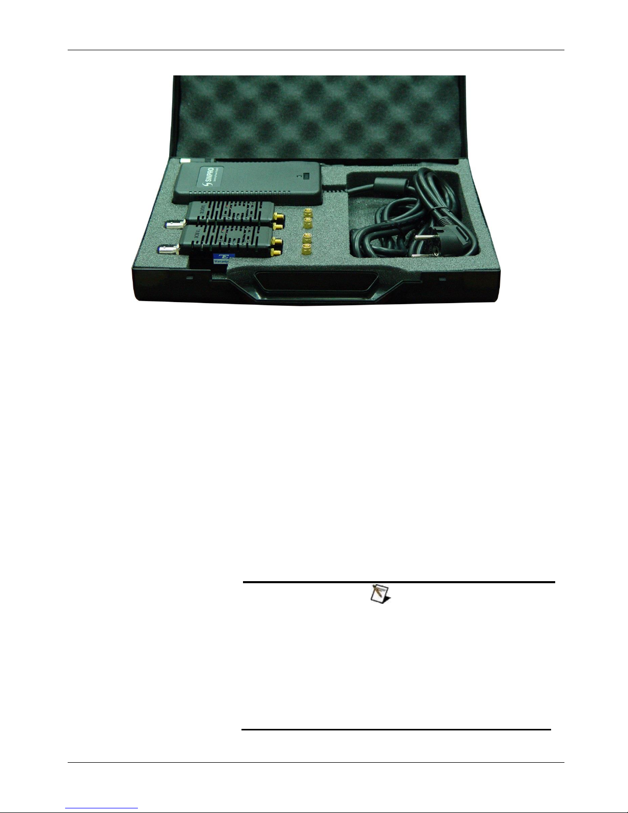
The A10160 is supplied with a power supply, power cord, two
SMA/M to SMA/M connectors to tie the A10160 to the instrument,
and in some cases, a “Y” splitter cable to connect two A10160 to
the same power supply mains.
4
Page 5
A10160
Long Term Storage
or Repackaging for
Shipment
If the A10160 is to be stored for a long period of time or shipped to
a service center, proceed as directed below. If repacking
procedures are not clear to you or, if you have questions, contact
your nearest Tabor Electronics Representative, or the Tabor
Electronics Customer Service Department.
1. Repack the instrument using the wrappings, packing material
and accessories originally shipped with the unit. If the original
container is not available, purchase replacement materials.
2. Be sure the carton is well sealed with strong tape or metal
straps.
3. Mark the carton with the model and serial number. If it is to
be shipped, show sending and return address on two sides of
the box.
NOTE
If the instrument is to be shipped to Tabor Electronics
for calibration or repair, attach a tag to the instrument
identifying the owner. Note the problem, symptoms, and
service or repair desired. Record the model and serial
number of the instrument. Show the RMA (Returned
Materials Authorization) order as well as the date and
method of shipment. ALWAYS OBTAIN AN RMA
NUMBER FROM THE FACTORY BEFORE SHIPPING THE
UNIT TO TABOR ELECTRONICS.
Figure 3, 2 x A10160 kit for dual channel unit
5
Page 6
Quick Start Guide
Unpacking and
Initial Inspection
Unpacking and handling of the A10160 requires normal precautions
and procedures applicable to handling of sensitive electronic
equipment. The contents of all shipping containers should be
checked for included accessories and certified against the packing
slip to determine that the shipment is complete.
Installation &
Operating
Instructions
Being a passive device, there are no controls, nor computer
programming required to operate the A10160. The following
procedure is recommended for proper installation of the A10160
with the Tabor WX series and WS8351/2 models, however, model
A10160 can be used in conjunction with any signal source, simply
by using cables to connect to the amplifier:
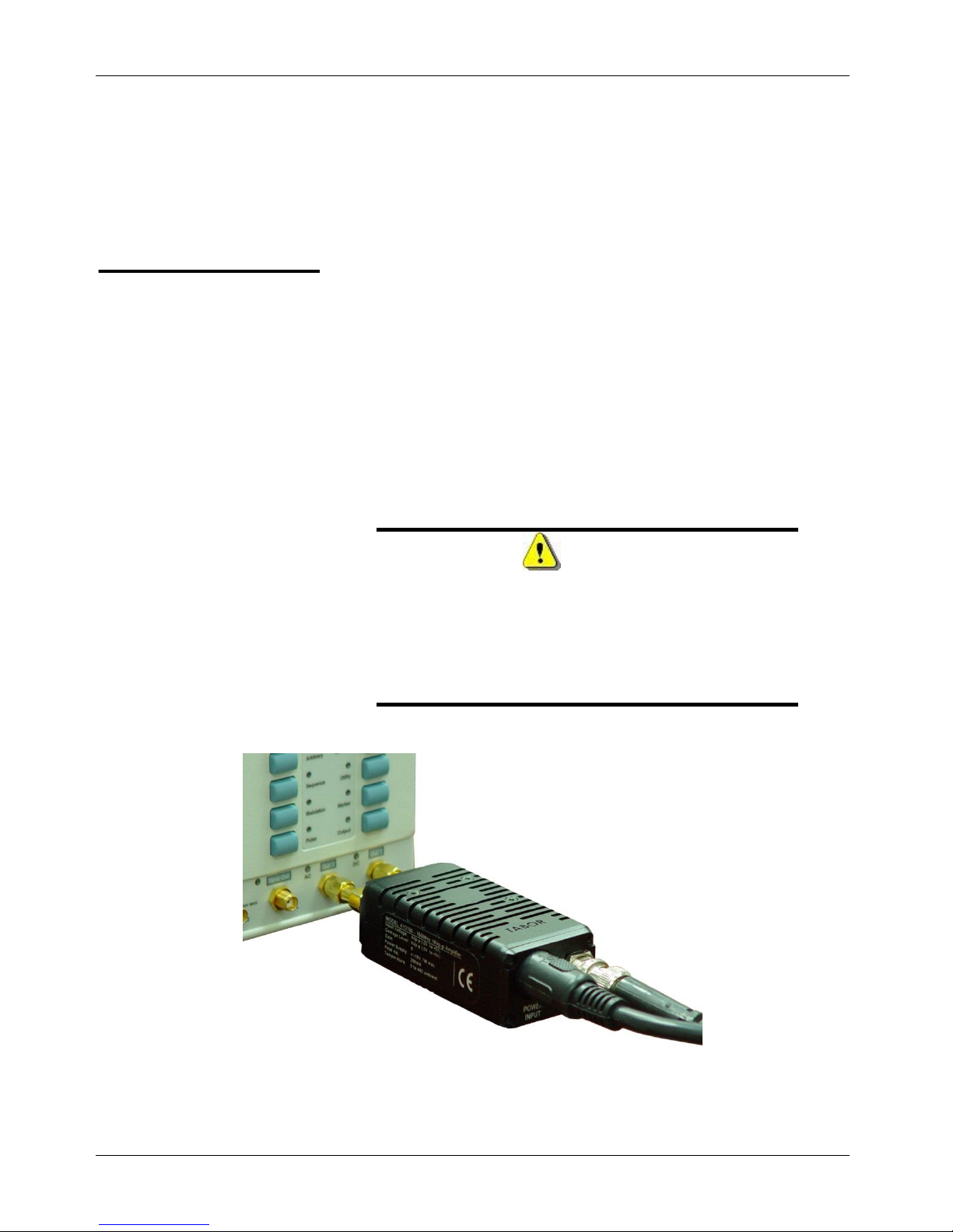
1. Connect the input terminals to your source, using the
supplied SMA/M to SMA/M connectors, as shown in figure 2.
2. Connect the output terminal to your load
3. Connect the power input terminal to the supplied power
supply
WARNING
There is no switch control to turn A10160
amplification on and off and therefore, the
amplifier is active immediately after you power it
up. Always make sure your load is protected from
inadvertent power up conditions before you turn
on your A10160.
6
Figure 2, Connecting the A10160 to Tabor WX or WS8351/2 unit
Page 7

A10160
Characteristics
Description
No. of Channels
1, (Differential; normal and inverted)
Connector
Rear panel SMA
Impedance
50Ω ± 1%
Coupling
DC
Damage Level
6Vp-p (-3V to +3V peaks)
Characteristics
Description
No. of Channels
1
Coupling
DC coupled
Connector
Front panel BNC
Gain (load 50Ω)
X10, fixed (X15 or X20 gain optional)
Polarity
Normal
Impedance
2.5Ω ± 5%
Protection
Short Circuit to Case Ground & Thermal protection
Amplitude
Peak
34Vpp into 50Ω
Continuous
30Vpp into 50Ω
Max. Output Current
Peak
1A
Continuous
750mA
Rise/Fall Time
30V step
<10ns (typ.)
Aberration
10Vpp
<5%
30Vpp
<10%
Characteristics
Description
Frequency Range
DC to 45MHz
Bandwidth (-3dB)
50Ω Load
<10Vpp
45MHz (typ.)
<34Vpp
30MHz (typ.)
Harmonics & Non-Harmonic
Distortion (typ.)
10Vpp
25Vpp
1MHz
<-58dBc
<-54dBc
10MHz
<-45dBc
<-45dBc
30MHz
<-42dBc
<-30dBc
Electrical Specifications
Input Characteristics
Output Characteristics
Frequency
7
Page 8

Quick Start Guide
Characteristics
Description
Power Supply
±20VDC
Power Consumption
20W
Signal Ground
Grounded to case ground
Characteristics
Description
Dimensions
40 x 30 x 110 mm (W x H x D)
Weight
Without package
115 g
Shipping weight 1 kit
1.25 Kg
Shipping weight 2 kit
1.45 Kg
Characteristics
Description
Temperature
Operating
0C to 50C
Storage
-40C to 70C
Humidity
85% RH, non-condensing
Characteristics
Description
Safety
IEC61010-1
EMC
IEC 61326-1:2006
Characteristics
Description
Warranty
1 year
Recalibration Period
2 years
Mechanical, Environmental and Maintenance Specifications
Power supply
Mechanical
Environmental
Certifications and compliances
Maintenance
8
 Loading...