

Page 1

User Manual
Model 9260
Dual Channel/Differential
Power Amplifier
Publication No. 041210
Rev 1.0
Tabor Electronics Ltd.
Tabor Electronics Ltd.
P.O. Box 404, Tel Hanan Israel 20302
Tel: +972-4-821-3393, FAX: +972-4-821-3388
PUBLICATION DATE: March 1, 2016
Copyright 2003 by Tabor Electronics Ltd. Printed in Israel. All rights reserved. This book or parts thereof may
not be reproduced in any form without written permission of the publisher.
Page 2

WARRANTY STATEMENT
Products sold by Tabor Electronics Ltd. are warranted to be free from defects in workmanship or materials.
Tabor Electronics Ltd. will, at its option, either repair or replace any hardware products which prove to be defective during the warranty period. You are a valued customer. Our mission is to make any necessary repairs
in a reliable and timely manner.
Duration of Warranty
The warranty period for this Tabor Electronics Ltd. hardware is three years, except software and firmware
products designed for use with Tabor Electronics Ltd. Hardware is warranted not to fail to execute its programming instructions due to defect in materials or workmanship for a period of ninety (90) days from the date
of delivery to the initial end user.
Return of Product
Authorization is required from Tabor Electronics before you send us your product for service or calibration.
Call your nearest Tabor Electronics support facility. A list is located on the last page of this manual. If you are
unsure where to call, contact Tabor Electronics Ltd. Tel Hanan, Israel at 972-4-821-3393 or via fax at 972-4821-3388. We can be reached at: [email protected]
Limitation of Warranty
Tabor Electronics Ltd. shall be released from all obligations under this warranty in the event repairs or modifications are made by persons other than authorized Tabor Electronics service personnel or without the written
consent of Tabor Electronics.
Tabor Electronics Ltd. expressly disclaims any liability to its customers, dealers and representatives and to
users of its product, and to any other person or persons, for special or consequential damages of any kind and
from any cause whatsoever arising out of or in any way connected with the manufacture, sale, handling, repair, maintenance, replacement or use of said products.
Representations and warranties made by any person including dealers and representatives of Tabor Electronics Ltd., which are inconsistent or in conflict with the terms of this warranty (including but not limited to the limitations of the liability of Tabor Electronics Ltd. as set forth above), shall not be binding upon Tabor Electronics
Ltd. unless reduced to writing and approved by an officer of Tabor Electronics Ltd.
This document may contain flaws, omissions or typesetting errors. No warranty is granted nor liability assumed in relation thereto. The information contained herein is periodically updated and changes will be incorporated into subsequent editions. If you have encountered an error, please notify us at sup[email protected]. All specifications are subject to change without prior notice.
Except as stated above, Tabor Electronics Ltd. makes no warranty, express or implied (either in fact or by operation of law), statutory or otherwise; and except to the extent stated above, Tabor Electronics Ltd. shall have
no liability under any warranty, express or implied (either in fact or by operation of law), statutory or otherwise.
PROPRIETARY NOTICE
This document and the technical data herein disclosed, are proprietary to Tabor Electronics, and shall not, without express written permission of Tabor Electronics, be used, in whole or in part to solicit quotations from a competitive source
or used for manufacture by anyone other than Tabor Electronics. The information herein has been developed at private
expense, and may only be used for operation and maintenance reference purposes or for purposes of engineering evaluation and incorporation into technical specifications and other documents, which specify procurement of products from
Tabor Electronics.
Page 3
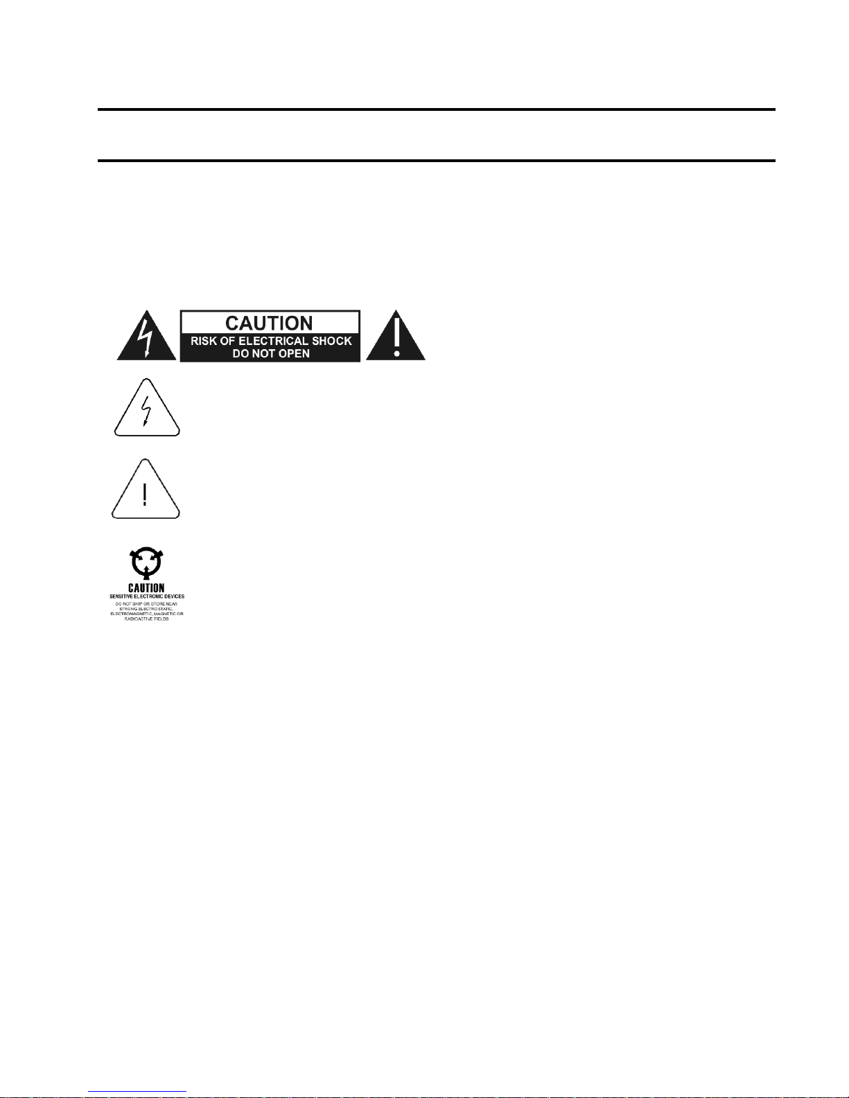
FOR YOUR SAFETY
Before undertaking any troubleshooting, maintenance or exploratory procedure, read carefully the WARNINGS and CAUTION notices.
This equipment contains voltage hazardous
to human life and safety, and is capable of
inflicting personal injury.
If this instrument is to be powered from the AC line (mains) through an autotransformer, ensure the common connector is connected to the neutral (earth
pole) of the power supply.
Before operating the unit, ensure the conductor (green wire) is connected to
the ground (earth) conductor of the power outlet. Do not use a two-conductor
extension cord or a three-prong/two-prong adapter. This will defeat the protective feature of the third conductor in the power cord.
Maintenance and calibration procedures sometimes call for operation of the
unit with power applied and protective covers removed. Read the procedures
and heed warnings to avoid “live” circuit points.
Before operating this instrument:
1. Ensure the proper fuse is in place for the power source to operate.
2. Ensure all other devices connected to or in proximity to this instrument are properly
grounded or connected to the protective third-wire earth ground.
If the instrument:
- fails to operate satisfactorily
- shows visible damage
- has been stored under unfavorable conditions
- has sustained stress
Do not operate until, performance is checked by qualified personnel.
Page 4

DECLARATION OF CONFORMITY
We: Tabor Electronics Ltd.
9 Hatasia Street, Tel Hanan
ISRAEL 36888
declare, that the 45MHz 34Vp-p Dual / Differential Channel Signal Amplifier
Model 9260
meet the intent of Directive 89/336/EEC for Electromagnetic Compatibility and the
requirements of the Low Voltage Directive 73/23/EEC amended by 93/68/EEC.
Compliance was demonstrated to the following specifications as listed in the official
Journal of the European Communities:
Safety:
IEC/EN 61010-1 2nd Edition:2001+ C1, C2
EMC:
EN 50081-1 Emissions:
EN 55022 - Radiated, Class B
EN 55022 - Conducted, Class B
EN 50082-1 Immunity:
IEC 801-2 (1991) - Electrostatic Discharge
IEC 801-3 / ENV50140 (1993) - RF Radiated
IEC 801-4 (1991) - Fast Transients
The tests were performed on a typical configuration.
Page 5

Table of Contents
Chapter 1 - PORTRAYAL
What’s in This Chapter ............................................................................................................................ 1-1
Introduction .............................................................................................................................................. 1-1
9260 Feature Highlights .......................................................................................................................... 1-2
Conventions Used in this Manual ............................................................................................................ 1-2
Functional ................................................................................................................................................ 1-3
Description ............................................................................................................................................... 1-3
Configuration Options .............................................................................................................................. 1-3
Specifications .......................................................................................................................................... 1-4
Front Panel .............................................................................................................................................. 1-4
Connectors .............................................................................................................................................. 1-4
Front Panel .............................................................................................................................................. 1-6
Indicators ................................................................................................................................................. 1-6
Rear Panel Parts and Connectors ........................................................................................................... 1-6
Operating ................................................................................................................................................. 1-8
Instructions .............................................................................................................................................. 1-8
Chapter 2 - INSTALLATION
Installation Overview ............................................................................................................................... 2-1
Unpacking and Initial Inspection .............................................................................................................. 2-1
Safety Precautions .................................................................................................................................. 2-1
Performance Checks ............................................................................................................................... 2-3
Operating Environment ............................................................................................................................ 2-4
Power Requirements ............................................................................................................................... 2-4
Grounding Requirements ........................................................................................................................ 2-5
Long Term Storage or Repackaging for Shipment ................................................................................. 2-5
Preparation for Use ................................................................................................................................. 2-6
Installation................................................................................................................................................ 2-6
Factory Configuration of the 9260 Settings ............................................................................................. 2-6
Field Configuration of the 9260 Settings ................................................................................................. 2-7
Page 6

Chapter 3 - MAINTENANCE, PERFORMANCE CHECKS and ADJUSTMENTS
What’s in This Chapter ............................................................................................................................. 3-1
Disassembly Instructions ......................................................................................................................... 3-1
Special Handling of Static Sensitive Devices .......................................................................................... 3-2
Cleaning ................................................................................................................................................... 3-3
Repair and Replacement ......................................................................................................................... 3-3
Performance Checks................................................................................................................................ 3-4
Environmental Conditions ........................................................................................................................ 3-4
Recommended Test Equipment .............................................................................................................. 3-4
Gain Accuracy Tests ................................................................................................................................ 3-5
Amplifier Bandwidth ................................................................................................................................. 3-6
Amplitude Accuracy ................................................................................................................................. 3-6
Amplifier Pulse Response ........................................................................................................................ 3-7
Pulse Response Checks .......................................................................................................................... 3-7
Auxiliary Input ........................................................................................................................................... 3-8
Auxiliary Offset Checks ............................................................................................................................ 3-8
Auxiliary Input Checks.............................................................................................................................. 3-9
Adjustment Procedures .......................................................................................................................... 3-10
Amplifier Gain Adjustments .................................................................................................................... 3-10
Gain Adjustments ................................................................................................................................... 3-10
Pulse Response Adjustments ................................................................................................................ 3-11
Pulse Adjustments ................................................................................................................................. 3-11
Appendix A - SPECIFICATIONS ................................................................................................................. A-1
ii
Page 7

List of Figures
1-1, The Model 9260 ............................................................................................................................... 1-3
1-2, The 9260 Rear Panel ....................................................................................................................... 1-6
2-1, Field Modification of Channel 1 Input Impedance ............................................................................ 2-7
List of Tables
2-1, Input Impedance Jumpers ................................................................................................................ 2-7
2-2, Input coupling Jumpers .................................................................................................................... 2-8
2-3, Output coupling Jumpers ................................................................................................................. 2-8
3-1, Recommended Test Equipment ....................................................................................................... 3-5
3-2, Gain Accuracy Tests ........................................................................................................................ 3-6
3-3, Output Bandwidth Tests ................................................................................................................... 3-7
3-4, Square Wave Characteristics ........................................................................................................... 3-8
3-5, Square Wave Characteristics ........................................................................................................... 3-9
iii
Page 8

This page intentionally left blank
iv
Page 9

What’s in This
Chapter
This chapter contains general and functional description of the
Model 9260 dual/differential wideband power amplifier. It also
describes the front and rear panel connectors and its operational
modes. It also and provides description of all features available with
the instrument.
Introduction
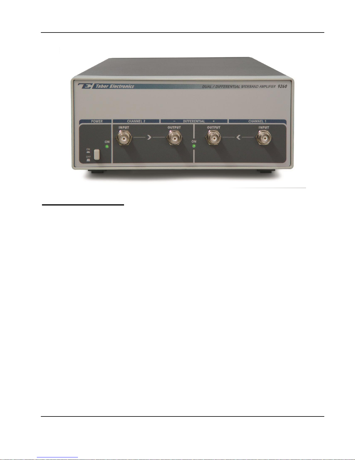
The Model 9260, as shown in Figure 1-1, is a bench-top, 2U, half
19” rack size, fully metal case dual channel amplifier. The
instrument can be configured to be used as two, single-ended and
independent channels, or as a one input with two differential
outputs.
The inputs to the amplifiers be configured to match different source
impedances such as 50 , 75 , or 1 M. The output is driven
from a 0 source.
There are three inputs for each channel:
1. Main input. This input is located on the front panel and is
normally used for signal inputs.
2. Auxiliary input. This input is located on the rear panel and can
be used as a summing input.
3. DC Offset input. This input is also located on the rear panel and
can be used for offsetting the signal level within the specified
output level window.
The outputs are located on the front panel. There are two outputs,
one for each channel. When the 9260 is configured as two
separate amplifiers, the outputs generate amplified signals within
the range of 34 Vp-p.
Note
The output of the 9260 tends to oscillate if left open. The same may
occur if the signal is applied to a high impedance source.
The bandwidth of the amplifier is around 30 MHz for large signals.
Small signal bandwidth can reach 45 MHz.
The 9260 can be configured as a differential amplifier. In this case,
the channel 2 input is disabled and channel 1 input is amplified and
Chapter 1
PORTRAYAL
Page 10
User Manual 9260
distributed differentially to both outputs. In this case, channel 1
output generates in-phase signal while channel 2 outputs an
inverted signal that has exactly 180 phase offset to the normal
output. Full amplitude and bandwidth is preserved when the 9260
operates in differential mode. Using the differential mode, the 9260
does not sacrifice accuracy, nor does it sacrifice bandwidth.
The 9260 has two additional inputs for each channel allowing
summation of two signals and providing an external control of DC
level offset. These inputs are accessible from the rear panel only.
9260 Feature
Highlights
Bench-top, all metal case
Large signal bandwidth to 30 MHz
Small signal bandwidth to 45 MHz
High amplitude to 34Vp-p (high impedance)
Peak current to 1A
Continuous output power to 10 W
Low distortion
Conventions
Used in this
Manual
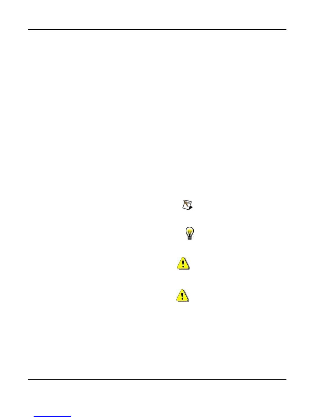
The following symbols may appear in this manual:
Note
A Note contains information relating to the use of this product
TIP
A Tip contains information relating to the performance of this product
Caution
A Caution contains information that should be followed to avoid personal
damage to the instrument or the equipment connected to it.
Warning
A Warning alerts you to a potential hazard. Failure to adhere to the
statement in a WARNING message could result in personal injury.
1-2 Portrayal
Page 11
User Manual 9260
Functional
Description
Detailed functional description of the features, operation and
options available with the 9260 is given in the following paragraphs.
The wideband amplifier can be ordered with different configurations
such as input impedance, gain, etc. Therefore read the following
description carefully and make sure your amplifier is configured
correctly for your application before you connect the cables to your
circuits.
Configuration
Options
The Model 9260 must be ordered from the factory already
configured for your application. This manual has no schematics and
no instructions how to modify the amplifier for other configurations
as any configuration change, without full engineering supervision,
may affect the performance of the amplifier. Below, you’ll find a list
of optional configurations for the amplifier:
Basic Configuration – defines if the 9260 will operate as two
single-ended and independent amplifiers, or as single input with
differential outputs.
Input Impedance – determines the matching source impedance at
the input connectors. Three options are available: 50, 75 and
1M. Input impedance can be configured for the front panel main
inputs and for the rear panel auxiliary inputs.
Gain – specifies gain magnitude of the input signal. Factory default
setting is 10. Custom gain can also be specified. Note that some
characteristics of the output section may change for gain setting
above 10.
Figure 1-1, The Model 9260
Portrayal 1-3
Page 12

User Manual 9260
As explained above, all options must be specified at the time of
your purchase and the 9260 is supplied fully configured.
Reconfiguration of fielded instruments can be done by qualified and
trained persons only.
Specifications
Instrument specifications are listed in Appendix A. These
specifications are the performance standards or limits against
which the instrument is tested. Specifications apply under the
following conditions: output terminated into load impedance, after
30 minutes of warm up time, and within a temperature range of
20C to 30C. Specifications outside of the temperature range are
degraded by 0.1% per C.
Front Panel
Connectors
The 9260 has 4 BNC connectors on its front panel, two for each
channel. Two are marked INPUT and the other two are marked
OUTPUT. These connectors are described below.
Channel 1 Input
The input connector accepts signals within the range of DC to over
35 MHz and amplifies them by a fixed gain. The gain is normally
x10 however, this number may be different if you ordered the
amplifier with different gain setting. Input impedance is factory preconditioned and has one of the following values: 50, or 1M.
1M input impedance can be used for low frequency signals (up to
100kHz) however, higher frequencies require 50 termination at
the input of the amplifier to eliminate standing waves and
reflections in the input cable, which can cause excessive ringing
and aberrations at the output.
The amplifier input cannot tolerate high voltage on its 50
resistance. Therefore, before applying the cable to the input
connector, make sure your signal will not exceed input rating, as
specified in Appendix A of this manual.
Note
Channel 1 Input only is used when the Model 9260
is configured to operate in differential mode.
1-4 Portrayal
Page 13
User Manual 9260
Channel 2 Input
This input connector accepts signals within the range of DC to over
35 MHz and amplifies them by a fixed gain. The gain is normally
x10 however, this number may be different if you ordered the
amplifier with different gain setting. Input impedance is factory preconditioned and has one of the following values: 50, or 1M.
1M input impedance can be used for low frequency signals (up to
100kHz) however, higher frequencies require 50 termination at
the input of the amplifier to eliminate standing waves and
reflections in the input cable, which can cause excessive ringing
and aberrations at the output.
The amplifier input cannot tolerate high voltage on its 50
resistance. Therefore, before applying the cable to the input
connector, make sure your signal will not exceed input rating, as
specified in Appendix A of this manual.
Note
Channel 2 Input is disabled when the 9260 is
configured to operate in differential output mode.
Channel 1 Output
The channel 1 output connector outputs amplified signals. When
the 9260 is configured as two separate amplifiers, this output
connector generates amplified signals that are applied to the
channel 1 input connector. If the instrument is configured for
differential output, this channel generates normal, non-inverted
signals while the other output connector generates the inverted
signal at 180 phase offset.
Gain at this output is fixed at 10 (or another gain factor that was
specified at the time of your purchase). Output source impedance
is 0.
WARNING
Applying the output signal on inductive or
capacitive loads may damage the amplifier.
Channel 2 Output
The channel 2 output connector outputs amplified signals. When
the 9260 is configured as two separate amplifiers, this output
generates amplified signals that are applied to the channel 2 input
connector. If the instrument is configured for differential output, this
channel generates an inverted signal at 180 phase offset while
channel 1 output generates the normal, non-inverted.
Gain at this output is fixed at 10 (or another gain factor that was
specified at the time of your purchase). Output source impedance
is 0.
Portrayal 1-5
Page 14
User Manual 9260
WARNING
Applying the output signal on inductive or
capacitive loads may damage the amplifier.
Front Panel
Indicators
The 9260 has 2 indicators on its front panel. The POWER LED will
light as soon as you press the switch to power up the 9260. An
illuminated power light designates power is applied to the
instrument and you should expect to have signal at its output
connector(s).
An LED at the center of the front panel is marked Differential ON.
When this light is on, channel 2 input is disabled and signal applied
to the channel 1 input is routed to both channel 1 and channel 2
outputs, except the signal is now differential. The differential mode
is selected with a rear panel switch.
Rear Panel Parts
and Connectors
The rear panel is rarely used for normal operation however, there
are some connections you must do before you can operate the
amplifier for example, connecting the mains power to the
instrument. There are other connectors and parts on the rear panel;
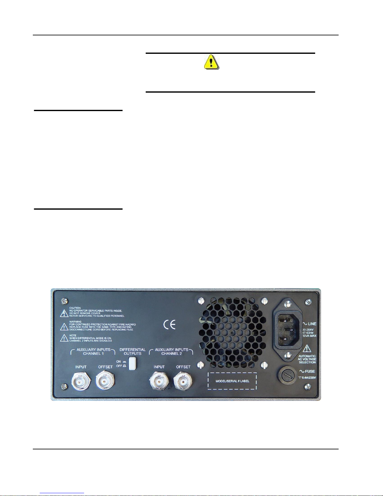
These are discussed in the following paragraphs. Refer to Figure 12 throughout the following description.
1-6 Portrayal
Figure 1-2, The 9260 Rear Panel
Page 15

User Manual 9260
Line Receptacle and
Fuse
Power is connected to the 9260 through the line receptacle. The
amplifier accepts any voltage from 80 to 265Vac and there is no
need to select the voltage range between different countries.
Instructions how to connect the line cord and how to replace the
line fuse is given in Chapter 2. If a fuse blows, make sure you
replace it with the same type and rating to avoid possible damage
to the product from unsuitable fuse value.
Auxiliary Inputs
Channel 1
There are two Channel 1 auxiliary inputs on the rear panel marked
INPUT and OFFSET.
The INPUT connector can be used as summing input to the front
panel signal. It also can be used as the main input if connectors are
available on the back only. However, the output is always from the
front panel connectors. Observe the input limitations as specified in
Appendix A to avoid damage to the amplifier circuit.
The OFFSET connector is used for dc signals only. Use this input
to offset your signal to any direction, positive or negative however,
always observe the positive and negative rail limitations as
specified in Appendix A to avoid damaging the amplifier circuits.
With normal configuration, this input is used for driving the front
panel output for channel 1 only. When the 9260 is configured for
differential outputs, channel 2 auxiliary inputs are disabled and only
channel 1 signal is amplified.
Auxiliary Inputs
Channel 2
There are two Channel 2 auxiliary inputs on the rear panel marked
INPUT and OFFSET.
The INPUT connector can be used as summing input to the front
panel signal. It also can be used as the main input if connectors are
available on the back only. However, the output is always from the
front panel connectors. Observe the input limitations as specified in
Appendix A to avoid damage to the amplifier circuit.
The OFFSET connector is used for dc signals only. Use this input
to offset your signal to any direction, positive or negative however,
always observe the positive and negative rail limitations as
specified in Appendix A to avoid damaging the amplifier circuits.
With normal configuration, this input is used for driving the front
panel output for channel 2 only. When the 9260 is configured for
differential outputs, these inputs are disabled and only channel 1
signal is amplified.
Portrayal 1-7
Page 16
User Manual 9260
Differential Outputs
Switch
The Differential Outputs switch has two actions. In normal mode, it
separates between the two channels so each channel can be used
separately. In Differential Mode, this switch disables channel 2
inputs and converts the internal circuits to output differential
signals. Channel 1 is used for outputting the normal output and
channel 2 is used for outputting the inverted signal. When this
switch is depressed, the front panel led illuminates, designating that
the differential mode has been selected.
Grounding
Considerations
Understanding how to connect your ground path could be critical to
preserving the integrity of your output signal. If you are using a
single-ended output then it will probably be safe for you to connect
the circuit ground to case ground. Always bear in mind the following
warning:
WARNING
Input and output grounds are tied together to case
ground and therefore, it is absolutely forbidden to
connect the output ground to a different level than
the input ground. Failure to adhere to this
limitation may damage the 9260 and the
surrounding equipment connected to its I/O
connectors.
Operating
Instructions
Being a passive device, there are no controls, nor computer
programming required to operate the Model 9260. The following
procedure is recommended for proper operation of the power
amplifier:
1. Make sure your box is configured for input and output
impedance and gain
2. Follow the installation instructions given in Chapter 2 of this
manual
3. Connect the output terminal to your load
4. Connect the input terminal to your source
5. Turn on power to your 9260
WARNING
There is no switch control to turn 9260
amplification on and off and therefore, the
amplifier is active immediately after you power it
up. Always make sure your load is protected from
inadvertent power up conditions before you turn
on your 9260.
1-8 Portrayal
Page 17
Chapter 2
Installation
Overview
This chapter contains information and instructions necessary to
prepare the Model 9260 for operation. Details are provided for initial
inspection, grounding safety requirements, repackaging instructions
for storage or shipment, installation information and Ethernet address
configuration.
Unpacking and
Initial Inspection
Unpacking and handling of the generator requires normal precautions
and procedures applicable to handling of sensitive electronic
equipment. The contents of all shipping containers should be checked
for included accessories and certified against the packing slip to
determine that the shipment is complete.
Safety
Precautions
The following safety precautions should be observed before using
this product. Although some instruments and accessories would
normally be used with non-hazardous voltages, there are situations
where hazardous conditions may be present.
CAUTION
This product is intended for use by qualified persons
who recognize shock hazards and are familiar with the
safety precautions required to avoid possible injury.
Read the operating information carefully before using
the product.
Exercise extreme caution when a shock hazard is present. Lethal
voltage may be present on power cables, connector jacks, or test
fixtures. The American National Standard Institute (ANSI) states that a
shock hazard exists when voltage levels greater than 30V RMS,
42.4V peak or 60 VDC are present.
CONFIGURING the INSTRUMENT
Page 18

User Manual 9260
WARNING
For maximum safety, do not touch the product, test cables, or any other instrument parts while power is applied to the circuit under test. ALWAYS remove power
from the entire test system before connecting cables or
jumpers, installing or removing cards from the computer, or making internal changes such as changing the
module address.
Do not touch any object that could provide a current
path to the common side of the circuit under test or
power line (earth) ground. Always keep your hands dry
while handling the instrument.
When using test fixtures, keep the lid closed while power is applied to
the device under test. Carefully read the Safety Precautions
instructions that are supplied with your test fixtures.
Before performing any maintenance, disconnect the line cord and all
test cables. Only qualified service personnel should perform
maintenance.
Performance
Checks
The instrument has been inspected for mechanical and electrical
performance before shipment from the factory. It is free of physical
defects and in perfect electrical order. Check the instrument for
damage in transit and perform the electrical procedures outlined in the
section entitled Unpacking and Initial Inspection.
2-2 Portrayal
Page 19

User Manual 9260
Operating
Environment
The 9260 is intended for operation on the bench or inside a rack of
instruments. It is intended for indoor use only and should be
operated in a clean, dry environment with an ambient temperature
within the range of 0 °C to 50 °C.
WARNING
The 9260 must not be operated in explosive, dusty, or
wet atmospheres. Avoid installation of the module
close to strong magnetic fields.
The design of the 9260 has been verified to conform to EN 61010-1
2nd addition safety standard per the following limits: Installation
(Overvoltage) Category I (Measuring terminals) Pollution Degree 2.
Installation (Overvoltage) Category I refers to signal level, which is
applicable for equipment measuring terminals that are connected to
source circuits in which measures are taken to limit transient
voltages to an appropriately low level.
Pollution Degree 2 refers to an operating environment where
normally only dry non-conductive pollution occurs. Occasionally a
temporary conductivity caused by condensation must be expected.
Power
Requirements
The amplifier may be operated from a wide range of mains voltage 90
to 264Vac. Voltage selection is automatic and does not require switch
setting. The instrument operates over the power mains frequency
range of 48 to 63Hz. Always verify that the operating power mains
voltage is the same as that specified on the rear panel.
The 9260 should be operated from a power source with its neutral at
or near ground (earth potential). The instrument is not intended for
operation from two phases of a multi-phase ac system or across the
legs of a single-phase, three-wire ac power system. Crest factor (ratio
of peak voltage to rms.) should be typically within the range of 1.3 to
1.6 at 10% of the nominal rms. mains voltage.
Portrayal 2-3
Page 20
User Manual 9260
Grounding
Requirements
To ensure the safety of operating personnel, the U.S. O.S.H.A.
(Occupational Safety and Health) requirement and good engineering
practice mandate that the instrument panel and enclosure be “earth”
grounded. Although BNC housings are isolated from the front panel,
the metal part is connected to earth ground.
WARNING
Do not attempt to float the output from ground as it may
damage the Model 9260 and your equipment.
WARNING
Input and output grounds are tied together and therefore, it is absolutely forbidden to connect the output
ground to a different level than the input ground. Failure
to adhere to this limitation may damage the 9260 and the
surrounding equipment connected to its I/O connectors.
Long Term Storage
or Repackaging for
Shipment
If the instrument is to be stored for a long period of time or shipped to
a service center, proceed as directed below. If repacking procedures
are not clear to you or, if you have questions, contact your nearest
Tabor Electronics Representative, or the Tabor Electronics Customer
Service Department.
1. Repack the instrument using the wrappings, packing material
and accessories originally shipped with the unit. If the original
container is not available, purchase replacement materials.
2. Be sure the carton is well sealed with strong tape or metal
straps.
3. Mark the carton with the model and serial number. If it is to
be shipped, show sending and return address on two sides of
the box.
NOTE
If the instrument is to be shipped to Tabor Electronics
for calibration or repair, attach a tag to the instrument
identifying the owner. Note the problem, symptoms, and
service or repair desired. Record the model and serial
number of the instrument. Show the RMA (Returned Materials Authorization) order as well as the date and
method of shipment. ALWAYS OBTAIN AN RMA
NUMBER FROM THE FACTORY BEFORE SHIPPING THE
9260 TO TABOR ELECTRONICS.
2-4 Portrayal
Page 21

User Manual 9260
Preparation for Use
Preparation for use includes removing the instrument from the
container box and connecting the cables to its input and output
connectors.
Installation
If this instrument is intended to be installed in a rack, it must be
installed in a way that clears air passage to its cooling fans. For
inspection and normal bench operation, place the instrument on the
bench in such a way that will clear any obstructions to its rear fan to
ensure proper airflow.
CAUTION
Using the 9260 without proper airflow will result in damage to the instrument.
Factory
Configuration of the
9260 Settings
When you order the Model 9260, you should provide details how you
want this product configured. There is some amount of flexibility in the
configuration before the instrument is shipped from the factory. The
following are factory configured settings:
Gain
The default gain setting is x10.
Input Impedance
The default input impedance is 50Ω. The 9260 can be ordered with
different input impedance values such as 75Ω and 1MΩ. The 1MΩ is
recommended for low frequency operation only as the high input
impedance degrades the frequency response of the amplifier.
Appendix A specifies the bandwidth for the various source and input
impedances.
Source (output) Impedance
The default source (output) impedance is 0Ω.
Input/Output Coupling
The default input/output coupling is DC. The 9260 can be ordered AC
coupled. DC coupling is recommended for signals that have dc
components with low frequencies operation. Appendix A specifies the
frequency limitation for inputs/outputs configured to AC coupling.
Single-ended/Differential Outputs
The default configuration is single-ended. With this configuration,
there are two independent channels that amplify signals that are
applied to the channel 1 and 2 inputs. The 9260 can be ordered with
differential outputs; In this case, channel 2 input is disabled and
channel 1 output is amplified and routed differentially to both channels
1 and 2. Channel 1 outputs the normal signal and channel 2 outputs
the inverted phase signal. Appendix A specifies the properties of the
9260 when configured for differential outputs operation.
Portrayal 2-5
Page 22
User Manual 9260
Field Configuration
of the 9260 Settings
Limited flexibility is available for you, as the user, to change 9260
configuration in the field. Changing configuration involves the opening
of the top cover and therefore, it is suggested that this operation be
completely avoided or, if absolutely necessary, should be carried out
by factory-trained person.
Use the following instructions to re-configure 9260 settings in the field:
Remove the Top Cover
There are four screws bolting the top cover to the case. These are
located on both sides of the cover. Identify and remove these screws.
Use Philips screwdriver only to remove the screws. Hold the cover
from both sides and pull upwards until the top is clear of the case
sides. Once the top cover is open, you’ll be able to access jumpers
that set the different configuration.
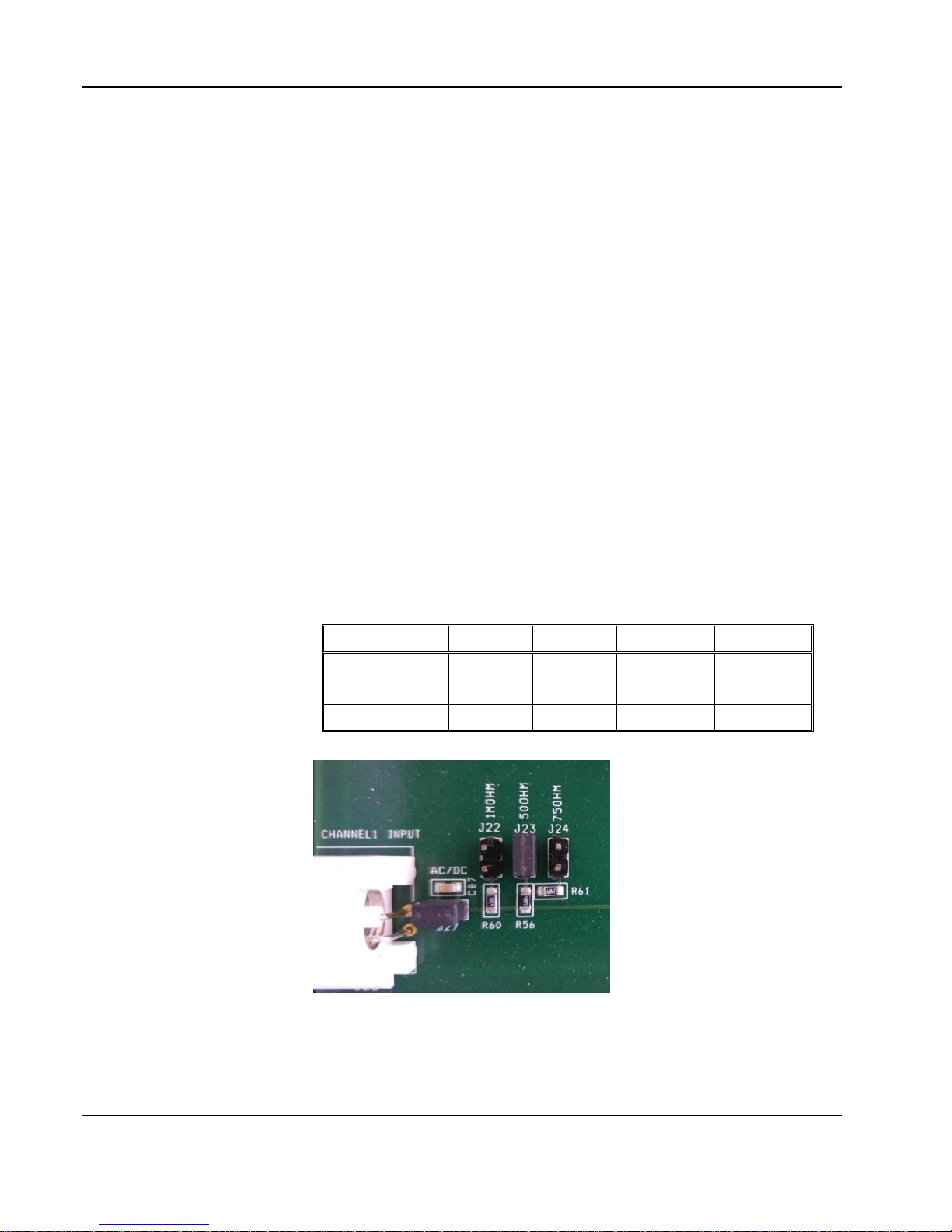
Configure the Input Impedance
Before you change the 9260 input impedance settings, identify first
the jumper location for all of the inputs. Figure 2-1 shows an example
of the channel 1 input impedance jumpers. Place the jumpers as
required according to the following table:
Table 2-1, Input Impedance Jumpers
Impedance
CH1
CH2
Aux CH1
Aux CH2
50Ω
J23
J5
J29
J14
75Ω
J24
J11
J28
J13
1MΩ
J22
J6
J30
J15
Figure 2-1, Field Modification of Channel 1 Input Impedance
2-6 Portrayal
Page 23
User Manual 9260
Configure Input/Output Coupling
The default input/output coupling is DC. Before you change the 9260
input/output coupling settings, identify first the jumper location for all
of the inputs and outputs. When the jumpers are on the links, the path
is DC coupled. Remove the jumpers from the link to modify the
settings to AC. Place or remove the jumpers as required according to
table 2-3 and 2-4.
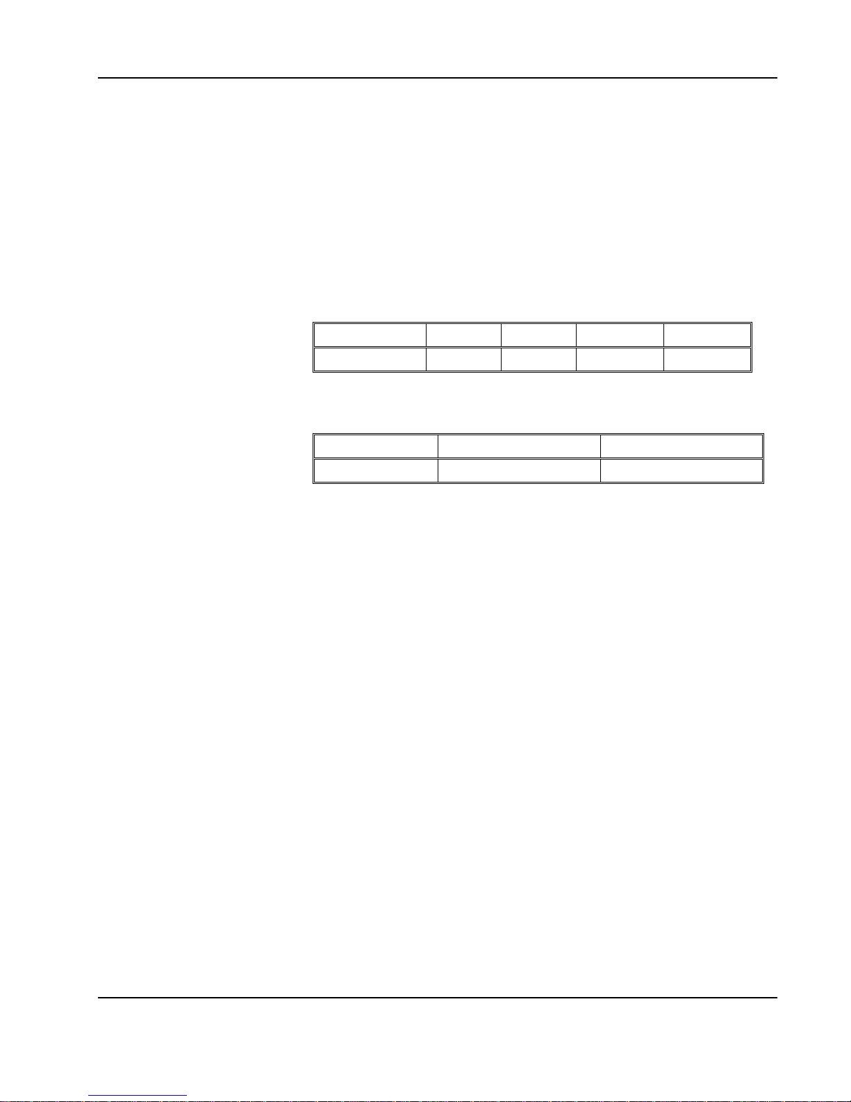
Table 2-2, Input coupling Jumpers
Input
CH1
CH2
Aux CH1
Aux CH2
Link
J27
J4
J31
J16
Table 2-3, Output coupling Jumpers
Impedance
CH1
CH2
Link
J19
J8
Configure Single-ended or Differential Outputs
The default configuration is single-ended. If you order the amplifier
with differential outputs, channel 2 input is disabled and channel 1
output is amplified and routed differentially to both channels 1 and 2.
Channel 1 outputs the normal signal and channel 2 outputs the
inverted phase signal.
The rear panel, as shown in Figure 1-2 has a push-push switch.
Pressing the switch once, will activate the differential mode and will
cause a light on the rear panel to illuminate. Pressing the switch again
will disable the differential mode and allow each amplifier to operate
separately.
Portrayal 2-7
Page 24

User Manual 9260
This page was intentionally left blank
2-8 Portrayal
Page 25
Chapter 3
What’s in This
Chapter
This chapter provides maintenance and service information,
performance tests, and the procedures necessary to adjust and
troubleshoot the Model 9260 Universal Waveform Generator.
WARNING
The procedures described in this section are for use only by qualified service personnel. Many of the steps covered in this section may expose the individual to potentially lethal voltages that could result in personal injury
or death if normal safety precautions are not observed.
CAUTION
ALWAYS PERFORM DISASSEMBLY, REPAIR AND
CLEANING AT A STATIC SAFE WORKSTATION.
Disassembly
Instructions
If it is necessary to troubleshoot the instrument or replace a
component, use the following procedure to remove the side panels:
1. Using a Phillips head screwdriver, remove the screws from the
top and bottom covers.
2. Carefully lift the top cover from its back end and slide the cover to the rear to clear the front panel spring latch. Do the same
for the bottom. After removing the covers from the instrument,
access the component side for calibration and checks, and the
solder side when replacing components.
3. When replacing the top and bottom covers, reverse the above
procedure.
RISK OF ELECTRICAL SHOCK
DO NOT OPEN
CAUTION
CAUTION
SENSITIVE ELECTRONIC DEVICES
DO NOT SHIP OR STORE NEAR
STRONG ELECTROSTATIC,
ELECTROMAGNETIC, MAGNETIC OR
RADIOACTIVE FIELDS
MAINTENANCE, PERFORMANCE CHECKS and
ADJUSTMENTS
Page 26

User Manual 9260
Special Handling
of Static Sensitive
Devices
CMOS devices are designed to operate at very high impedance levels
for low power consumption. As a result, any normal static charge that
builds up on your person or clothing may be sufficient to destroy
these devices if they are not handled properly. When handling such
devices, use the precautions described below to avoid damaging
them:
1. CMOS IC’s should be transported and handled only in con-
tainers specially designed to prevent static build-up. Typically,
these parts are received in static-protected containers of plastic or foam. Keep these devices in their original containers until ready for installation.
2. Ground yourself with a suitable wrist strap. Remove the devices from the protective containers only at a properly
grounded workstation.
3. Remove a device by grasping the body; do not touch the
pins.
4. Any printed circuit board into which the device is to be inserted must also be grounded to the bench or table.
5. Use only anti-static type solder sucker.
6. Use only grounded soldering irons.
Once the device is installed on the PC board, the device is
adequately protected and normal handling may resume.
3-2 MAINTENANCE, PERFORMANCE CHECKS and ADJUSTMENTS
Page 27

User Manual 9260
Cleaning
The Model 9260 should be cleaned as often as operating conditions
require. To clean the instrument, use the following procedure:
1. Thoroughly clean the inside and outside of the instrument.
2. When cleaning inaccessible areas, remove dust with lowpressure compressed air or a vacuum cleaner.
3. Use alcohol applied with a cleaning brush to remove accumulation of dirt or grease from connector contacts and component terminals.
4. Clean the exterior of the instrument and the front panel with a
mild detergent mixed with water, applying the solution with a
soft, lint-free cloth.
Repair and
Replacement
Repair and replacement of electrical and mechanical parts must be
accomplished with great care. Printed circuit boards can become
warped, cracked or burnt from excessive heat or mechanical stress.
The following repair techniques are suggested to avoid inadvertent
destruction or degradation of parts and assemblies:
1. Use a 60/40 solder and temperature-controlled 35 - 40 watt
pencil-type soldering iron on the circuit board. The tip of the
iron should be clean and properly tinned for best heat transfer
to the solder joint. A higher wattage soldering iron may separate the circuit from the base material.
2. Keep the soldering iron in contact with the PC board for a
minimum time to avoid damage to the components or printed
conductors.
3. To de-solder components, use a commercial "solder sucker"
or a solder-removing SOLDER - WICK, size 3.
4. Always replace a component with an exact duplicate as specified in the parts list.
MAINTENANCE, PERFORMANCE CHECKS and ADJUSTMENTS 3-3
Page 28

User Manual 9260
Performance
Checks
The performance of the 9260 should be checked to verify proper
operation of the instrument and should normally be used:
1. As a part of the incoming inspection of the instrument specifications;
2. As part of the troubleshooting procedure;
3. After any repair or adjustment before returning the instrument
to regular service.
Environmental
Conditions
Tests should be performed under laboratory conditions having an
ambient temperature of 25C, 5C and at relative humidity of less
than 80%. If the instrument has been subjected to conditions outside
these ranges, allow at least one additional hour for the instrument to
stabilize before beginning the adjustment procedure.
Warm-up Period
Most instruments are subject to small amount of drifts when first
turned on. To ensure accuracy, turn on the power to the Model 9260
and allow it to warm-up for at least 10 minutes before beginning the
performance test procedure.
9260 Configuration
for the Tests
The 9260 is tested using the factory recommended configuration. The
instrument should be configured as follows for the performance tests:
Input impedance = 50; Output impedance = 50; Gain = 10;
Coupling = DC. Other configurations can be tested but slight
degradation of performance should be considered, as specified in
Appendix A
Recommended
Test Equipment
Recommended test equipment for troubleshooting, calibration and
performance checking is listed below. Test instruments other than
those listed may be used only if their specifications equal or exceed
the required characteristics.
Equipment
Model No.
Manufacturer
Oscilloscope
DSO9404A
Keysight
Digital Multimeter
2000
Keithley
Spectrum Analyzer
FSP3
R&S
Pulse Generator
PM8571A
Tabor Electronics
Table 3-1, Recommended Test Equipment
3-4 MAINTENANCE, PERFORMANCE CHECKS and ADJUSTMENTS
Page 29
User Manual 9260
Performance Check
Procedures
Use the following procedures to check the Model 9260 against the
specifications. A complete set of specifications is listed in Appendix
A. The following paragraphs show how to set up the instrument for
the test, what the specifications for the tested function are, and what
acceptable limits for the test are. If the instrument fails to perform
within the specified limits, the instrument must be calibrated or tested
to find the source of the problem.
Gain Accuracy
Tests
Equipment: DMM, PM8571A Pulse Waveform Generator
Preparation:
1. Configure the DMM as follows:
Function: ACV
Range: As required by the test
2. Connect the 9260 input to the PM8571A output
3. Connect 9260 Channel output to the DMM input via 50Ω/2W
Termination
4. Configure the PM8571A as follows:
Frequency: 10 kHz
Outputs: On
Amplitude: As required for the test
Test Procedure
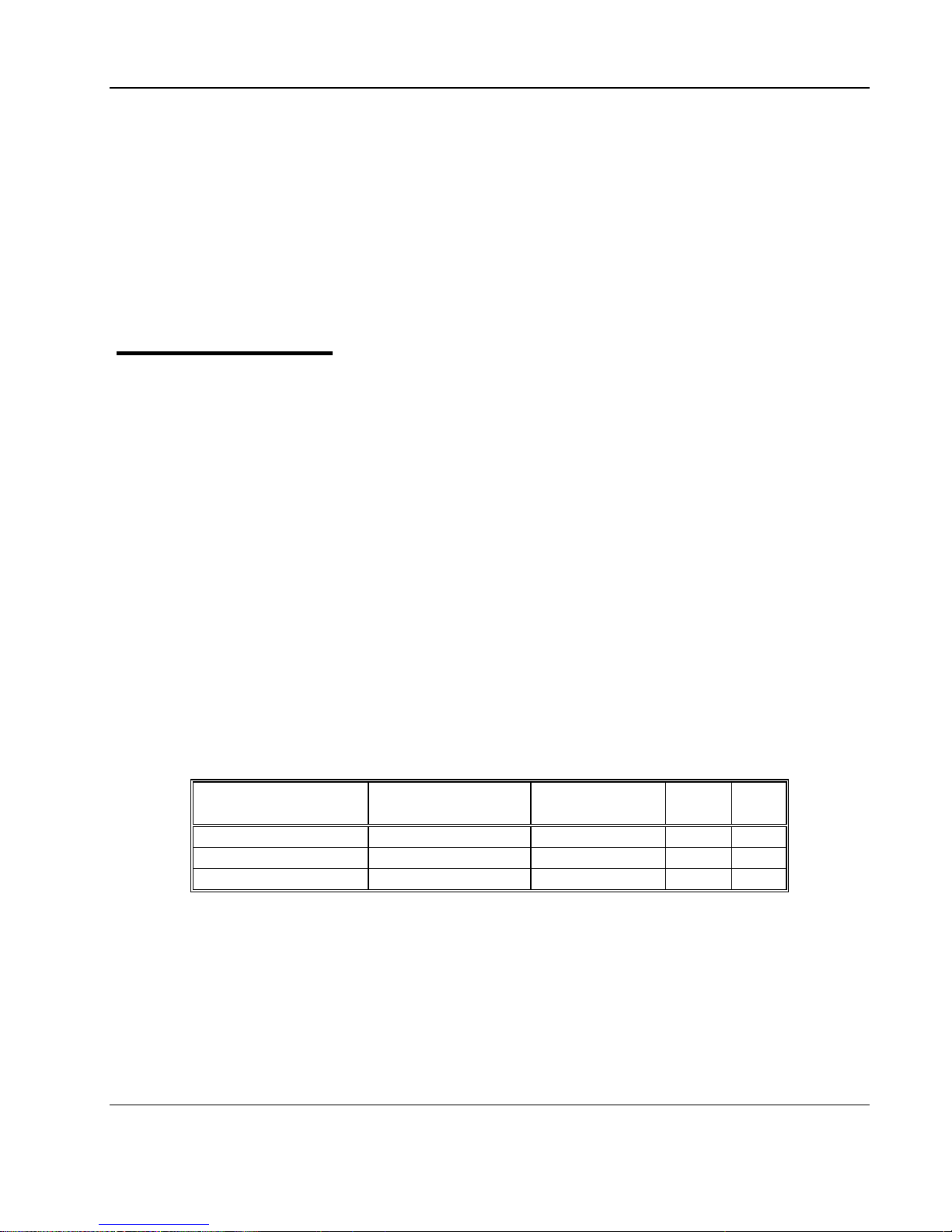
1. Perform Gain Accuracy tests using Table 3-2
PM8571A
Amplitude Setting
Error Limits
DMM Reading
Pass
Fail
0.5 Vp-p
1.767 V, ±71 mV
1 Vp-p
3.535 V, ±141 mV
2 Vp-p
7.071 V, ±282 mV
Table 3-2, Gain Accuracy Tests
MAINTENANCE, PERFORMANCE CHECKS and ADJUSTMENTS 3-5
Page 30
User Manual 9260
Amplifier
Bandwidth
Amplifier bandwidth checks the bandwidth of the output.
Amplitude Accuracy
Equipment: Oscilloscope, PM8571A Pulse Waveform
Generator
Preparation:
1. Configure the Oscilloscope as follows:
Time Base: 200 μs/div
Amplitude: 5 V/div
2. Connect the 9260 input to the PM8571A output
3. Connect 9260 Channel outputs to the Oscilloscope input
via 50Ω/2W Termination
4. Configure the PM8571A as follows:
Amplitude: 2 V
Outputs: On
Frequency: As specified in Table 3-3
Test Procedure
1. Using the variable vertical adjustment on the oscilloscope, adjust the vertical trace to show exactly 6 vertical
divisions
2. Perform bandwidth tests using Table 3-3
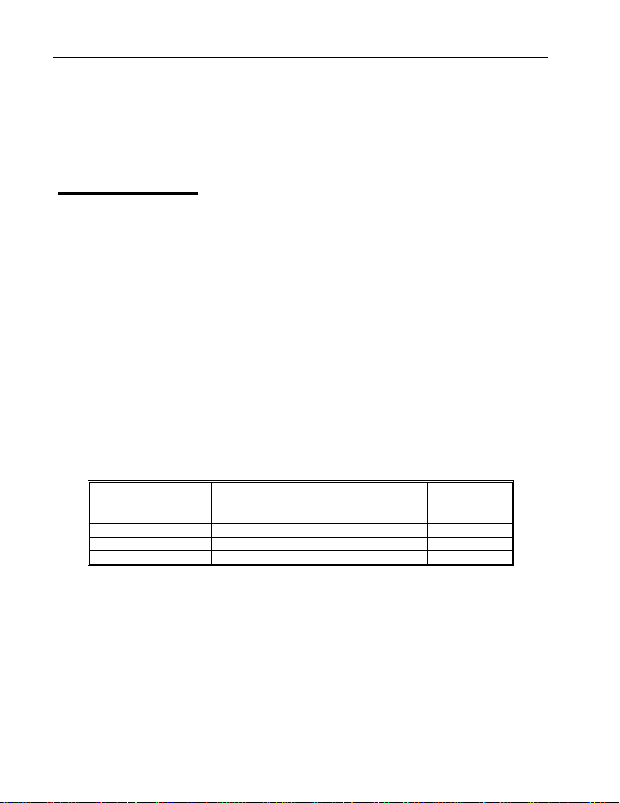
PM8571A Frequency
Oscilloscope
Setting
Error Limits
Reading
Pass
Fail
1 MHz
6 Divisions
10 MHz
6 ±0.5 Divisions
20 MHz
6 ±1 Divisions
45 MHz
6 ±1.8 Divisions
Table 3-3, Output Bandwidth Tests
3-6 MAINTENANCE, PERFORMANCE CHECKS and ADJUSTMENTS
Page 31
User Manual 9260
Amplifier Pulse
Response
Amplifier pulse response checks the aberrations, which include rise
and fall times, overshoot and undershoot.
Pulse Response
Checks
Equipment: Oscilloscope, PM8571A Pulse Waveform Generator
Preparation:
1. Configure the Oscilloscope follows:
Setup: As required for the test
2. Connect the 9260 input to the PM8571A output
3. Connect 9260 outputs to the oscilloscope input via 50Ω/2W
Termination
Configure the PM8571A as follows:
Frequency: 1 MHz
Waveform: Square wave
Amplitude: 2 V
Outputs: On
Test Procedure
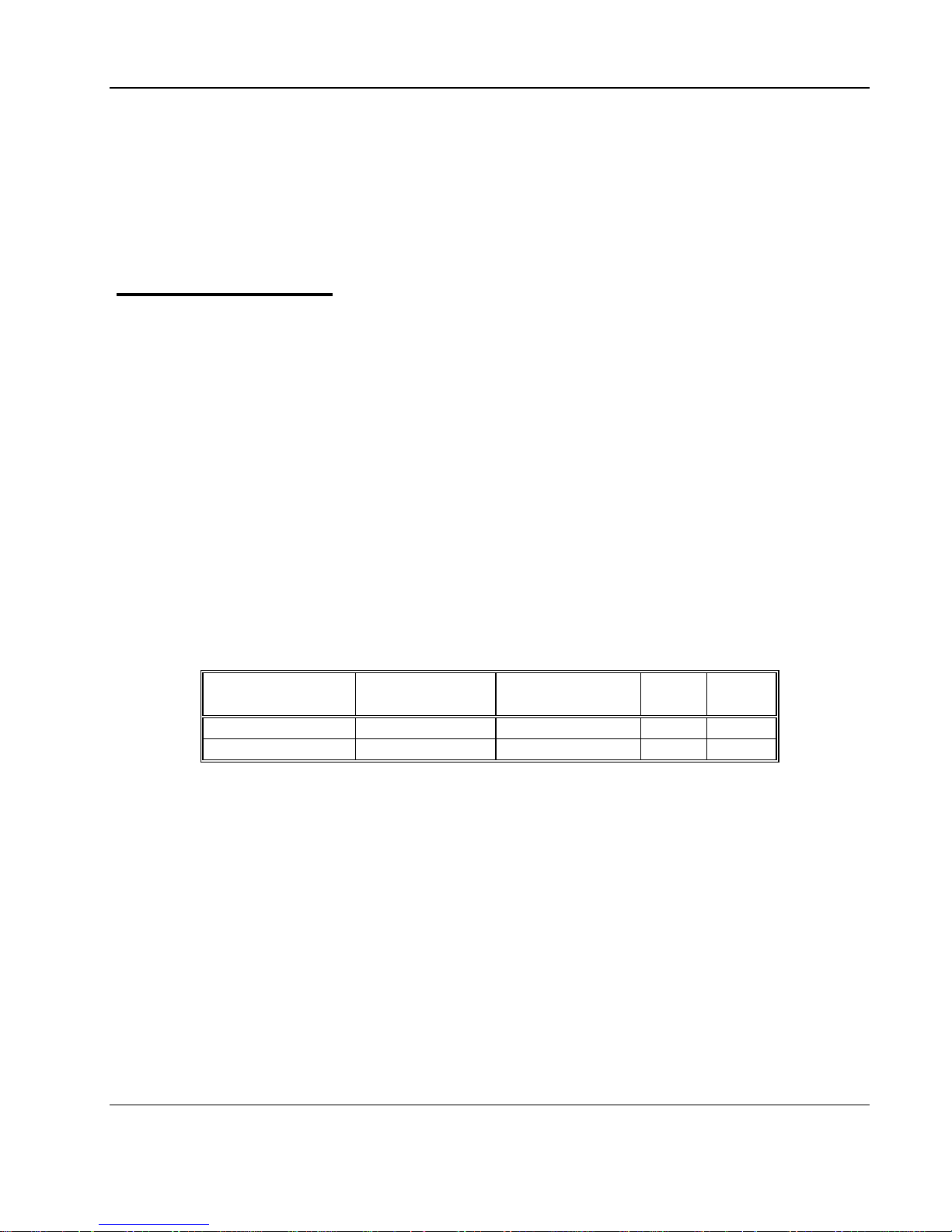
1. Perform Square Wave Characteristics tests using Table 3-4.
Parameter
Oscilloscope
Reading
Tested
Error Limits
Pass
Fail
Rise/Fall Time
<10 ns
Over/undershoot
<10%
Table 3-4, Square Wave Characteristics
MAINTENANCE, PERFORMANCE CHECKS and ADJUSTMENTS 3-7
Page 32

User Manual 9260
Auxiliary Inputs
Auxiliary inputs checks the functionality of the rear panel Inputs,
which include Auxiliary Input and Auxiliary Offset.
Auxiliary Offset
Checks
Equipment: Oscilloscope, PM8571A Pulse Waveform Generator,
Function Generator
Preparation:
1. Configure the Oscilloscope as follows:
Time Base: 1 μs/div
Amplitude: 5 V/div
Measurement: DC offset
2. Connect the 9260 input to the PM8571A output
3. Connect 9260 Channel outputs to the Oscilloscope input via
50Ω/2W Termination
4. Configure the PM8571A as follows:
Amplitude: 1 V
Outputs: On
Frequency: 1MHz
5. Connect the Function Generator output to the rear panel Input
6. Configure the Function Generator as follows:
Wave shape: DC
Output: On
DC Amplitude: As specified in Table 3-5
Test Procedure
1. Perform Offset tests using Table 3-5.
Function Generator
Oscilloscope
Setting
Error Limits
DC offset Reading
Pass
Fail
-1V
-1V±0.1V
-0.5V
-0.5V±0.05V
0.5V
0.5V±0.05V
+1V
1V±0.1V
Table 3-5, Auxiliary Offset Characteristics
3-8 MAINTENANCE, PERFORMANCE CHECKS and ADJUSTMENTS
Page 33

User Manual 9260
Auxiliary Input
Checks
Equipment: Oscilloscope, PM8571A Pulse Waveform Generator
Preparation:
1. Configure the Oscilloscope as follows:
Time Base: 10 μs/div
Amplitude: 5 V/div
Measurement: Amplitude Vpp
2. Connect the 9260 input CH1 to the PM8571A CH1output and
9260 Auxiliary Input CH1 to the PM8571A CH2 output
3. Connect 9260 Channel outputs to the Oscilloscope input via
50Ω/2W Termination
4. Configure the PM8571A as follows:
Outputs: Coupled
Frequency: 1MHz
Amplitude CH1: 1 V
Amplitude CH2: 1 V
CH1, CH2: On
Test Procedure
1. Measure the output amplitude, should be 10Vpp±0.5V.
MAINTENANCE, PERFORMANCE CHECKS and ADJUSTMENTS 3-9
Page 34

User Manual 9260
Adjustment
Procedures
Use the following procedures to calibrate the Model 9260. The
following paragraphs show how to set up the instrument for calibration
and what the acceptable calibration limits are
NOTE
Initial factory adjustments require that the covers be removed from the instrument.
Amplifier Gain
Adjustments
The gain adjustments ensure that amplifier gain within the specified
range. Use this procedure if you suspect that the gain is an issue.
Gain Adjustments
Equipment: DMM, PM8571A AWG
Preparation:
5. Configure the DMM as follows:
Function: ACV
6. Connect the PM8571A to the DMM input
7. Configure the PM8571A as follows:
Wave Shape: Sin
Frequency: 10 kHz
Amplitude: 2Vpp
Output: On
8. Adjust the PM8571A output till DMM reading is 0.707V
9. Connect the 9260 input channel 1 to the PM8571A output
10. Connect 9260 Channel 1 output to the DMM input via 50Ω/2W
Termination
Adjustment:
Adjust RV5 till output amplitude is within 7.07 V, ±282 mV
11. Connect the 9260 input channel 2 to the PM8571A output
12. Connect 9260 Channel 1 output to the DMM input via 50Ω/2W
Termination
Adjustment:
Adjust RV3 till output amplitude is within 7.07 V, ±282 mV
3-10 MAINTENANCE, PERFORMANCE CHECKS and ADJUSTMENTS
Page 35

User Manual 9260
Pulse Response
Adjustments
The pulse response adjustments ensure that rise and fall times as
well as aberrations are within the specified range. Use this procedure
if you suspect that the pulse response is an issue.
Pulse Adjustments
Equipment: Oscilloscope, PM8571A AWG
Preparation:
1. Configure the PM8571A as follows:
Function: Standard
Waveform: Square
Frequency: 1MHz
Amplitude: 2Vpp
Output: On
2. Connect the 9260 input channel 1 to the PM8571A output
3. Connect the 9260 output channel 1 to the oscilloscope input
via 50Ω/2W Termination.
Adjustment:
Adjust C77 for best pulse response (<10ns, 10% aberrations)
4. Connect the 9260 input channel 2 to the PM8571A output
5. Connect the 9260 output channel 2 to the oscilloscope input
via 50Ω/2W Termination.
Adjustment:
Adjust C35 for best pulse response (<10ns, 10% aberrations)
MAINTENANCE, PERFORMANCE CHECKS and ADJUSTMENTS 3-11
Page 36

User Manual 9260
This Page was intentionally left blank
3-12 MAINTENANCE, PERFORMANCE CHECKS and ADJUSTMENTS
Page 37

Specifications A-1
Appendix A
Characteristics
Description
No. of Channels
2 with single-ended outputs; 1 with differential outputs, 2 Summing, 2 DC offset
Connector
Front panel BNC
Impedance
50Ω, 75Ω or 1MΩ (factory configured)
Coupling
DC or AC
Damage Level
12Vp-p (-6V to +6V peaks)
Differential Mode Accuracy
4%
Characteristics
Description
Connector
Rear panel BNC
Impedance
50Ω
Coupling
DC
Damage Level
12Vp-p (-6V to +6V peaks)
Characteristics
Description
Connector
Rear panel BNC
Impedance
10kΩ
Coupling
DC
Damage Level
±2V
Accuracy
7%
Characteristics
Description
No. of Channels
2
Coupling
DC or AC coupled
Connector
Front panel BNC
Gain (load 50Ω)
X10, fixed (Can be ordered from factory with different gain setting. Bandwidth may
change with different gain configuration)
Polarity
Normal
Impedance
0Ω
Protection
Short Circuit to Case Ground & Thermal protection
Amplitude
34Vpp into 50Ω
Max. Output Current
1A
Rise/Fall Time
<10ns (typ.)
Aberration
<10%
9260 SPECIFICATIONS
Main Input Characteristics
Input Auxiliary Characteristics
Offset Auxiliary Input Characteristics
Output Characteristics
Page 38

Specifications A-2
Frequency
Characteristics
Description
Frequency Range
DC to 45MHz
Bandwidth (-3dB) 50Ω Load
45MHz (typ.)
Harmonics Distortion (typ.)
10Vpp
25Vpp
1MHz
<-65dBc
<-54dBc
10MHz
<-50dBc
<-45dBc
30MHz
<-38dBc
<-30dBc
Characteristics
Description
Power Requirements
85V to 265V, 47-63Hz, <25W
Signal Ground
Grounded to case ground or Floating
EMC Certification
CE marked
Characteristics
Description
Physical Size
2U, half-rack size
Weight
Approximately 7Lbs
Characteristics
Description
Temperature
Operating
0C to 50C
Storage
-40C to 70C
Humidity
85% RH, non-condensing
Mechanical, Environmental and Maintenance Specifications
Power supply
Mechanical
Environmental
 Loading...