

Page 1

User Manual
Model 5251
250 MS/s PXIbus
Arbitrary Waveform Generator
Publication No. 100520
Copyright 2002 by Tabor Electronics. All rights reserved. This book or parts thereof may not be reproduced
in any form without written permission of the publisher.
Tabor Electronics Ltd.
9 Hatasia Street, Nesher, Israel 20302
TEL: (972) 4 821 3393, FAX: (972) 4 821 3388
[www.taborelec.com]
PUBLICATION DATE: May 20, 2010
REVISION: 1.0
Page 2

WARRANTY STATEMENT
Products sold by Tabor Electronics are warranted to be free from defects in workmanship or materials. Tabor
Electronics will, at its option, either repair or replace any hardware products, which prove to be defective
during the warranty period. You are a valued customer. Our mission is to make any necessary repairs in a
reliable and timely manner.
Duration of Warranty
The warranty period for this Tabor Electronics hardware is one year, except software and firmware products
designed for use with Tabor Electronics Hardware is warranted not to fail to execute its programming
instructions due to defect in materials or workmanship for a period of ninety (90) days from the date of delivery
to the initial end user.
Return of Product
Authorization is required from Tabor Electronics before you send your product for service or calibration. Call
your nearest Tabor Electronics support facility. A list is located on the last page of this manual. If you are
unsure where to call, contact Tabor Electronics Customer Support Department.
Limitation of Warranty
Tabor Electronics shall be released from all obligations under this warranty in the event repairs or
modifications are made by persons other than authorized Tabor Electronics service personnel or without the
written consent of Tabor Electronics.
Tabor Electronics expressly disclaims any liability to its customers, dealers and representatives and to users
of its product, and to any other person or persons, for special or consequential damages of any kind and from
any cause whatsoever arising out of or in any way connected with the manufacture, sale, handling, repair,
maintenance, replacement or use of said products.
Representations and warranties made by any person including dealers and representatives of Tabor
Electronics, which are inconsistent or in conflict with the terms of this warranty (including but not limited to the
limitations of the liability of Tabor Electronics as set forth above), shall not be binding upon Tabor Electronics
unless reduced to writing and approved by an officer of Tabor Electronics
Except as stated above, Tabor Electronics makes no warranty, express or implied (either in fact or by
operation of law), statutory or otherwise; and except to the extent stated above, Tabor Electronics shall have
no liability under any warranty, express or implied (either in fact or by operation of law), statutory or otherwise.
PROPRIETARY NOTICE
This document and the technical data herein disclosed, are proprietary to Tabor Electronics, and shall not, without
express written permission of Tabor Electronics, be used, in whole or in part to solicit quotations from a competitive
source or used for manufacture by anyone other than Tabor Electronics. The information herein has been developed at
private expense, and may only be used for operation and maintenance reference purposes or for purposes of
engineering evaluation and incorporation into technical specifications and other docum ents, which specify procurement
of products from Tabor Electronics.
Page 3

DECLARATION OF CONFORMITY
We: Tabor Electronics Ltd.
9 Hatasia Street, Tel Hanan
ISRAEL 36888
declare, that the 250MS/s Single Channel Arbitrary Waveform Generator
Model 5251
meet the intent of the requirements of the Electro Magnetic Compatibility 89/336/EEC as
amended by 92/31/EEC, 93/68/EEC, 92/263/EEC and 93/97/EEC and the Low Voltage
Directive 73/23/EEC amended by 93/68/EEC. Compliance was demonstrated to the
following specifications as listed in the official Journal of the European Communities:
Safety:
IEC/EN 61010-1 2nd Edition: 2001+ C1, C2
EMC:
EN55022:2001 Class A Radiated and Conducted Emission
IEC61000-3-2:2001(Am1) Harmonics
IEC61000-3-3:2002(Am1) Flickers
IEC61000-4-2:2001(Am1+Am2) ESD : Contact Discharge ±4Kv
Air Discharge ±8Kv
IEC61000-4-3:2002(Am1) Radiated immunity - 3V/m (80MHz-1000MHz)
IEC61000-4-4:2001 (Am2) Electrical Fast Transient and Burst ±1.0kV, 5KHz
IEC61000-4-5:2001 (Am1) Surges DM ±1.0kV CM ±2.0Kv
IEC61000-4-6:2003 Current injection immunity - 3Vrms
IEC61000-4-8:2001 Magnetic field 1Amper
IEC61000-4-11:2001 Voltage dips and variation
The tests were performed on a typical configuration.
Page 4

1
Getting Started .................................................................................................................. 1-1
What’s In This Chapter ....................................................................................................... 1-3
Conventions Used in this Manual ................................................................ ....................... 1-3
Introduction ........................................................................................................................ 1-3
TE5251 Feature Highlights ................................................................................................. 1-4
ArbConnection Feature Highlights ...................................................................................... 1-5
Functional Description ........................................................................................................ 1-7
Supplied Accessories ......................................................................................................... 1-8
Specifications ..................................................................................................................... 1-8
Functional Description ........................................................................................................ 1-9
Front Panel Connectors .................................................................................................. 1-9
Output ......................................................................................................................... 1-9
SYNC Output .............................................................................................................. 1-9
TRIG IN ...................................................................................................................... 1-9
SCLK IN ..................................................................................................................... 1-10
REF IN ........................................................................................................................ 1-10
Run Modes ..................................................................................................................... 1-11
Continuous Mode ....................................................................................................... 1-11
Triggered Mode .......................................................................................................... 1-11
Gated Mode ................................................................................................................ 1-11
Burst Mode ................................................................................................................. 1-11
Output Type .................................................................................................................... 1-12
Standard (FIXED) Waveforms .................................................................................... 1-12
Table of Contents
Chapter Title Page
i
Page 5

TE5251
Arbitrary (User) Waveforms ........................................................................................ 1-12
Sequenced Waveforms .............................................................................................. 1-13
Modulated Waveforms ................................................................................................ 1-14
Sweep ..................................................................................................................... 1-14
FM ........................................................................................................................... 1-15
AM ........................................................................................................................... 1-15
Frequency Hop ........................................................................................................ 1-15
FSK ......................................................................................................................... 1-15
PSK ......................................................................................................................... 1-15
ASK ......................................................................................................................... 1-16
3D ........................................................................................................................... 1-16
Pulse Waveforms........................................................................................................ 1-16
Half Cycle Waveforms ................................................................................................ 1-16
Counter/Timer ............................................................................................................. 1-16
Output State ....................................................................................................................... 1-17
Filters ................................................................................................................................. 1-17
Programming The 5251 ..................................................................................................... 1-17
2
Configuring the Instrument ............................................................................................. 2-1
Installation Overview .......................................................................................................... 2-3
Unpacking and Initial Inspection ...................................................................................... 2-3
Safety Precautions .......................................................................................................... 2-3
Operating ........................................................................................................................... 2-4
Environment ....................................................................................................................... 2-4
Power Requirements .......................................................................................................... 2-4
Grounding Requirements ................................................................................................... 2-4
Calibration .......................................................................................................................... 2-5
Abnormal Conditions .......................................................................................................... 2-5
Long Term Storage or Repackaging For Shipment ......................................................... 2-5
Preparation For Use ........................................................................................................ 2-6
Removing the Instrument from the Bag .............................................................................. 2-6
Installation .......................................................................................................................... 2-6
Installing Instrument Drivers ............................................................................................... 2-7
Installing Software Utilities ................................................................................................. 2-12
Installing IVI Drivers and ArbConnection ............................................................................ 2-13
User Manual
ii
Page 6

3
ArbConnection© ............................................................................................................. 3-1
What’s in This Chapter? ..................................................................................................... 3-3
Introduction to ArbConnection ............................................................................................ 3-3
Installing ArbConnection .................................................................................................... 3-3
Quitting ArbConnection..................................................................................................3-4
For the New and Advanced Users .................................................................................3-4
Conventions Used in This Manual .................................................................................3-4
The Opening Screen .......................................................................................................... 3-5
ArbConnection Features .................................................................................................... 3-6
The Control Panels ............................................................................................................ 3-7
The Operation Panels ....................................................................................................3-8
Main ...........................................................................................................................3-9
Standard .................................................................................................................. 3-11
Arbitrary/Sequence ................................................................................................. 3-12
Using the Memory Partition Table .......................................................................... 3-14
Using the Waveform Studio .................................................................................... 3-15
Trigger ..................................................................................................................... 3-19
The Modulation Panels ............................................................................................... 3-21
FM ........................................................................................................................... 3-21
AM ........................................................................................................................... 3-22
Sweep ..................................................................................................................... 3-23
ASK/FSK/PSK ......................................................................................................... 3-24
Frequency Hop ........................................................................................................ 3-26
The Auxiliary Panels ................................................................................................... 3-28
Counter/Timer ......................................................................................................... 3-28
Pulse Generator ...................................................................................................... 3-30
Half Cycle ................................................................................................................ 3-31
The System Panels ..................................................................................................... 3-32
General/Filters ......................................................................................................... 3-32
Calibration ............................................................................................................... 3-33
The Composers Panels .............................................................................................. 3-34
The Wave Composer .............................................................................................. 3-35
The Toolbar ................................................................................................................ 3-41
The Waveform Screen ................................................................................................ 3-42
Generating Waveforms Using the Equation Editor ........................................................... 3-43
Writing Equations ........................................................................................................ 3-45
Equation Convention .................................................................................................. 3-46
Contents (continued)
iii
Page 7

TE5251
Typing Equations ........................................................................................................ 3-47
Equation Samples ....................................................................................................... 3-48
Combining Waveforms ............................................................................................... 3-52
The Pulse Composer .............................................................................................. 3-53
The FM Composer .................................................................................................. 3-71
The 3D Composer ................................................................................................... 3-75
The Command Editor ....................................................................................................... 3-80
Logging SCPI Commands ................................................................................................ 3-81
4
Remote Programming Reference .................................................................................... 4-1
What’s in This Chapter ..................................................................................................... 4-3
What is Required ............................................................................................................. 4-3
Introduction to SCPI ......................................................................................................... 4-3
Command Format .......................................................................................................... 4-4
Command Separator ..................................................................................................... 4-4
The MIN and MAX
Parameters ..................................................................................... 4-5
Querying Parameter Setting .......................................................................................... 4-5
Query Response Format ............................................................................................... 4-5
SCPI Command Terminator .......................................................................................... 4-5
IEEE-STD-488.2 Common Commands ......................................................................... 4-5
SCPI Parameter Type .................................................................................................... 4-6
Numeric Parameters .................................................................................................. 4-6
Discrete Parameters .................................................................................................. 4-6
Boolean Parameters .................................................................................................. 4-6
Arbitrary Block Parameters ........................................................................................ 4-6
Binary Block Parameters ........................................................................................... 4-7
SCPI Syntax and Styles ................................................................................................... 4-7
Instrument Control Commands ........................................................................................ 4-14
Standard Waveforms Control Commands ........................................................................ 4-21
Arbitrary Waveforms Control Commands ......................................................................... 4-28
Sequenced Waveforms Control Commands .................................................................... 4-34
Modulated Waveforms Control Commands ...................................................................... 4-41
FM Modulation Programming ........................................................................................ 4-45
AM modulation Programming ........................................................................................ 4-49
Sweep Modulation Programming .................................................................................. 4-51
FSK Modulation Programming ...................................................................................... 4-54
ASK Modulation Programming ...................................................................................... 4-56
Frequency Hopping Modulation Programming .............................................................. 4-57
User Manual
iv
Page 8

3D Modulation Programming ......................................................................................... 4-61
PSK Modulation Programming ...................................................................................... 4-63
Run Mode Commands ................................................................................................ ..... 4-66
Auxiliary Commands ........................................................................................................ 4-72
Digital Pulse Programming ............................................................................................ 4-73
Counter/Timer Programming ......................................................................................... 4-78
Half Cycle Programming ................................................................................................ 4-81
System Commands ....................................................................................................... 4-83
IEEE-STD-488.2 Common Commands and Queries ....................................................... 4-85
Error Messages ............................................................................................................... 4-85
5
Performance Checks ........................................................................................................ 5-1
What’s in This Chapter ........................................................................................................ 5-3
Performance Checks .......................................................................................................... 5-3
Environmental Conditions ................................................................................................... 5-3
Warm-up Period .................................................................................................................. 5-4
Initial Instrument Setting ...................................................................................................... 5-4
Recommended Test Equipment .......................................................................................... 5-4
Test Procedures.................................................................................................................. 5-4
Frequency Accuracy ........................................................................................................ 5-5
Frequency Accuracy, Internal Reference ......................................................................... 5-5
Frequency Accuracy, External 10MHz Reference ............................................................... 5-5
Amplitude Accuracy ............................................................................................................ 5-6
Amplitude Accuracy, DAC Output .................................................................................... 5-6
Amplitude Accuracy, DDS Output .................................................................................... 5-6
Offset Accuracy................................................................................................................... 5-7
Offset Accuracy, DAC Output .......................................................................................... 5-7
Offset Accuracy, DDS Output .......................................................................................... 5-8
Squarewave Characteristics ............................................................................................... 5-9
Squarewave Checks ....................................................................................................... 5-9
Sinewave Characteristics .................................................................................................... 5-9
Sinewave Distortion, DAC Output .................................................................................... 5-9
Sinewave Spectral Purity, DAC Output ............................................................................ 5-10
Sinewave Spectral Purity, DDS Output ............................................................................ 5-11
Sinewave Flatness, DAC Output ..................................................................................... 5-11
Sinewave Flatness, DDS Output ..................................................................................... 5-12
Trigger operation Characteristics ........................................................................................ 5-12
Trigger, Gate, and Burst Characteristics .......................................................................... 5-13
Mixed Trigger Advance Test ............................................................................................ 5-13
Contents (continued)
v
Page 9

TE5251
Delayed Trigger Characteristics ................................ ...................................................... 5-14
Re-trigger Characteristics ................................................................................................ 5-15
Trigger Slope .................................................................................................................. 5-16
Trigger Level ................................................................................................................... 5-16
Sequence operation ............................................................................................................ 5-17
Automatic Advance ......................................................................................................... 5-17
Step Advance .................................................................................................................. 5-18
Single Advance ............................................................................................................... 5-19
SYNC Output Operation ..................................................................................................... 5-19
SYNC Qualifier - Bit ........................................................................................................ 5-20
SYNC Qualifier - LCOM .................................................................................................. 5-20
Arbitrary Waveform Memory Operation ............................................................................... 5-21
Waveform memory .......................................................................................................... 5-21
Modulated Waveforms Operation ....................................................................................... 5-21
FM - Standard Waveforms .............................................................................................. 5-21
Triggered FM - Standard Waveforms .............................................................................. 5-22
FM Burst - Standard Waveforms ..................................................................................... 5-23
Gated FM - Standard Waveforms .................................................................................... 5-24
Re-triggered FM Bursts - Standard Waveforms ............................................................... 5-25
FM - Arbitrary Waveforms ............................................................................................... 5-26
AM .................................................................................................................................. 5-26
FSK ................................................................................................................................. 5-27
PSK ................................................................................................................................. 5-28
ASK ................................................................................................................................. 5-28
Variable Dwell Time Frequency Hops ............................................................................. 5-29
Fix Dwell Time Frequency Hops ...................................................................................... 5-30
Sweep ............................................................................................................................. 5-31
Auxiliary Counter/Timer Operation ...................................................................................... 5-32
Frequency ....................................................................................................................... 5-32
Period, Period Averaged ................................................................ ................................. 5-33
Pulse Width ..................................................................................................................... 5-34
Totalize, Gated ................................................................................................................ 5-34
Totalize, Infinite ................................................................................................ ............... 5-35
6
Adjustments and Firmware Update ................................................................................. 6-1
What’s in This Chapter........................................................................................................ 6-3
Performance Checks .......................................................................................................... 6-3
Environmental Conditions ................................................................................................... 6-3
Warm-up Period.................................................................................................................. 6-3
Recommended Test Equipment .......................................................................................... 6-4
Adjustment Procedures....................................................................................................... 6-4
User Manual
vi
Page 10

Reference Oscillators Adjustments ....................................................................................... 6-7
(Setup 50MHz)................................................................................................................... 6-7
Setup TCXO....................................................................................................................... 6-7
Base Line Offset Adjustments............................................................................................... 6-8
Setup 1............................................................................................................................... 6-8
Setup 2............................................................................................................................... 6-8
Setup 3............................................................................................................................... 6-9
Setup 4............................................................................................................................... 6-9
Setup 5............................................................................................................................... 6-9
Setup 6............................................................................................................................. 6-10
Offset Adjustments.............................................................................................................. 6-10
Setup 7............................................................................................................................. 6-10
Setup 8............................................................................................................................. 6-11
Setup 9............................................................................................................................. 6-11
Setup 10........................................................................................................................... 6-11
Setup 11........................................................................................................................... 6-12
Setup 12........................................................................................................................... 6-12
Setup 13........................................................................................................................... 6-13
Setup 14........................................................................................................................... 6-13
Amplitude Adjustments........................................................................................................ 6-13
Setup 15........................................................................................................................... 6-14
Setup 16........................................................................................................................... 6-14
Setup 17........................................................................................................................... 6-14
Setup 18........................................................................................................................... 6-15
Setup 19........................................................................................................................... 6-15
Setup 20........................................................................................................................... 6-16
Amplitude Adjustments-Modulation..................................................................................... 6-16
Setup 21........................................................................................................................... 6-16
Setup 22........................................................................................................................... 6-17
Setup 23........................................................................................................................... 6-17
Setup 24........................................................................................................................... 6-17
Setup 25........................................................................................................................... 6-18
Setup 26........................................................................................................................... 6-18
Pulse Response Adjustments.............................................................................................. 6-19
(Setup 27)........................................................................................................................ 6-19
(Setup 28)........................................................................................................................ 6-19
Flatness Adjustments.......................................................................................................... 6-20
Setup 29........................................................................................................................... 6-20
Setup 30........................................................................................................................... 6-20
Setup 31........................................................................................................................... 6-20
Setup 32........................................................................................................................... 6-21
Setup 33........................................................................................................................... 6-21
Contents (continued)
vii
Page 11

TE5251
Setup 34 ............................................................................................................................. 6-22
Setup 35 ............................................................................................................................. 6-22
Setup 36 ............................................................................................................................. 6-22
Setup 37 ............................................................................................................................. 6-23
Setup 38 ............................................................................................................................. 6-23
Setup 39 ............................................................................................................................. 6-24
Setup 40 ............................................................................................................................. 6-24
Setup 41 ............................................................................................................................. 6-24
Setup 42 ............................................................................................................................. 6-25
Setup 43 ............................................................................................................................. 6-25
Setup 44 ............................................................................................................................. 6-25
Setup 45 ............................................................................................................................. 6-26
Setup 46 ............................................................................................................................. 6-26
Setup 47 ............................................................................................................................. 6-27
Updating the 5251 Firmware ................................................................................................. 6-28
Appendices
A
Specifications ................................................................................................................... A-1
User Manual
viii
Page 12

4 1, Model 5251 SCPI Commands List Summary ....................................................................... 4-8
4 2, Instrument Control Commands Summary ........................................................................... 4-14
4 3, Instrument Control Commands Summary ........................................................................... 4-21
4 4, Arbitrary Waveforms Commands Summary ....................................................................... 4-29
4 5, Sequence Control Commands ............................................................................................ 4-36
4 6, Modulated Waveforms Commands ..................................................................................... 4-42
4 7, Run Mode Commands ........................................................................................................ 4-67
4 8, Auxiliary Commands ........................................................................................................... 4-72
4 9, System Commands Summary ............................................................................................ 4-83
5-1, Recommended Test Equipment ........................................................................................... 5-3
5-2, Frequency Accuracy ............................................................................................................. 5-4
5-3, Frequency Accuracy Using External 10 MHz Reference ...................................................... 5-5
5-4, Amplitude Accuracy, DAC output ......................................................................................... 5-5
5-5, Amplitude Accuracy, DDS output ......................................................................................... 5-6
5-6, Offset Accuracy, DAC Output ............................................................................................... 5-7
5-7, Offset Accuracy, DAC Output - Continued ........................................................................... 5-7
5-8, Offset Accuracy, DDS Output ............................................................................................... 5-7
5-9, Square wave Characteristics - Continued ............................................................................ 5-8
5-10, Sinewave Distortion, DAC Output Tests ............................................................................. 5-9
5-11, Sinewave Spectral Purity, DAC Output Test ...................................................................... 5-9
5-12, Sine Wave Spectral Purity, DDS Output Tests ................................................................. 5-10
5-13, Sinewave Flatness, DAC Output Test .............................................................................. 5-11
List of Tables
Chapter Title Page
ix
Page 13

TE5251
5-14, Sinewave Flatness Test, DDS Output ............................................................................... 5-11
5-15, Trigger, gate, and burst Characteristics ............................................................................. 5-12
5-16, Trigger Delay Tests ........................................................................................................... 5-14
5-17, Re-Trigger Delay Tests ...................................................................................................... 5-15
5-18, Frequency Measurement Accuracy ................................................................................... 5-32
5-19, Period Measurement Accuracy.......................................................................................... 5-32
5-20, Pulse Width Measurement Accuracy ................................................................................. 5-33
6 1, Recommended calibration for Adjustments ........................................................................... 6-3
User Manual
x
Page 14

1-1, The Model 5251 ................................................................................................................ 1-4
1-2, ArbConnection - Control Panels ....................................................................................... 1-5
1-3, ArbConnection - Wave Composer Example ...................................................................... 1-6
1-4, ArbConnection – Pulse Composer Example ..................................................................... 1-6
1-5a, Segment 1 – Sin (x)/x Waveform .................................................................................... 1-13
1-5b. Segment 2 – Sine Waveform .......................................................................................... 1-13
1-5c Segment 3 – Pulse Waveform ......................................................................................... 1-14
1- 5d. Sequenced Waveforms ................................................................................................. 1-14
2 1 – The Welcome to the Found New Hardware Wizard......................................................... 2-8
2 2 – Install Hardware Device Drivers ...................................................................................... 2-9
2 3 – Locate Driver Files .......................................................................................................... 2-9
2 4 – Copying Device Drivers .................................................................................................. 2-10
2 5 – Driver Files Search Results ............................................................................................. 2-11
2 6 – Completing the Found New Hardware Wizard ................................................................ 2-11
2 7 – Device Manager .............................................................................................................. 2-12
2 8 – Install preparation ........................................................................................................... 2-14
2 9 – First Installation Step ...................................................................................................... 2-14
2 10 – Customer Information Step ........................................................................................... 2-15
2 11 – Selecting Setup Type .................................................................................................... 2-16
2 12 – Selecting Destination .................................................................................................... 2-16
2 13 – Setup Complete ............................................................................................................ 2-17
3 1, Startup & Communication Options .................................................................................... 3-5
3 2, ArbConnection's Toolbars ................................................................................................. 3-5
3 3, the Panels Toolbar ............................................................................................................ 3-6
3 4, the Operations Panels ...................................................................................................... 3-9
3 5, the Main Panel .................................................................................................................. 3-9
List of Figures
Chapter Title Page
xi
Page 15

3 6, the Standard Waveforms Panel ........................................................................................ 3-11
3 7, the Arbitrary & Sequence Panel ........................................................................................ 3-12
3 8, the Memory Partition Table ............................................................................................... 3-14
3 9, the Waveform Studio ........................................................................................................ 3-16
3 10, the Sequence Table........................................................................................................ 3-18
3 11, the Trigger Panel ................................ ................................................................ ............ 3-20
3 12, the Modulation Panels .................................................................................................... 3-21
3 13, the FM Panel .................................................................................................................. 3-22
3 14, the AM Panel .................................................................................................................. 3-23
3 15, the Sweep Modulation Panel .......................................................................................... 3-24
3 16, the ASK/FSK/PSK Modulation Panel .............................................................................. 3-25
3 17, the Frequency Hop Panel ............................................................................................... 3-27
3 18, the Auxiliary Panels ........................................................................................................ 3-28
3 19, the Counter/Timer Panel ................................................................................................. 3-29
3 20, the Digital Pulse Generator Panel ................................................................................... 3-30
3 21, the Half Cycle Panel ....................................................................................................... 3-31
3 22, the System Panels .......................................................................................................... 3-32
3 23, the General/Filters Panel ................................................................................................ 3-33
3 24, the Calibration Panel ...................................................................................................... 3-34
3 25, the Composers Panels ................................................................................................... 3-35
3 26, the Wave Composer Opening Screen ............................................................................ 3-35
3 27, the Open Waveform Dialog Box...................................................................................... 3-37
3 28, Zooming In on Waveform Segments ............................................................................... 3-40
3 29, Generating Distorted Sine waves from the built-in Library............................................... 3-41
3 30, the Toolbar Icons ............................................................................................................ 3-42
3 31, the Waveform Screen ..................................................................................................... 3-42
3 32, the Equation Editor Dialog Box ....................................................................................... 3-43
3 33, an Equation Editor Example ........................................................................................... 3-48
3 34, Using the Equation Editor to Modulate Sine Waveforms. ................................................ 3-49
3 35, Using the Equation Editor to Add Second Harmonic Distortion. ...................................... 3-50
3 36, Using the Equation Editor to Generate Exponentially Decaying Sinewave ...................... 3-51
3 37, Using the Editor to Build Amplitude Modulated Signal with Upper and Lower Sidebands 3-52
3 38, Combining Waveforms into Equations ............................................................................ 3-53
3 39, the Pulse Composer Screen ........................................................................................... 3-54
3 40, the Pulse Editor .............................................................................................................. 3-56
3 41, the Pulse Editor Options ................................................................................................ . 3-57
3 42, the Pulse Composer Toolbar Icons ................................................................................. 3-58
3 43, Complete Pulse Train Design ......................................................................................... 3-59
3 44, Section 5 of the Pulse Train Design ................................................................................ 3-59
List of Figures (continued)
xii
Page 16

TE5251
3 45, Selecting Pulse Editor Options ........................................................................................ 3-60
3 46, Using the Pulse Editor .................................................................................................... 3-62
3 47, Building Section 1 of the Pulse Example ......................................................................... 3-64
3 48, Building Section 2 of the Pulse Example ......................................................................... 3-65
3 49, Building Section 3 of the Pulse Example ......................................................................... 3-67
3 50, Building Section 4 of the Pulse Example ......................................................................... 3-68
3 51, Building Section 5 of the Pulse Example ......................................................................... 3-69
3 52, the Pulse Editor Download Summary .............................................................................. 3-70
3 53, The FM Composer opening Screen ................................................................................ 3-72
3 54, Generating Sine Modulation Using the FM Composer .................................................... 3-74
3 55, the 3D Composer Screen ................................................................................................ 3-75
3 56, the Parameters Tab ........................................................................................................ 3-76
3 57, the Expanded Parameters Options Dialog Box ............................................................... 3-77
3 58, the 3D Vertical Controls .................................................................................................. 3-78
3 59, the 3D Graphical Screens ............................................................................................... 3-79
3 60, 3D Chirp Design Example ............................................................................................... 3-80
3 61, the Command Editor ....................................................................................................... 3-81
3 62, Log File Example ............................................................................................................ 3-82
4-1, Definite Length Arbitrary Block Data Format ..................................................................... 4-30
4-2, 16-bit Initial Waveform Data Point Representation ............................................................ 4-30
4-3, 16-bit Waveform Data Point Representation ..................................................................... 4-31
4-4, Segment Address and Size Example ................................................................................ 4-33
4-5, 64-bit Sequence Table Download Format ......................................................................... 4-37
6 1, Calibration Password ................................................................ ........................................ 6-4
6 2, Calibration Panel .............................................................................................................. 6-4
6 3, TE5251.dll Properties ....................................................................................................... 6-27
6 4, Firmware Revision Screen ................................................................................................ 6-28
User Manual
xiii
Page 17

List of Figures (continued)
xiv
Page 18

Chapter 1
Getting Started
Title Page
What’s In This Chapter ........................................................................................................ 1-3
Conventions Used in this Manual ........................................................................................ 1-3
Introduction .......................................................................................................................... 1-3
TE5251 Feature Highlights .................................................................................................. 1-4
ArbConnection Feature Highlights ....................................................................................... 1-5
Functional Description ......................................................................................................... 1-7
Supplied Accessories ........................................................................................................... 1-8
Specifications ....................................................................................................................... 1-8
Functional Description ......................................................................................................... 1-9
Front Panel Connectors ..................................................................................................... 1-9
Output ............................................................................................................................ 1-9
SYNC Output ................................................................................................................. 1-9
TRIG IN ......................................................................................................................... 1-9
SCLK IN ........................................................................................................................ 1-10
REF IN ........................................................................................................................... 1-10
Run Modes ........................................................................................................................ 1-11
Continuous Mode .......................................................................................................... 1-11
Triggered Mode ............................................................................................................. 1-11
Gated Mode ................................................................................................................... 1-11
Burst Mode .................................................................................................................... 1-11
Output Type ....................................................................................................................... 1-12
Standard (FIXED) Waveforms ....................................................................................... 1-12
Arbitrary (User) Waveforms ........................................................................................... 1-12
Sequenced Waveforms ................................................................................................. 1-13
Modulated Waveforms................................................................................................... 1-14
Sweep ....................................................................................................................... 1-14
FM ............................................................................................................................. 1-15
AM ............................................................................................................................. 1-15
Frequency Hop .......................................................................................................... 1-15
Page 19

TE5251
User Manual
FSK ............................................................................................................................1-15
PSK ............................................................................................................................1-15
ASK ............................................................................................................................1-16
3D ..............................................................................................................................1-16
Pulse Waveforms .......................................................................................................... 1-16
Half Cycle Waveforms ................................................................................................... 1-16
Counter/Timer ............................................................................................................... 1-16
Output State ..........................................................................................................................1-17
Filters ....................................................................................................................................1-17
Programming The 5251 ........................................................................................................1-17
1-2
Page 20

Getting Started
A
A
A
What’s In This Chapter
1
What’s In This
Chapter
Conventions
Used in this
Manual
This chapter contains general and functional description of the
Model 5251 Arbitrary Waveform Generator. It also describes the
front panel connectors and operational modes and provides
description of all features available with the instruments.
The following conventions may appear in this manual:
NOTE
Note contains information relating to the use of this product
CAUTION
Caution contains information that should be followed to avoid personal
damage to the instrument or the equipment connected to it.
WARNING
Warning alerts you to a potential hazard. Failure to adhere to the
statement in a WARNING message could result in personal injury.
The following symbol may appear on the product:
CAUTION:
Refer to Accompanying Documents
Introduction
This refers you to additional information contained in this manual.
The corresponding information in the manual is similarly denoted.
Model 5251 is a single-channel PXI-based Arbitrary Waveform
Generator. It is a high performance waveform generator that
combines five powerful instruments in one small package: function
generator, waveform generator, pulse generator, modulation
generator and a counter/timer. Supplied free with the instrument is
ArbConnection software, which is used for controlling the 5251 and
for generating, editing and downloading waveforms from a remote
computer. The following highlights the 5251 and ArbConnection
features.
1-3
Page 21

TE5251
User Manual
TE5251 Feature
Highlights
• Single Slot PXI Module
• Generates six types of waveforms: standard, arbitrary,
sequenced, pulse, modulated and half-cycle waveforms
• 250 MS/s sample clock frequency
• 100 MHz sine and square waveforms
• 14 digits frequency setting, limited by 1 μS/s
• Extremely low phase noise
• 1 ppm clock stability
• 16-bit vertical resolution
• 2 Meg memory depth
• Ultra fast waveform downloads
• Frequency hops, sweep, FM, FSK, ASK, PSK and amplitude
modulation
• Trigger delay and period-controlled auto re-trigger
• Built-in counter/timer
1-4
Figure 1-1, the Model 5251
Page 22

Getting Started
ArbConnection Feature Highlights
1
ArbConnection
Feature
Highlights
• Three powerful tools in one software package: Instrument control
panel, Waveform composer and FM signal composer
• Detailed virtual front panels control all 5251 functions and modes
• Wave, modulation and pulse composers for generating, editing
and downloading complex waveforms
• Automatic detection of active instruments
• Equation editor generates waveforms from equations
• SCPI command and response editor simulates ATE operation
• Translates waveform coordinates from ASCII and other formats
• Simplifies generation of complex sequences
Figure 1-2, ArbConnection - Control Panels
1-5
Page 23

TE5251
User Manual
Figure 1-3, ArbConnection - Wave Composer Example
Figure 1-4, ArbConnection – Pulse Composer Example
1-6
Page 24

Getting Started
Functional Description
1
Functional
Description
Output Functions
Frequency
Amplitude
Detailed functional description is given following the general
description of the features and functions available with the 5251.
Model 5251 is completely digital. There are no analog functions
resident in its hardware circuits. Data has to be downloaded to the
instrument for it to start generating waveforms. The instrument can
generate a few standard functions such as sine wave, triangular
wave and square wave. Each time that a standard function is
required, the instrument calculates its coordinates and places them
in the waveform memory. Therefore, every time a standard function
is selected, minimal time is required for the controller to compute
the function and load its data to the waveform memory.
Waveform frequency and sample clock are programmed with 14
digits, limited only by 1 μS/s. Frequency accuracy of the output
waveform is determined by the clock reference, CLK10, which
provides 1 ppm accuracy and stability over time and temperature.
The output level may be programmed from 200 mV to 20 Vp-p into
open circuit, or 100 mV to 10 V into 50Ω. Offset may be applied to
the output to shift the signal either positive or negative. Offset and
amplitude are inter-related, so make sure you understand the
offset-amplitude ranges before you apply offset to your signal.
Trigger Modes
Arbitrary Waveforms
Besides its normal continuous mode, the 5251 responds to a
variety of trigger sources. The output waveform may be gated,
triggered, or generate a counted burst of waveforms. A built-in retrigger generator has a programmable delay time. Once triggered,
the firmware issues automatic trigger intervals. The re-trigger
interval is measured from the end of the signal to the start of the
next signal. Having this feature eliminates the need for external
trigger sources. The re-trigger generator can be programmed from
200 ns to 20 seconds intervals with incremental resolution of 20 ns.
The Model 5251 generates arbitrary waveforms with 16 bits of
vertical resolution. Any waveform it generates must first be loaded
to its waveform memory. The arbitrary waveform memory is a bank
of 16-bit words. Each word represents a point on the horizontal
scale. Each word has a horizontal address that can range from 0 to
2,097,152 and a vertical address that can range from -16383 to
+16384 (16 bits). Using a high speed clocking circuit, the digital
contents of the arbitrary waveform memory is extracted and routed
to the Digital to Analog Converter (DAC). The DAC converts the
digital data to an analog signal, and the output amplifier completes
the task by amplifying or attenuating the signal at the output
connector.
1-7
Page 25

TE5251
User Manual
Memory Segmentation
There is no need to use the entire memory every time an arbitrary
waveform is generated. The waveform memory can be divided into
smaller segments and different waveforms can be loaded into
individual segment. The various segments may then be loaded into
a sequence table to generate long and complex waveforms. The
sequence table can link up to 10k segments, while each segment
can loop up to 1 M times.
Remote Control
Frequency Agility
The instrument must be used in conjunction with a host computer.
All of its functions, modes and parameters are fully programmable
using SCPI commands and syntax. There are three ways to
program the Model 5251, the first being low-level programming of
each individual parameter, using SCPI commands. The second
alternative is to use ArbConnection for high-level programming.
ArbConnection is a software package supplied with the 5251 that
simulates a mechanical front panel. It has all the necessary push
buttons, displays and dials to operate the instrument as if you were
using it on the bench. The third alternative is using application
specific drivers, such IVI or LabVIEW drivers.
The 5251 must be programmed to generate waveforms. Therefore,
it is recommended that the user becomes familiar with its basic
features, functions and programming concepts as described in this
and subsequent chapters.
The instrument generates its sample clock from a DDS circuit
(direct digital synthesis). The DDS circuit enables frequency agility
through the complete frequency range of the 5251. Having such an
enormous range opens the door for a wide range of applications
such as wide band sweep, FSK, frequency hops and frequency
modulation. The 5251 can also generate AM, ASK, PSK and
wireless modulation signals.
Supplied
Accessories
Specifications
1-8
The instrument is supplied with a CD that includes an Instruction
Manual, ArbConnection for Windows 2000/XP/NT and plug & play
drivers.
Instrument specifications are listed in Appendix A. These
specifications are the performance standards or limits against
which the instrument is tested. Specifications apply under the
following conditions: output terminated into 50 Ω after 30 minutes of
warm up time, and within a temperature range of 20 °C to 30 °C.
Specifications outside this range are degraded by 0.1 % per °C.
Page 26

Getting Started
Functional Description
1
Functional
Description
Front Panel
Connectors
Output
A detailed functional description is given in the following
paragraphs. The description is divided into logical groups: front
panel connectors, operating modes, output type, output state and
filters.
The 5251 has 3 BNC connectors on its front panel: main and SYNC
outputs and trigger input. There are also 2 SMB connectors:
sample clock and 10 MHz reference clock inputs. These
connectors are described below.
The output connector outputs fixed (pre-defined) waveforms to 100
MHz, user (arbitrary) and sequenced waveforms with sampling
clock to 250 MS/s. Output impedance is 50 Ω, that is, the cable
connected to this output should be terminated with 50 Ω load.
Amplitude accuracy is calibrated when connected to a 50 Ω load.
The amplitude is doubled when the output impedance is above 1
MΩ.
SYNC Output
TRIG IN
The SYNC output generates a single TTL pulse for synchronizing
other instruments (i.e., an oscilloscope) to the output waveform.
The SYNC signal always appears at a fixed point relative to the
waveform. The location of the SYNC signal along the waveform is
programmable. The SYNC output is also used as marker output
when the sweep, or other modulation functions are turned on.
In general, this input accepts signals that stimulate generation of
output waveforms. The trigger input is inactive when the generator
operates in continuous mode. When placed in trigger, gated or
burst modes, the trigger input is made active and waits for the
proper condition to trigger the instrument. In trigger and burst
modes, the trigger input is edge sensitive, i.e., it senses transitions
from high to low or from low to high to trigger the 5251. The
direction of the transition is programmable. In gated mode, the
trigger input is level sensitive, i.e., the generator is gated when the
logic level is high and idle when the level is logic low. Trigger level
for this input is programmable within the rage of -5V to +5 V.
The same input is used in FSK, ASK and PSK mode, where the
output hops between two frequencies, amplitude and phases. The
output generates carrier frequency, amplitude and phase when the
trigger input level is false and consequently, shifted frequency,
amplitude and phase when the trigger input level is true.
1-9
Page 27

TE5251
User Manual
SCLK IN
REF IN
This SMB connector accepts sample clock signals from an external
source. Signal range is from dc to 250 MHz and amplitude level is
PECL (positive ECL level). The purpose of this input is to replace
the internal clock generator either for low noise applications or for
synchronization purpose. The sample clock input is active only after
selecting the external sample clock source mode.
This SMB connector accepts 10 MHz. Signal level can be either
TTL or 0 dBm, depending on the selection made on the jumper
settings that is made on the board. The instrument is supplied with
TTL input setting. Changing to 0 dBm can be done only when the
card is removed from the chassis and only by qualified service
engineer.
The external reference input is available for those applications
requiring better accuracy and stability reference than the one
provided inside the 5251. The reference input is active only after
selecting the external reference source mode.
1-10
Page 28

Getting Started
Functional Description
1
Run Modes
Continuous Mode
Triggered Mode
The 5251 can be programmed to operate in one of four run modes:
continuous, triggered, gated and (counted) burst. These modes are
described below.
In normal continuous mode, the selected waveform is generated
continuously at the selected frequency, amplitude and offset.
In triggered mode, the 5251 circuits are armed to generate one
output waveform. The trigger circuit is sensitive to transitions at the
trigger input. Select between positive or negative transitions to
trigger the instrument. When triggered, the generator outputs one
waveform cycle and remains idle at an amplitude level equal to the
voltage of the first point of the waveform. The instrument can be
armed to receive triggers from the front panel connector or using a
trigger soft command. The re-trigger mode require only one trigger
signal, which automatically generate a series of triggers spaced by
an interval that is determined by the re-trigger delay parameter.
The trigger signal, whether it comes from the front panel or from a
soft command, has to pass through some electrical circuits. These
circuits cause small delay known as system delay. System delay
cannot be eliminated completely and must be considered when
applying a trigger signal. It defines how long it will take from a valid
trigger edge to the moment that the output reacts.
Gated Mode
Burst Mode
In gated mode, the 5251 circuits are armed to generate output
waveforms as long as a gating signal is present. Unlike the
triggered mode, the gated mode is level sensitive. When the gating
signal goes low, the waveform at the output connector is first
completed and the output reverts to an idle state. The idle
amplitude level, after the gating signal goes low, is the last point on
the waveform.
The burst mode is an extension of the triggered mode where the
generator can be programmed to output a pre-determined number
of waveforms. The sources to trigger a burst are the same as for
the trigger mode.
1-11
Page 29

TE5251
User Manual
Output Type
Standard (FIXED)
Waveforms
The 5251 can output six types of waveforms: standard (Fixed),
arbitrary (User), sequenced, modulated, pulse and half-cycle
waveforms. Description of the various waveform types that the
instrument can generate is given below.
The 5251 must pre-load its memory before it can generate
waveforms. On power up, the waveform memory has no specific
data. The sine waveform, being the default waveform on power on,
is computed and loaded to the waveform memory as part of the
reset procedure. From this moment on, every time that another
waveform is selected, it is being computed and loaded to the
waveform memory.
Waveforms are written from the same start address. Therefore,
every time that a new waveform is selected, there is some minimal
time for the processor to compute and download the data to the
memory.
The 5251 can be programmed to output one of nine standard
waveform shapes: sine, triangle, square, pulse/ramp, sine(x)/x
pulse, gaussian pulse, rising/decaying exponential pulse, noise and
dc. There are some parameters associated with each waveform,
which modify the shape of the waveform to better suit your needs.
For example, different start phase for the sine waveform can be
programmed for each channel to create phase offsets between the
two instruments.
Arbitrary (User)
Waveforms
1-12
The arbitrary waveform memory is capable of storing one or more
user-defined waveforms. As was discussed before, the 5251 is
supplied with 2 Meg memory bank. There are up to 2 Meg points
that can be allocated to one single waveform. On the other hand,
there is no need to use the entire memory for only one waveform;
The memory can be divided into smaller segments and loaded with
different waveforms and the instrument can be programmed to
output one segment at a time.
Loading data to arbitrary waveform memory can be a timeconsuming task, especially if all 2 Meg points are loaded in one
shot. The 5251 utilizes a DMA (direct memory access) concept that
speeds data transfer from host computer to the instrument.
Page 30
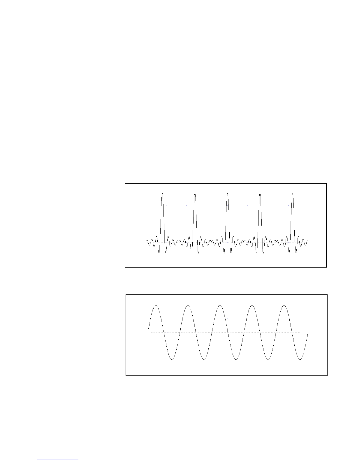
Getting Started
Functional Description
1
Sequenced
Waveforms
The sequence generator is a powerful tool that lets you link and
loop segments in any way you desire. As a simple example of a
sequenced waveform, look at Figures 1-5a through 1-5c. The
waveforms shown in these figures were placed in memory
segments 1, 2 and 3, respectively. The sequence generator takes
these three waveforms links and loops them in a predefined order
to generate the waveform shown in Figure 1-5d.
The sequence circuit is useful for generating long waveforms with
repeated sections. The repeated waveform has to be programmed
once and the repeater loops on this segment as many times as
selected. When in sequenced mode, there is no loss of time
between linked or looped segments.
Figure 1-5a, Segment 1 – Sin (x)/x Waveform
Figure 1-5b. Segment 2 – Sine Waveform
1-13
Page 31
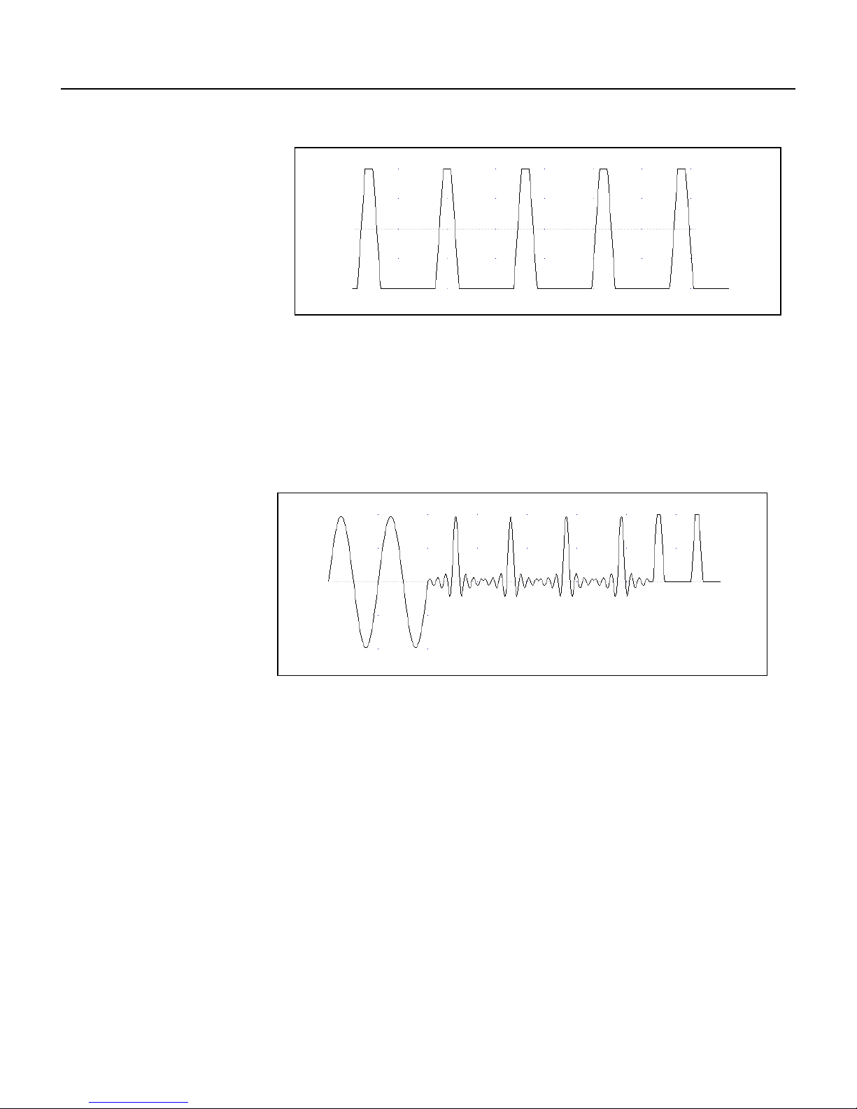
TE5251
User Manual
Figure 1-5c Segment 3 – Pulse Waveform
The following sequence was made of segment 2 repeated twice,
segment 1 repeated four times, and segment 3 repeated two times.
Modulated
Waveforms
Using the latest DDS (direct digital synthesis) technology, the 5251
is extremely agile. Operations like sweep, FSK and FM are directly
derived from the DDS circuit by controlling its input bits. The
modulated waveform schemes are described below.
Sweep
The 5251 can sweep from minimum to maximum sample clock
frequency boundaries. You may select to sweep up or down using
linear or logarithmic increments. Sweep time is programmable from
10 μHz to 100 MHz and sweep times can be set from 1.4 μs to 40
seconds. You may use the sweep in continuous, triggered, or gated
modes.
1-14
Figure 1- 5d. Sequenced Waveforms
Page 32

Getting Started
Functional Description
1
FM
AM
Frequency Hop
The FM function modulates the 5251 carrier output in the frequency
domain. You can modulate the output using the built-in waveforms
standard waveforms, or download complex waveforms to the
modulation memory. FM can be used in continuous, triggered and
gated modes. The 5251 can generate two types of frequency
modulation: 1) Standard and 2) Arbitrary. In standard mode, the
modulating waveform is selected from a built-in library of 4
standard waveforms: sine, triangle, square and ramp. In arbitrary
mode, complex modulating signals are loaded to the modulation
waveform memory. There are 10,000 points allocated specifically
for the arbitrary memory that is used for arbitrary frequency
modulation and hence 10k unique frequency values may be used
for this function.
The AM function modulates the 5251 carrier output in the amplitude
domain. There are four standard modulating waveforms that can be
used for the modulation scheme: sine triangle, square and ramp.
AM can be used in continuous, triggered and gated modes.
The frequency hop function causes the output frequency to hop
through a frequency list. The interval that the 5251 dwells on a
specific frequency is programmable for each hop. The dwell time
could also be set uniformly over the entire frequency list.
FSK
PSK
The frequency hop table can contain up to 1000 different frequency
values of which could range from 10 Hz to 100 MHz.
FSK (frequency shift keying) function shifts the carrier frequency
between two frequency settings. The trigger input is used for
programming the frequency value. Trigger false state generates
base frequency and trigger true state generates shifted frequency.
For positive true trigger state select the positive trigger slope and
for negative true trigger state select the negative trigger slope.
PSK (Phase shift keying) function shifts the phase of the carrier
frequency between two phase settings 0° and 180°. The trigger
input is used for programming the phase value. Trigger false state
generates 0° and trigger true state generates 180°. For positive
true trigger state select the positive trigger slope and for negative
true trigger state select the negative trigger slope.
1-15
Page 33

TE5251
User Manual
ASK
3D
Pulse Waveforms
ASK (amplitude shift keying) function shifts the amplitude of the
carrier frequency between two amplitude settings. The trigger input
is used for programming the amplitude value. Trigger false state
generates base amplitude and trigger true state generates shifted
amplitude. For positive true trigger state select the positive trigger
slope and for negative true trigger state select the negative trigger
slope.
The 3D function is operated from an external utility only, such as
ArbConnection. The carrier waveform can be programmed to
sweep in three dimensions: frequency, amplitude and phase.
Using the arbitrary memory, one may use the 5251 as a standalone pulse generator. All pulse parameters are adjustable
including period, pulse width, delay, rise and fall times as well as
double pulse parameters, just as you would program parameters
on a standard pulse generator. Pulse structure is limited only by the
resolution of the sample clock and the number of waveform points
that are required to create the pulse shape.
Half Cycle
Waveforms
Counter/Timer
Just as it is on a standard pulse generator, the pulses that are
generated from this function are limited to one or two pulses in a
pulse train and cannot change amplitude from train to train. For
applications that require complex pulse trains where multiple pulse
sequences that have variable amplitude profiles for each pulse, one
may use the Pulse Composer program that is available in
ArbConnection.
There are three half cycle waveforms that the 5251 generates:
sine, triangle and square. Frequency range is 10 mHz to 1 MHz
and the delay between the half cycles is programmable from 200
ns to 20 seconds with increments of 20 ns. One may also program
the start phase of the waveforms from 0.1° to 359.9°.
The 5251 can be made to operate as a stand alone counter/timer. It
can measure the following functions: frequency, period, period
averaged, pulse width and it also can accumulate and totalize
incoming pulses. The counter/timer can measure frequencies to
over 100 MHz within gate times of 100 μs to 1 s. Frequency and
period averaged are measured and display 7 digits in one second
of gate measurement time and with accuracy of 1 ppm.
1-16
Page 34

Getting Started
Output State
1
Output State
Filters
Programming The
5251
The main outputs can be turned on or off. The internal circuit is
disconnected from the output connector by a mechanical switch
(relay). This feature is useful for connecting the main outputs to an
analog bus. For safety reasons, when power is first applied to the
chassis, the main output is always off.
Two filters are built into the 5251. These filters are available for use
in various applications such as the creation of high frequency sine
waves and removing the staircase effect from waveforms that are
generated with high frequency clock rates. The filters are also used
for reconstructing the standard sine waveform.
The 5251 does not have front panel control capability. Also,
waveform data and sequence tables must be loaded to the 5251
from a host computer before it can be output arbitrary or
sequenced waveforms. There are a number of ways to “talk” to the
instrument. They all require that an appropriate software driver be
installed in the host computer. The rest is a matter of practice and
knowledge of the language in use. These topics are discussed in
later chapters.
Low level programming of the 5251 is accomplished using SCPI
(Standard Commands for Programmable Instruments) language.
Programming aspects are covered in Chapter 4.
Supplied with the 5251 is a PC software package called
ArbConnection. This software provides a user interface that allows
interacting with and controlling the 5251 directly. Details on how to
use ArbConnection are given in Chapter 3.
1-17
Page 35

TE5251
User Manual
This page was intentionally left blank
1-18
Page 36

Chapter 2
Configuring the Instrument
Title Page
Installation Overview .......................................................................................................... 2-3
Unpacking and Initial Inspection ..................................................................................... 2-3
Safety Precautions ......................................................................................................... 2-3
Operating ........................................................................................................................... 2-4
Environment ................................................................ ....................................................... 2-4
Power Requirements.......................................................................................................... 2-4
Grounding Requirements ................................................................................................... 2-4
Calibration .......................................................................................................................... 2-5
Abnormal Conditions .......................................................................................................... 2-5
Long Term Storage or Repackaging For Shipment ......................................................... 2-5
Preparation For Use ....................................................................................................... 2-6
Removing the Instrument from the Bag .............................................................................. 2-6
Installation .......................................................................................................................... 2-6
Installing Instrument Drivers ............................................................................................... 2-7
Installing Software Utilities ................................................................................................. 2-12
Installing IVI Drivers and ArbConnection ............................................................................ 2-13
Page 37

TE5251
User Manual
2-2
Page 38

2 E
Configuring the Instrument
Installation
Overview
This chapter contains information and instructions necessary to
prepare the Model 5251 for operation. Details are provided for initial
inspection, grounding requirements, repackaging instructions for
storage or shipment and installation information.
Unpacking and
Initial Inspection
Unpacking and handling of the generator requires normal
precautions and procedures applicable to handling of sensitive
electronic equipment. The contents of all shipping containers should
be checked for included accessories and certified against the
packing slip to determine that the shipment is complete.
Safety Precautions
The following safety precautions should be observed before using
this product and associated PXI chassis. Although some
instruments and accessories would normally be used with nonhazardous voltages, there are situations where hazardous
conditions may be present.
This product is intended for use by qualified persons who recognize
shock hazards and are familiar with the safety precautions required
to avoid possible injury. The following sections contain information
and cautions that must be observed to keep the 5251 operating in a
correct and safe condition.
CAUTION
For maximum safety, do not touch the product, test
cables, or any other instrument parts while power is
applied to the circuit under test. ALWAYS remove power
from the entire test system before connecting cables or
jumpers, installing or removing cards from the chassis.
Do not touch any object that could provide a current
path to the common side of the circuit under test or
power line (earth) ground. Always keep your hands dry
while handling the instrument.
Installation Overview
2-3
Page 39

TE5251
Operating
Environment
The 5251 is intended for operation within a PXI chassis chassis as
a plug-in module. Ensure the PXI chassis being used to host the
5251 fully conforms to the latest PXI specifications, including 3.3V
supply rail.
The 5251 is intended for indoor use and should be operated in a
clean, dry environment with an ambient temperature within the
range of 0 °C to 40 °C.
WARNING
The 5251 must not be operated in explosive, dusty, or
wet atmospheres. Avoid installation of the module
close to strong magnetic fields.
The design of the 5251 has been verified to conform to EN 610101 safety standard per the following limits:
Installation (Overvoltage) Category I (Measuring terminals)
Pollution Degree 2
Installation (Overvoltage) Category I refers to signal level, which is
applicable for equipment measuring terminals that are connected
to source circuits in which measures are taken to limit transient
voltages to an appropriately low level.
Pollution Degree 2 refers to an operating environment where
normally only dry non-conductive pollution occurs. Occasionally a
temporary conductivity caused by condensation must be expected
Power
Requirements
The 5251 operates from a PXI chassis. DC Voltages are
supplied to the instrument from the PXI connector. The
instrument requires a variety of DC voltages as outlined in the
Specifications section (Appendix A). Ensure the PXI bus is
capable of delivering required voltages and has sufficient current
to drive the generator.
CAUTION
Disconnect power to the PXI Chassis before installing
or removing the 5251.
Grounding
Requirements
To conform to the applicable safety and EMC requirements,
ensure that the 5251 instrument panel and the PXI chassis are
“earth” grounded.
User Manual
2-4
Page 40

2 E
Configuring the Instrument
CAUTION
The outer shells of the front panel terminals (OUTPUT,
SYNC OUT, TRIG IN, SCLK IN, 10M REF IN) are
connected to the instrument’s chassis and therefore to
the safety ground.
CAUTION
Do not attempt to float the OUTPUT from ground as it
may damage the 5251 and other equipment connected
to the 5251 I/O connectors.
Calibration
The recommended calibration interval is two years. Calibration
should be performed by qualified personnel only.
Abnormal
Conditions
Operate the 5251 only as intended by the manufacturer. If you
suspect the 5251 has been impaired, remove it from the PXI
chassis and secure against any unintended operation. The 5251
protection is likely to be impaired if, for example, the instrument
fails to perform the intended measurements or shows visible
damage.
WARNING
Any use of the 5251 in a manner not specified by the
manufacturer may impair the protection provided by
the instrument
Long Term
Storage or
Repackaging For
Shipment
If the instrument is to be stored for a long period of time or shipped
immediately, proceed as directed below. If you have any questions,
contact your local Tabor Electronics representative or the Tabor
Electronics Customer Service Department.
1. Repack the instrument using the wrappings, packing material
and accessories originally shipped with the unit. If the original
container is not available, purchase replacement materials.
2. Be sure the carton is well sealed with strong tape or metal
straps.
3. Mark the carton with the model and serial number. If it is to be
shipped, show sending and return address on two sides of the
box.
Calibration
2-5
Page 41

TE5251
NOTE
If the instrument is to be shipped to Tabor Electronics
for calibration or repair, attach a tag to the instrument
identifying the owner. Note the problem, symptoms, and
service or repair desired. Record the model and serial
number of the instrument. Show the returned
authorization order number (RMA) as well as the date
and method of shipment. ALWAYS OBTAIN A RETURN
AUTHORIZATION NUMBER FROM THE FACTORY
BEFORE SHIPPING THE INSTRUMENT TO Tabor
Electronics.
Preparation For
Use
Preparation for use include removing the instrument from the bag,
installing the 5251 inside the PXI chassis, copying instrument drivers
to the computer and installing the graphical interface (ArbConnection).
Installation
Plug the 5251 into your PXI’s chassis bus. Push the card firmly until
the PXI connector until the metal panel makes contact with the
metal edge of the PXI chassis. Using a suitable screwdriver, tighten
the retaining screw.
CAUTION
Disconnect power to the PXI Chassis before installing or
removing the 5251. An attempt to insert or remove the
instrument while the power is connected to the chassis
will result in severe damage to the instrument and will
automatically revoke your warranty.
CAUTION
Once the 5251 is installed in the chassis cover all
remaining open slots to ensure proper airflow. Using
the 5251 without proper airflow will result in damage to
the instrument.
Removing the
Instrument from
the Bag
The 5251 is supplied in an antistatic bag. Check the seal on the bag
to make sure the bag was not opened in a static-unsafe
environment. Place the enveloped card on static free surface and
hook yourself up with a grounding strap. Only then break the seal
and remove the card from the envelope. Hold the card at the metal
panel end. Refrain from touching the instrument with your finger at
all times.
User Manual
2-6
Page 42

2 E
Configuring the Instrument
Installing
Instrument Drivers
The 5251 is a Plug & Play instrument, meaning that after you install
it in your PXI chassis, Windows will automatically detect its
presence and will ask you to supply the appropriate drivers to
operate this instrument. After you copy the drivers, Windows will
add the drivers to the device manager and will assigns resources
for the instrument.
The 5251 is supplied with a CD that contains the *inf file for
installing the necessary drivers for operating the instrument on your
computer. Follow the instructions below to install the driver to your
computer.
Minimum System
Requirements
Minimum host system requirements for the instrument are as
follows:
1. Windows XP
2. 128 MB of RAM, 250MB or more recommended
3. 20 MB hard drive space
Windows Software
Installation
Note
The install program will automatically detect older
software version and you will be provided with a choice
of either removing it and installing newer versions, or
keeping your old installation intact. The install program
will not remove instrument drivers. In case you want to
remove the instrument driver from your computer, go to
the Windows Device Manager and remove the Arbitrary
Waveform Generator Model 5251 under the Tabor
Electronics heading.
In general, installation is very similar for different Windows variants
however, you should follow the exact procedure as applicable for
you’re your computer. The following paragraphs will guide you
through device driver installation for Windows XP.
Windows XP Device
Driver Installation
A device driver is necessary for the 5251 software to communicate
with PXI boards. The 5251’s installation CD includes instrument
drivers for supporting the required Windows platform. In Windows
XP, the installation package cannot automatically assign device
drivers for PXI devices and therefore leaving for the Plug & Play
Manager the responsibility for detecting devices and prompting the
user for the correct driver. To assign a driver to a device, Windows
refers to an *.INF file. The *.INF file provides instructions for
Windows as to which driver files to install and which registry entries
to insert. To install a driver for your 5251, complete the following
steps:
1. Power down your computer and PXI chassis.
Installing Instrument Drivers
2-7
Page 43

TE5251
2. Insert the 5251 board into a free PXI slot.
3. Power on your PXI chassis
4. Power on the computer. Windows should first detect the new
hardware device with a “Found New Hardware Wizard” message
box.
5. Windows then displays the “Found New Hardware Wizard” as
shown in Figure 2-1, which will search for new drivers
6. Follow the procedure as shown below.
Press Next and select one of the options in the dialog box below.
We recommend that you check the “Search for a suitable driver for
my device” option as shown in Figure 2-2.
User Manual
Figure 2-1 – The Welcome to the Found New Hardware Wizard
2-8
Page 44

2 E
Configuring the Instrument
Press Next and you’ll now be prompted to select the location of
your driver files on your computer as shown in Figure 2-3. Check
the “Specify a Location” option only.
Figure 2-2 – Install Hardware Device Drivers
Figure 2-3 – Locate Driver Files
2-9
Page 45

TE5251
The 5251 is supplied with an installation At this time, CD. Insert this
CD into your CD-ROM drive. If you already have the instrument
drivers installed somewhere on your computer, you can specify
your custom location. Either type in the complete path or click on
the Browse button to identify your driver location.
NOTE
After you insert the installation CD, Windows XP will
automatically load the autorun program and the CD
interface will show on your screen. The CD menu is not
required for the driver installation so you can either
leave the menu on screen and ignore it for now or click
on Exit to remove the application from your desktop. The
installation CD must be left in the CD-Rom drive for the
continuation of the installation process.
Press Browse… and specify the subfolder W2kdrv located in the
Drivers folder on your installation CD, as shown in Figure 2-4. Press
OK to acknowledge the selected path.
Windows displays the Driver Files Search Results as shown in
Figure 2-5. Click Next and then Finish completing the installation
process.
User Manual
Figure 2-4 – Copying Device Drivers
2-10
Page 46

2 E
Configuring the Instrument
The next step is necessary to verify that the device driver was
installed properly and is displayed correctly in the System Device
Manger. Do the following:
1. Click on the Start button, then Settings and then Control Panel.
2. In the Control Panel dialog box, find the icon labeled System.
3. Double click on the System icon and then on the Hardware
4. On the Hardware tab click on the Device Manager button.
5. Click on Tabor Electronics. If you installed the driver properly,
your device manager should show the Arbitrary Waveform
Generator Model 5251 as shown in figure 2-7.
Figure 2-5 – Driver Files Search Results
Figure 2-6 – Completing the Found New Hardware Wizard
2-11
Page 47

TE5251
Click on “X” to remove the System Properties dialog box from the
screen.
Installing Software
Utilities
The 5251 is supplied with a CD that contains the following
programs: IVI Driver, ArbConnection, device driver and some other
utilities to aid you with the operation of the instrument, including a
manual in pdf format. It is recommended that you stow away the CD
in a safe place after you load the drivers and the necessary utilities
to control the 5251.
The IVI driver is a useful utility that provides standard
communication and commands structure to control the 5251 from
remote. Programming examples are also available to expedite your
software development. The IVI driver comes free with the 5251
however, you’ll need the IVI engine and visa32.dll run time utilities
to be able to use the IVI driver. The additional utilities can be
downloaded for free from NI’s (National instrument) web site –
www.ni.com.
ArbConnection is a user friendly program that lets you control
instruments functions and features from a remote computer. It also
lets you generate and edit arbitrary waveforms on the screen, build
sequence tables, modulating signals and much more and then
download the signals to your 5251 without the hustle of writing
complex programs and utilities. This is also a great tool for you to
experiment simple, or complex command string to gain experience
User Manual
Figure 2-7 – Device Manager
2-12
Page 48

2 E
Configuring the Instrument
before you write your own code. ArbConnection has a command
editor feature that allows direct low-level programming of the 5251
using SCPI commands, just as you will be using them in your
program. Installation of ArbConnection is simple and intuitive and
only requires that visa32.dll runtime file be added to your Windows
system folder. Download the file from NI’s (National instrument)
web site – www.ni.com. Installation and operating instruction for
ArbConnection are given in Chapter 4.
The Device driver is mandatory to operate the 5251. If you do not
intend to use any of the IVI or ArbConnection software utilities, you
must copy the dll to your development folder. If you install the IVI
driver and ArbConnection, the dll is automatically installed in your
Windows->System32 sub-folder.
Installing IVI
Drivers and
ArbConnection
ArbConnection or the IVI drier are two software utilities that one of
them must be installed on your computer for you to be able to
operate and control the 5251. ArbConnection has three basic
function: 1) Control instrument setups, 2) Create, edit and download
complex arbitrary waveforms to your instrument and 3) Create, edit
and download complex (frequency) modulating waveforms.
Advanced users may want to write their own applications to control
the 5251 functions and features. For this purpose, C++ libraries and
DLL’s are available on the CD and can be copied to your
application folder. This is done automatically when installing the IVI
driver. However, if you are first time user and can’t wait to get your
hands on some controls and waveforms, it is recommended that
you install ArbConnection now. ArbConnection and waveform
generation aspects are covered in other sections of this manual.
To proceed with the installation process, insert the supplied CD into
your CD-ROM drive and wait for a GUI (Graphical User Interface) to
pop up on your screen. If you wait for a long time and the GUI fails
to load it is possible that your computer is not set up to load CD
programs automatically. In this case, Invoke Run and type:
N:\Autorun.exe (where N is your CD drive letter)
To install the software click on “Install Software Utilities” and follow
the install program as shown in Figure 2-8. The preparing phase
will check few things such as if your computer has any previous
installations installed on.
If you are an advanced user and in preparation to write your own code
and application, you’ll have to copy support libraries and some DLL’s
from the installation CD. In this case, select the “Copy Developer
Libraries” option and specify the folder location for your application.
The function of the libraries and other programming aspects are cover
in the programming section of this manual.
Installing IVI Drivers and ArbConnection
2-13
Page 49

TE5251
After finishing the “Preparing to Install” phase, the install wizard
shown in Figure 2-9 will take you to the first installation step
assuming that no problems were detected.
User Manual
Figure 2-8 – Install preparation
Figure 2-9 – First Installation Step
2-14
Page 50

2 E
Configuring the Instrument
Press Next and type the customer details at the “Customer
Information” Window, as shown in Figure 2-10.
After typing the customer details press Next and select the Setup
Type. You can select from three options: 1) Select 5251 if you
purchased and are installing the 5251, or 2) Select Custom if you
are an advanced user and want to refine your installation process.
We recommend that you install using option above and complete
the installation process by clicking on the Next button and then
Finish. If you select the Custom option, then you’ll have to type in
some other parameters such as new path for your destination folder
and choosing which feature to install, as shown in Figures 2-11.
Figure 2-10 – Customer Information Step
2-15
Page 51

TE5251
If you select the Custom option, proceed to change your Destination
Folder, as shown in Figure 2-12, by pressing the Browse button,
select the appropriate path, press OK and then press Next.
User Manual
Figure 2-11 – Selecting Setup Type
Figure 2-12 – Selecting Destination
2-16
Page 52

2 E
Configuring the Instrument
The final step to complete the installation process, you’ll be
prompted to restart your computer. You can select to either restart
your computer immediately or do it later, but remember that the
software will not function properly if you do not restart your
computer.
Figure 2-13 – Setup Complete
2-17
Page 53

Chapter 3
ArbConnection
Title Page
What’s in This Chapter? ....................................................................................................... 3-3
Introduction to ArbConnection ............................................................................................. 3-3
Installing ArbConnection ...................................................................................................... 3-3
Quitting ArbConnection ................................................................................................. 3-4
For the New and Advanced Users ................................................................................ 3-4
Conventions Used in This Manual ................................................................................. 3-4
The Opening Screen ............................................................................................................ 3-5
ArbConnection Features ...................................................................................................... 3-6
The Control Panels .............................................................................................................. 3-7
The Operation Panels .................................................................................................... 3-8
Main ........................................................................................................................... 3-9
Standard ................................................................................................................... 3-11
Arbitrary/Sequence .................................................................................................. 3-12
Using the Memory Partition Table ........................................................................... 3-14
Using the Waveform Studio ..................................................................................... 3-15
Trigger ...................................................................................................................... 3-19
The Modulation Panels ................................................................................................ 3-21
FM ............................................................................................................................ 3-21
AM ............................................................................................................................ 3-22
Sweep ...................................................................................................................... 3-23
ASK/FSK/PSK .......................................................................................................... 3-24
Frequency Hop ........................................................................................................ 3-26
The Auxiliary Panels .................................................................................................... 3-28
Counter/Timer .......................................................................................................... 3-28
Pulse Generator ....................................................................................................... 3-30
Half Cycle ................................................................................................................. 3-31
The System Panels ..................................................................................................... 3-32
General/Filters ......................................................................................................... 3-32
Calibration ................................................................................................................ 3-33
3-1
Page 54

TE5251
User Manual
The Composers Panels ............................................................................................... 3-34
The Wave Composer ............................................................................................... 3-35
The Toolbar ................................................................................................................. 3-41
The Waveform Screen ................................................................................................ 3-42
Generating Waveforms Using the Equation Editor ............................................................ 3-43
Writing Equations ........................................................................................................ 3-45
Equation Convention ................................................................................................... 3-46
Typing Equations ......................................................................................................... 3-47
Equation Samples ....................................................................................................... 3-48
Combining Waveforms ................................................................................................ 3-52
The Pulse Composer ............................................................................................... 3-53
The FM Composer ................................................................................................... 3-71
The 3D Composer ................................................................................................... 3-75
The Command Editor ......................................................................................................... 3-80
Logging SCPI Commands ................................................................................................. 3-81
3-2
Page 55

ArbConnection
What’s in This Chapter?
3
What’s in This
Chapter?
Introduction to
ArbConnection
This Chapter contains information how to install, invoke and use
ArbConnection. Introduction to ArbConnection and examples how
to program instrument controls and parameters and how to
generate waveforms and download them to the 5251 are also given
in the following sections.
In general, ArbConnection is a utility program that serves as an aid
for programming the Model 5251. ArbConnection has many
functions and features of which all of them share a common
purpose – controlling 5251 functions from remote. As minimum, to
use ArbConnection, you’ll need the following tools:
1. Computer, Pentium III or better
2. Windows 2000/XP, or higher
3. High resolution screen, at least, 1024 x 768 pixels
4. Pointing device, mouse or ball
5. Visa 2.6, or higher installation
6. Last, but not least, some basic knowledge how to operate
computers and Windows-based programs.
Installing
ArbConnection
ArbConnection operation is divided into three main functions: 1)
Front panel control, 2) Waveform generation and editing and 3) Low
level SCPI editing. These operating options are described in this
chapter however, you must install ArbConnection before you can
use it. The next paragraphs describe installation and first steps
before going into in-depth operation.
The installation program installs ArbConnection on a logical drive of
your choice. The default is drive C. It automatically creates a new
directory and copies the files that are required to run the program.
Before you install ArbConnection, make sure that there is at least
10 megabytes of available memory on your hard disk drive.
To install ArbConnection, insert the distribution CD in the CD drive
and follow the on-screen instructions to install ArbConnection. If
your computer fails to detect the CD, access the CD from My
Computer and invoke the Setup command.
The install program does the complete job far you and creates a
workgroup and icons to start ArbConnection.
3-3
Page 56

TE5251
User Manual
Quitting
ArbConnection
For the New and
Advanced Users
Before you start roaming through menus and editing commands, we
strongly recommend that you make yourself familiar with
ArbConnection basics and concept. For now quit the program and
spend some more time with this section of the manual. Point the
mouse cursor to the File menu and press the left mouse button.
Move the mouse cursor to the Exit command and press the left
mouse button.
For the New User
Learning to use ArbConnection is easy, intuitive and quick, even if
you have never used such programs before. After you have
installed ArbConnection on your computer read the following
paragraphs to learn how to find your way around ArbConnection’s
menus.
Once you are familiar with the basics, you’ll continue to learn about
features, programming, and editing commands. If you can’t find the
answer to a question in this guide, call your distributor or the
LeCroy customer support service near you and we’ll gladly assist
you with your problems.
For the Advanced User
If you are already familiar with computer conventions and have
basic knowledge of Windows programming, you may want to skip
some of the following paragraphs.
Conventions Used
in This Manual
This manual uses certain typographical conventions to make it
easier for you to follow instructions. These conventions are described in the following:
[Enter, or ↵] Press the Enter or Return key.
[Esc] Press the Escape key.
[Alt-F] Press the Alt key and the key that follows, simultaneously. In
this example the key that follows is F.
[Ctrl-S] Press the Control key and the letter that follows, simulta-
neously. In this example, the letter is S. The control key also
appears in the menus as a target sign.
[↑] [↓] [→] [←] Press the Arrow key with the symbol pointing in the
direction specified (i.e., up, down, left, or right).
<+> Press the key for the character or word enclosed in angle
brackets. In this case, the Plus sign key.
3-4
Page 57
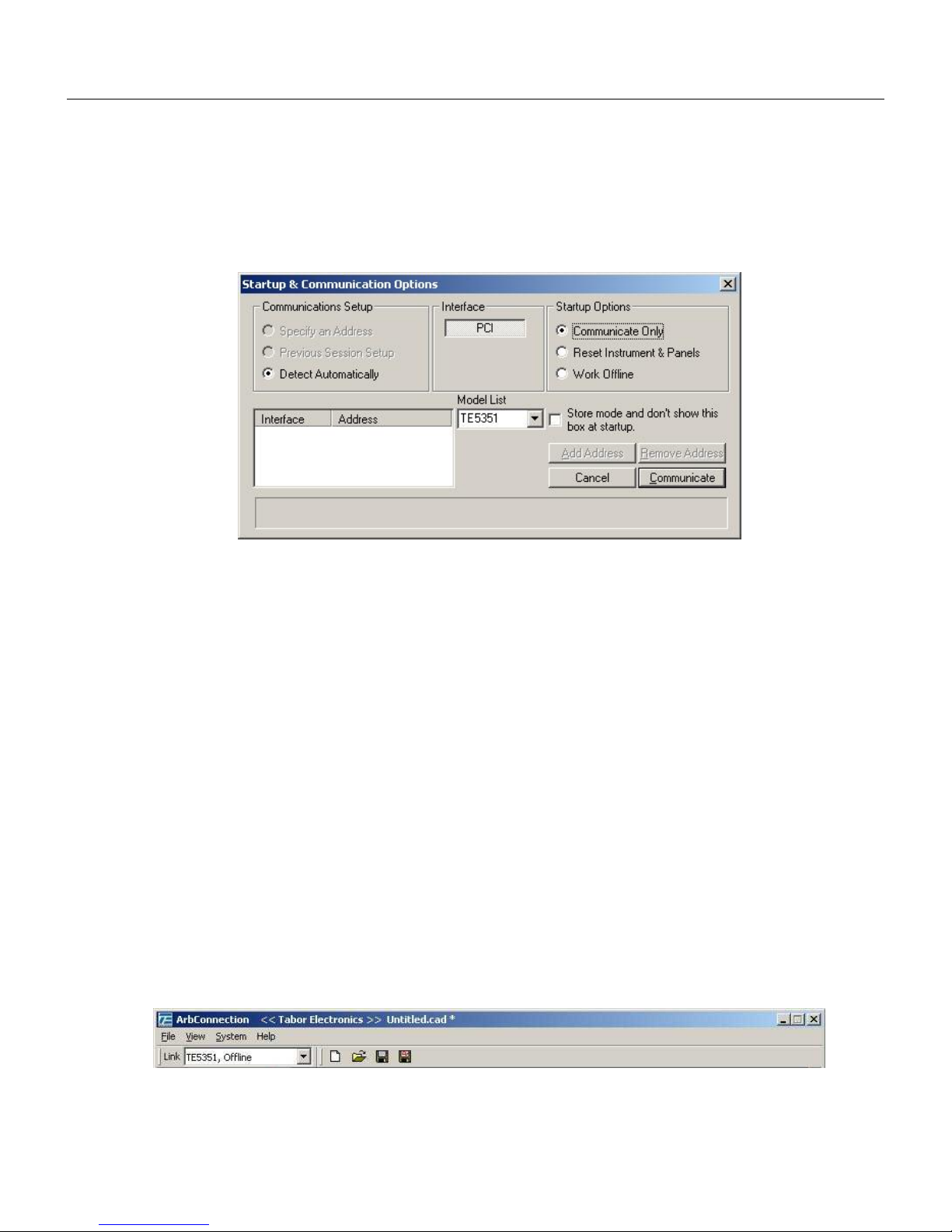
ArbConnection
The Opening Screen
3
The Opening
Screen
Invoke ArbConnection by double clicking on the icon. If you cannot
find the icon on your desktop, click on Start, Programs and
ArbConnection. The opening screen will show. If you installed the
program correctly, your screen should look as shown in Figure 3-1.
Figure
3-1, Startup & Communication Options
The Startup & Communication Options dialog box is displayed. You
can check the “Store mode and don’t show…” so next time you
invoke ArbConnection, this dialog box will not be displayed. The
purpose of this dialog box is to update the program in the way you
intend to use it. For example, if you are using two cards in your
computer but intend to use a specific device, you can click on the
Specify an Address option and type in the required address so the
next time you use ArbConnection, the program will automatically
resume communication with the same card address as was
originally detected.
If you chose to hide this dialog box, you can still access and change
the options from the System command, at the top of the screen.
Make your selection and click OK. The Startup & Communication
Updater dialog box will be removed from the screen. And the Main
panel will now be accessible. But before we go into panel operation,
let’s look at the toolbars at the left top of the screen as shown in
Figures 3-2 and 3-3.
Figure 3-2, ArbConnection's Toolbars
3-5
Page 58
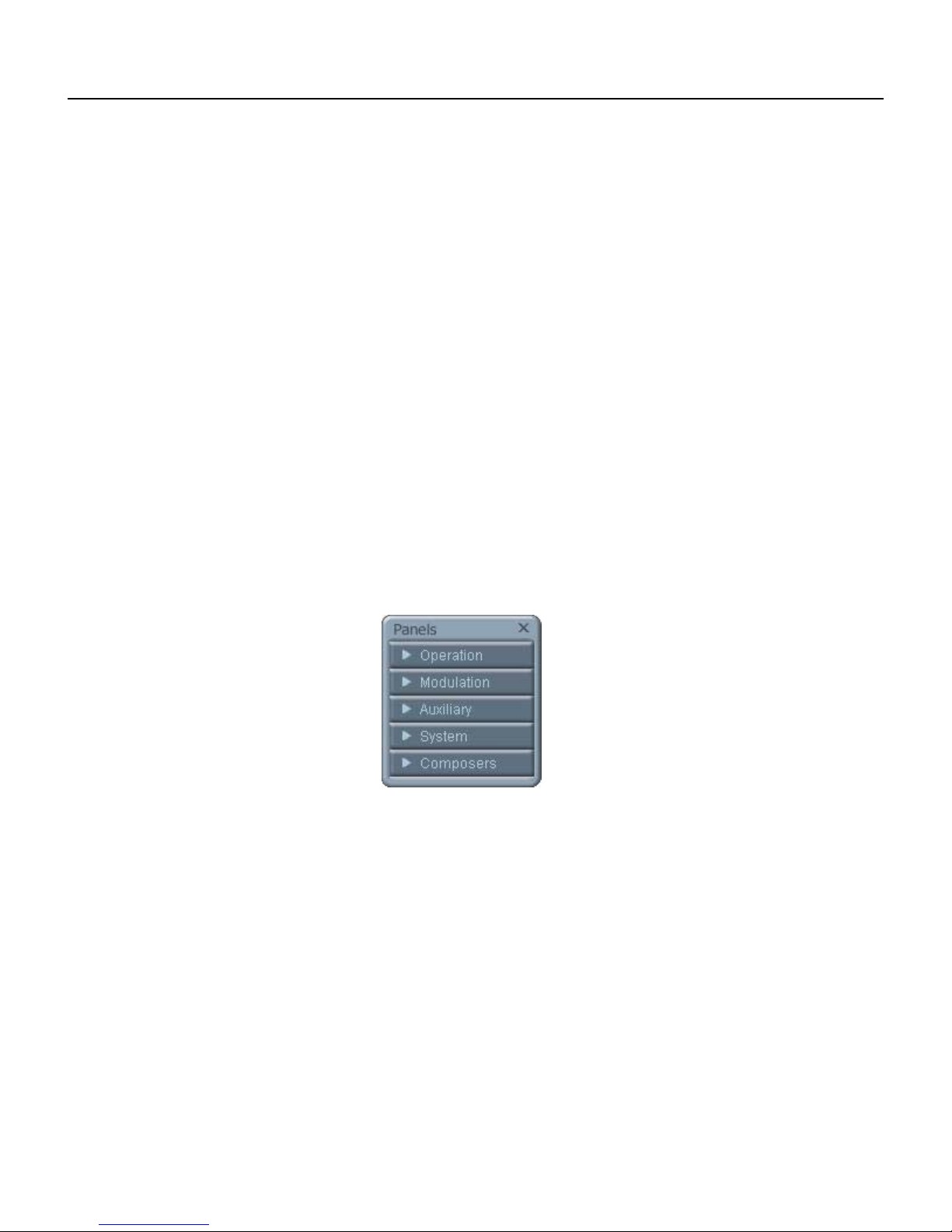
TE5251
User Manual
The standard Windows Menu Bar is the top bar. It provides access
to main system controls like saving files, and viewing or removal of
screen images.
The second bar is called Link bar. It provides direct access to
different instruments that are active on the active interface bus.
ArbConnection can control a number of 5251 units simultaneously.
If the instruments were connected to the interface while invoking
ArbConnection, they will automatically be detected by the program
and will be placed in the Link pull-down window. The active
instrument is displayed with its associated address. If you run
ArbConnection in offline mode, the Link bar will show 5251, Offline.
The Panels toolbar, as shown in Figure 3-3, provides direct access
to instrument control panels. The individual control panels are
explained later in this chapter. The Main, Standard, Arbitrary,
Trigger and the other buttons will bring up to the screen panels that
are associated with these names. The Composers button provides
access to the Waveform and Pulse composers. The first time you
launch ArbConnection, the opening screen will have the Main panel
open. Click on other buttons and interactively get the feel how
ArbConnection opens and closes control panels.
ArbConnection
Features
3-6
ArbConnection’s main purpose is controlling 5251 functions and
parameters. The 5251 can generate standard waveforms from a
built-in library, arbitrary waveforms from user-downloaded
coordinates, modulated waveforms, digital patterns and much more.
The only way to access all of these features is through software
utilities such as Plug & Play drivers, and soft front panels.
ArbConnection is built to provide complete control over the 5251.
ArbConnection has three main screens: control panels, waveform
composers and various utility control panels. The various screen
images along with instructions how to access and use them are
described below in detail.
Figure 3-3, the Panels Toolbar
Page 59

ArbConnection
The Control Panels
3
The Control
Panels
The control panels look and feel just as if you would operate an
instrument from its front panel. They even look like instrument front
panels, so operating function and changing parameters is easy and
intuitive. Let’s look at the first panel that shows at the opening
screen. This panel, as shown in Figure 3-5, is called the Main
Panel.
To begin with, let’s explore the panel controls to see how they feel,
react and what they do. All other panels share almost the same
feel, so the description of how to operate the Main Panel can serve
as general guide for controlling the rest of the panels.
Looking at the panel you can identify the following controls: Push
buttons, LED’s, radio buttons, Dial and Digital display. The function
of each control is described below.
Push Buttons – These are used for toggling a function on and off.
For example, the Output Enable button in the Output group toggles
the output on and off. The first mouse click will push the button
inwards and will turn on a red bar at the center of the button,
indicating that the function is on. The second mouse click will turn
the function off.
Radio Buttons – Are used for changing operating modes, or
selecting between mode options. One of the radio buttons is always
on with a red dot in its center, indicating its state condition.
LED’s – The LED’s indicate which of the parameters are displayed
on the Digital Display. Red LED indicates that the parameter name
next to this LED is selected. Only one LED can be ON at a time.
HINT
LED’s are turned on by clicking on the LED or the text
next to it. The selected parameter is flagged by a darker
LED shade.
Dial – Use the dial to modify displayed reading. To use the dial,
press and hold the mouse cursor on the dial and move the mouse
in a clockwise circle to increase the number, or counterclockwise
circle to decrease the displayed number. The dial modifies digits at
the cursor position and will allow modification within the legal range
of the displayed parameter. If you reach the end of the range, the
dial will have no further effect on the display. If you do not want to
use the dial, you can still change the display reading by using the
[↑], or [↓] keys, or simply type the required number using the
standard keyboard features.
3-7
Page 60

TE5251
User Manual
NOTE
After you change the displayed readout, the 5251 will be
updated with the new parameter only after you press the
Execute button.
Digital Display – The display is used for displaying and reading
various 5251 parameters, just as you would use it on your
instrument.
Note
Normal color of the digital reading is dark blue. If you
modify the reading, the color changes to a lighter shade
of blue, indicating that the 5251 has not been updated
yet with the new parameter. Pressing Execute will
update the instrument and will restore the color of the
digital readout to dark blue, indicating that the displayed
value is the same as the generator setting.
Also note that the digital readout has an autodetect
mechanism for the high and low limits. You cannot
exceed the limits if you are using the dial but only if you
use the keypad. In case you do, the program will not let
you download an illegal parameter and you’ll be
requested to correct your setting.
The Operation
Panels
The Operation tab provides access to a group of panels that control
the basic operation of the generator. From this group you can set
the output function, run mode, turn the outputs on and off and
adjust the parameters for the various functions. There are four
panels in this group: Main, Standard, Arbitrary/Sequence and
Trigger. The Main panel is always visible because this is the panel
that controls operating functions, run modes and sets the outputs
on and off. The other panels can be made visible by clicking on the
appropriate tab in the Operation group. The Operations Panels bar
is shown in Figure 3-4 and the operation panels are described
below.
3-8
Page 61

ArbConnection
The Control Panels
3
Figure 3-4, the Operations Panels
Main
The Main Panel, as shown in Figure 3-5, is the first panel you see
after invoking ArbConnection. Notice how buttons and LED’s are
grouped; this is done specifically so that common parameters are
placed in functional groups. The Main Panel groups allow (from left
to right) adjustment of amplitude and offset, selection of waveform
mode, selection of run mode and control over SYNC and Main
output parameters. Controls, where applicable, are provided for
each channel separately.
Figure 3-5, the Main Panel
3-9
Page 62

TE5251
User Manual
If you are connected properly to a PC and ArbConnection has
detected your instrument, then every time you press a button, you
are getting an immediate action on the 5251. It is different if you are
changing parameters on the display; Doing this, you’ll have to press
the Execute button for the command to update the instrument. The
functional groups in the Main Panel are explained below.
Parameters
The Parameters group has two parameters for each channel:
Amplitude and Offset. To access the required parameter, click on
the LED or the text next to it to display the required parameter. The
value that is associated with the lit LED is displayed on the digital
display. You can use the dial, keyboard, or the [↑] [↓} keys to adjust
the readout to the required setting. After you modify the reading,
press Execute to update the 5251 with the new reading.
Function
The Function group is used for selecting between function types.
The 5251 provides four types of waveforms: Standard, Arbitrary,
Sequenced and Modulated. By pressing one of these buttons
output waveform will change to the selected option. The default
function type is Standard. If you want to change standard waveform
parameters, you can select Standard from the Panels bar.
Run Mode
The Run Mode group is used for selecting the active run mode for
the instrument. You can select between continuous, triggered,
gated and burst modes. There is no additional panel associated
with the continuous mode, but if you press one of the other run
mode options, you’ll be able to adjust the trigger parameters from
the Trigger Panel.
Output Control
The Output Control group controls the state of the main outputs and
the sate of the SYNC output. Click on the State buttons to toggle
the outputs on and off.
From this group you also control the position of the SYNC pulse.
The load impedance buttons allow you to adjust the display
amplitude reading to your actual load impedance value. The default
value is 50 Ω and the output range is calculated in reference to this
value. If your actual load impedance is higher than 50 Ω and you
increase the load impedance value in this group, the output of the
5251 will display the correct value as is measured on your load
impedance.
3-10
Page 63
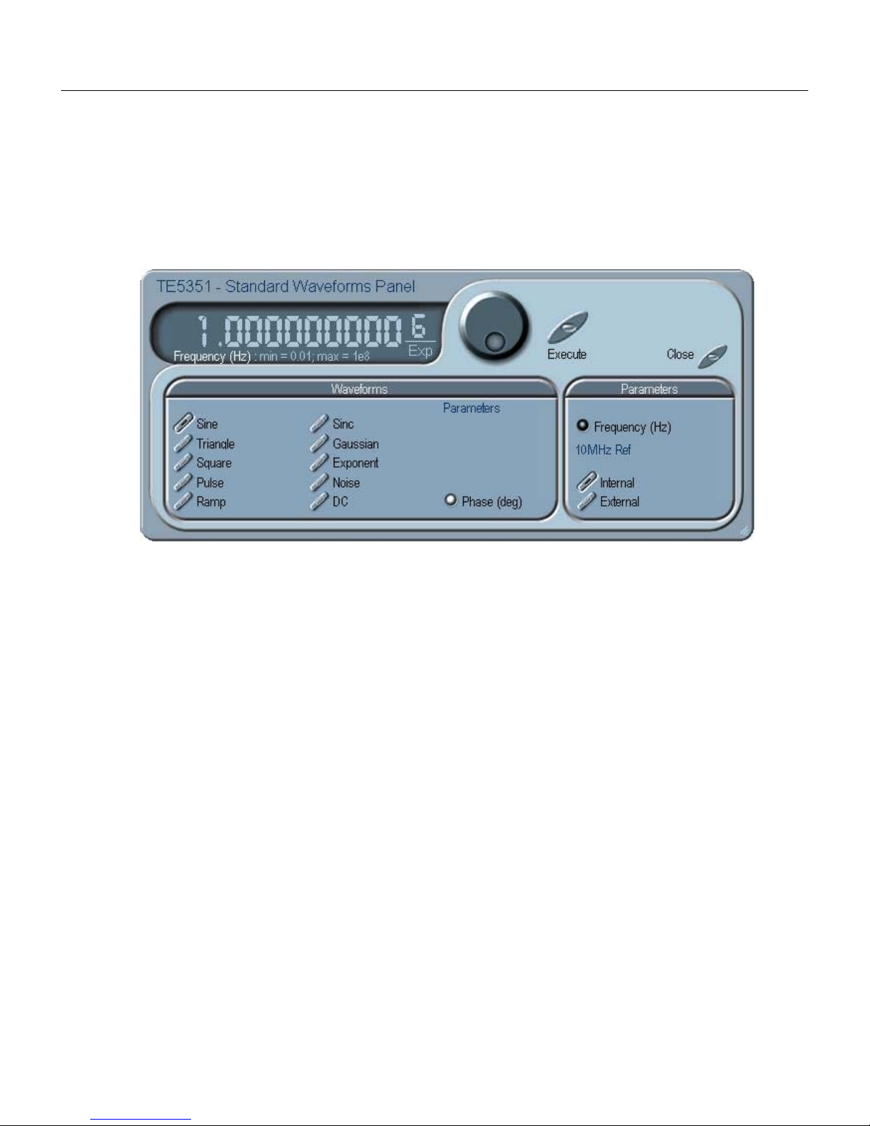
ArbConnection
The Control Panels
3
Standard
The Standard Panel, as shown in Figure 3-6, is accessible after you
click on the Standard button in the Panels bar. The Standard
Waveform Panel groups allow (from left to right) adjustment of
waveforms and their associated parameters. The functional groups
in the Standard panel are described below.
Figure 3-6, the Standard Waveforms Panel
Waveforms
The Waveforms group provides access to a library of built-in
standard waveforms. The library includes: Sine, Triangle, Square,
Pulse Ramp, Sinc, Exponential, Gaussian and DC waveforms.
Each waveform has one or more parameters that can be adjusted
for the required characteristics of the output. For example, phase
start can be adjusted for the sine and triangle waveforms and dutycycle can be adjusted for the square waveform. The pulse
waveform can be adjusted for rise and fall time as well as width and
delay. Parameters that are associated with each waveform are
automatically displayed when the waveform is selected.
Note that by clicking a button in this group, you are immediately
updating the 5251 output with this waveform shape.
Parameters
The parameters group contains buttons that control the source of
the 10 MHz reference and the setting of the output frequency for the
standard waveforms function.
The 10 MHz Ref controls toggle between an internal and external
references. The default setting is internal, which provides frequency
accuracy of 1 ppm. If such accuracy is not sufficient for your
application, click on the external option but make sure that a
reference source is applied to the rear panel connector; otherwise,
the accuracy of the output will deteriorate completely.
3-11
Page 64

TE5251
User Manual
The Frequency control lets you program the output frequency of the
selected waveform shape. The frequency parameter may be
modified when the LED illuminates. You can use the dial, keyboard,
or the [↑] [↓} keys to adjust the readout to the required setting. After
you modify the reading, press Execute to update the 5251 with the
new reading.
Arbitrary/Sequence
The Arbitrary & Sequence panel, as shown in Figure 3-7, is invoked
by pressing the Arb/Seq button on the Panels bar. Note that if you
invoke the Arbitrary & Sequence Panel from the Panels menu, the
5251 will not change its output type. On the other hand, if you select
the arbitrary, or the sequenced options from the Main Panel, the
5251 will immediately change its output to the selected waveform
type. The functional groups in the Arbitrary Waveforms Panel are
described below.
Parameters
The Parameters group contains three parameters: Amplitude,
Offset and Segment. Actually, the amplitude and offset values
exhibited in this group are exactly the same as in the Main Panel,
so every time you change amplitude and offset in the Parameters
group, the other panels are updated automatically. The segment
parameter provides access to the active segment for each channel.
By selecting a segment as active, the sync pulse is attached to this
specific segment number.
To access the required parameter, click on the parameter name.
The LED next to the required parameter turns on. The value that is
associated with the lit LED is displayed on the digital display. You
can use the dial, keyboard, or the [↑] [↓} keys to adjust the readout
to the required setting. After you modify the reading, press Execute
to update the 5251 with the new reading.
Figure 3-7, the Arbitrary & Sequence Panel
3-12
Page 65

SCLK
The SCLK (Sample Clock) group is comprised of parameters that
control the sample clock frequency. The sample clock setting
affects the 5251 in arbitrary mode only.
The sample clock rate is programmed in units of S/s (samples per
second) and will affect the instrument only when it is programmed
to output arbitrary or sequenced waveforms. The SCLK parameter
has no effect on the frequency of the standard waveforms.
The two switches in the SCLK group select between internal and
external sample clock inputs. The internal is the default setting.
When you select the external sample clock option, make sure an
appropriate signal is connected to the external sample clock
connector on the rear panel.
To access the required parameter, click on the button until the LED
next to the required parameter turns on. The value that is
associated with the lit LED is displayed on the digital display. You
can use the dial, keyboard, or the [↑] [↓} keys to adjust the readout
to the required setting. After you modify the reading, press Execute
to update the 5251 with the new reading.
10 MHz Ref
The 10 MHz Ref controls toggle between an internal and external
references. The default setting is internal, which provides frequency
accuracy of 1 ppm. If such accuracy is not sufficient for your
application, click on the external option but make sure that a
reference source is applied to the rear panel connector; otherwise,
the accuracy of the output will deteriorate completely.
ArbConnection
The Control Panels
3
Sequence
The Sequence Advance Mode group provides control over advance
modes for the sequence generator. Advance options are: Auto,
Stepped, Single and Mixed. Refer to the 5251 manual to find out
more when and how to use these advance modes. You should be
careful while selecting modes because it is possible to cause
settings conflict, for example, if you select the Single option before
you modified the run mode to Triggered.
Memory Management
The memory management group provides access to the memory
partition and waveform studio screens. The Waveform Partition
button opens a screen as shown in Figure 3-8 and the Waveform
Studio button opens a screen as shown in Figure 3-9. Information
how to use these screens is given in the following paragraphs.
3-13
Page 66

TE5251
User Manual
Using the Memory
Partition Table
If you want to learn more about waveform memory and segment
control, you should refer to section 2 of this manual. In general, the
5251 can generate arbitrary waveforms but, before it can generate
waveforms, they must be downloaded to the instrument from a host
computer. Waveforms are downloaded to the instrument as
coordinates and are stored in the 5251 in a place designated as
“waveform memory”. The waveform memory has a finite size of 2M.
Having such long memory does not necessarily mean that you have
to use the entire memory every time you download a waveform. On
the contrary, the 5251 allows segmentation of the memory so that
up to 10,000 smaller waveforms could be stored in this memory.
There are two ways to divide the waveform memory to segments:
1) Define a segment and load it with waveform data, define the next
and load with data, then the third etc. or 2) Use what ArbConnection
has to offer and that is to make up one long waveform that contains
many smaller segments, download it to the instrument in one shot
and then download a memory partition table that splits the entire
waveform memory into the required segment sizes. Want to use it?
Here is how it is done. Point and click on the Memory Partition. A
dialog box as shown in Figure 3-8 will pop up.
Figure 3-8, the Memory Partition Table
The two main fields in the segment table are Segment number and
segment size. The Seg No (segment number) is an index field that
can has values only, from 1 to 10,000. The Segment Size is always
associated with the segment number. You can program any
segment size from 16 to 2 M.
Use the Append key to add a segment at the end of the segment
list. If you highlighted a segment, the Append key turns
automatically to insert Use the Insert key to insert a segment at the
cursor location. The Delete key is used for deleting a segment at
the cursor position.
3-14
Page 67

The Clear All key will remove all segments from the table and will
let you start designing your segment table from fresh.
Click on the Close to discard of the contents of the dialog box
without saving your last actions and to remove the Segment Table
from the screen.
ArbConnection
The Control Panels
3
Using the Waveform
Studio
The Save key saves the current session so you can start the
Memory Partition table from the same point after you close this
session. The Download key updates the 5251 with the present
segment table settings.
TIP
The Memory Partition table does not download
waveforms. Use the memory partition table only if you
merged a few waveforms to one. The partition table then
divides the memory to the individual and original size of
each waveform. If you download waveforms using the
waveform studio, they already contain segment size and
there is no need for further use of the memory partition
table.
The Waveform Studio, as shown in Figure 3-9 has two parts: 1)
Segment Table and 2) Sequence Table. The purpose of the
waveform studio is to provide access to waveform files that are
already resident in the system. These files can be delegated to
various segments and later be used as individual waveforms or
combined into complex sequences.
The Segment Table
Using the Segment Table you may list and download waveform files
that were previously stored on the computer. The table shows the
segment number and its associated file name, length and its
download status. There are other means to download waveforms to
memory segments such as the Wave Composer and individual
function calls; The waveform studio makes it easier by combining
multiple and complex commands into one simple dialog box.
To access the Segment table, click anywhere on the Segment
Table area. If it was not yet, it will turn white as opposed to the
Sequence Table area that turns gray. The Segment Table area is
divided into three parts: the table area, the waveform shape area
and control buttons. When you point and click on one of the
waveforms, its shape is shown in the Waveform Shape window.
The Segment Table has four fields:
The Seg field contains numbers from 1 through 2048, designating
the programmed memory segment. Note that memory segments
are numbered from 1 to 2048.
3-15
Page 68
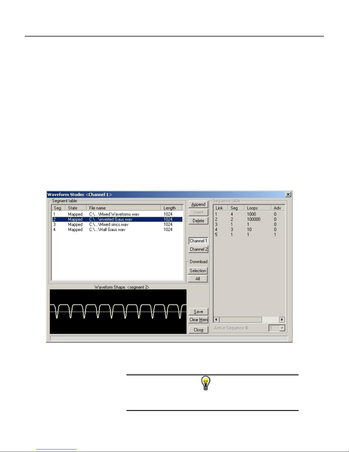
TE5251
User Manual
The State field shows the current status of the memory segment. It
can be Free, if no file has yet been assigned to this segment
number, or Mapped, if file name has been assigned to the segment
but the Download button has not been used yet to move the file to
the 5251 memory, or Loaded, if the process has been completed by
pressing either the Download button or the All (download all) button.
The File field is an edit field that lets you browse and select file
names to be applied to a specific memory segment. To change or
add file name, point and click on the File name field and either type
your path or browse to the file location and let Windows find the
right path.
The Length field displays the length of the selected memory
segment. Memory segments size may be programmed from 16 to 2
M. Note that the length field is not accessible and shown for
reference purpose only.
3-16
Figure 3-9, the Waveform Studio
TIP
Point and click on one of the segments to show its
shape in the Waveform Shape window.
Page 69

ArbConnection
The Control Panels
3
Description of the various buttons in the Segment Table is given
below.
Append – adds segment number at the end of the table
Insert – adds a segment above a highlighted segment line
Delete – removes a highlighted segment
Save – saves current table settings
(Download) Selection – downloads a highlighted segment only to
the 5251 memory
(Download) All – downloads the complete table to the 5251
memory
Clear Mem – wipes out the entire memory and clears the table for
fresh settings
Close – removes the Waveform Studio from the screen. If you have
not saved your work, the table setting will be lost.
The Sequence Table
As was explained in the above, the waveform memory can be
divided into smaller segments and up to 2048 segments can be
defined and used as individual arbitrary waveforms. Having a
limited size of waveform memory can, for some applications, pose a
limitation however, if sections of the waveform are repetitive, one
may use the sequence generator to take these segments and
replay them as part of the complete waveform without loosing
valuable memory space and without scarifying waveform
coherences, or integrity. The tool for using repetitive and multiple
segments in one long waveform is called Sequence Generator. The
5251 has two separate sequence generators, one for each channel
and ArbConnection has a special dialog box where sequences are
designed. This tool is called – Sequence Table.
Using the Sequence table you can use waveforms that you already
downloaded to the 5251 from the Segment table, link and loop in
random order to create one long and complex waveform that
combines the individual memory segments.
3-17
Page 70

TE5251
User Manual
Figure 3-10, the Sequence Table
The Sequence Table is demonstrated in Figure 3-10. To access the
Sequence table, click anywhere on the Sequence Table area. If it
was not yet, it will turn white as opposed to the Segment Table area
that turns gray.
There are four major elements that you should consider while
programming a sequence table. They are: Link, Seg, Loops and
Adv. These terms are explained below.
Link - This parameter defines an index array for the sequence
generator. When generating sequences, the instrument steps
though the links in descending order therefore, make sure that you
enter your waveform segments in exactly the order you would like
them at the output.
Seg - This parameter associates waveform segments with links.
You can use different segments for different links or you can use
the same segment for a number of links. There are no limitations
how you associate links to segments, except you cannot program in
the sequence table segments that were not defined earlier.
Loops – This parameter define how many times the segment will
loop for the selected link. For example, if you program 2, the
waveform will cycle twice through the same segment before
transitioning to the next link.
3-18
Page 71

Adv – This parameter flags the advance mode for the specific
segment. This flag is active when the advance mode is Stepped.
When set to 0, the sequence will advance through the list
automatically until a segment that is flagged 1 is encountered.
When 1 is encountered, the generator will idle on this segment until
an external trigger is applied. Learn more about the sequence
advance modes in Chapter 3.
Figure 3-9 shows an example of a 5-step sequence of which the
first waveform is made of segment 2, which will loop 15 times;
segment 4, looping 2 times; segment 1, looping 7 times; segment 2,
once and segment 3, looping 4 times. The Adv bits on links 2 and 5
are set to 1 and therefore, external triggers are required for the
sequencer to step through these links.
The control buttons on the left of the Sequence Table have the
same functionality as for the Segment Table.
Use the Append key to add a step at the end of the sequence list.
Use the Insert key to insert a step at the cursor location. The
Delete key is used for deleting a step at the cursor position.
ArbConnection
The Control Panels
3
Trigger
Click on the Close to discard of the contents of the dialog box
without saving your last actions and to remove the sequence Table
from the screen but click on the Save key if you want just to save
your work before you close the dialog box.
The Download key has double action, it will download the
sequence table to the instrument and will save the contents of your
table so the next time you open this table, it will have the same
contents as you saved in your previous session.
Active Sequence
The active sequence field let you select between 10 different
sequence settings. You may program each sequence separately
and replay them individually as required. The output is updated with
the selected sequence number as soon as the active sequence is
selected.
The Trigger panel, as shown in Figure 3-11, is invoked by pressing
the Trigger button on the Panels bar. Note that if you invoke the
Trigger Panel from the Panels menu, the 5251 will not change its
trigger mode. To modify the instrument run mode, use the Main
Panel. The trigger parameters and setting in the Trigger Panel will
have an effect on the 5251 only if an appropriate run mode setting
has been selected. The Trigger Panel groups allow (from left to
right) adjustment of Trigger Modifier and their associated Trigger
Parameters. The functional groups in the Standard panel are
described below.
Trigger Modifier
The Trigger modifier group provides access to delayed trigger state
3-19
Page 72

TE5251
User Manual
and its delay parameter, to the Re-trigger state and its parameter
and to the burst counter.
To change trigger parameters, point and click on one of these
LED’s. The value that is associated with the lit LED is displayed on
the digital display. You can use the dial, keyboard, or the [↑] [↓}
keys to adjust the readout to the required setting. After you modify
the reading, press Execute to update the 5251 with the new
reading.
Trigger Parameters
Slope - The Slope group lets you select edge sensitivity for the
trigger input of the 5251. If you click on Pos, the instrument will
trigger on the rising edge of the trigger signal. Likewise, if you click
on Neg, the instrument will trigger on the falling edge of the trigger
signal.
Source - The 5251 can accept triggers from a number of sources:
BUS, External or Mixed. When the Bus option is selected, only bus
commands trigger the instrument. The External position is the
default trigger option which enables the rear panel trigger input and
the front panel manual trigger button. The Mixed position disables
the rear-panel trigger input until a software command is executed,
the trigger source then reverts to the rear-panel trigger input.
Manual - Use this button when an external generator is not
available. Pressing the Manual button is stimulating the instrument
as if an external trigger has been applied.
Trigger Level - Programs the trigger level parameter. Depending
on the slope setting, the 5251 will be stimulated to output
waveforms when the trigger level threshold has been crossed.
3-20
Figure 3-11, the Trigger Panel
Page 73

ArbConnection
The Control Panels
3
The Modulation
Panels
The Modulation functions were designed over five separate panels,
as shown in Figures 3-13 through 3-17. The panels are invoked by
pressing the Modulation header and then one of the modulation
panels that appear below it (Figure 3-12). These panels provide
access to the modulation functions. The modulation functions that
are available on these panels are: FM, AM, Sweep, ASK/FSK/PSK
and Frequency Hop.
The Modulation Group is common to all modulation panels. It
contains an array of buttons that select the appropriate modulation
scheme. It also provides access to the CW (Carrier Waveform)
frequency setting. The CW frequency parameter is common to all of
the modulation functions. The Baseline options control the level of
which the carrier will reside when in idle mode (not modulated).
FM
Figure 3-12, the Modulation Panels
The FM group contains parameters for controlling the frequency
modulation function. To turn the FM function on and off, click on the
FM button in the Modulation group. The various controls in the FM
group are described below.
Standard FM Parameters
Allow adjustment of the parameters that are associated with the
standard modulating waveform. The controllable parameters are
Modulation, Deviation and the Marker Frequencies.
Mod. Wave
Defines the shape of the modulating waveform. There are two basic
options: Standard waveforms and Arbitrary waveforms. If you do
not need exotic waveforms, you can use one of the built-in standard
wave shapes: Sine, Triangle, Square, or Ramp. These waveforms
can be adjusted for their frequency and deviation range. On the
3-21
Page 74
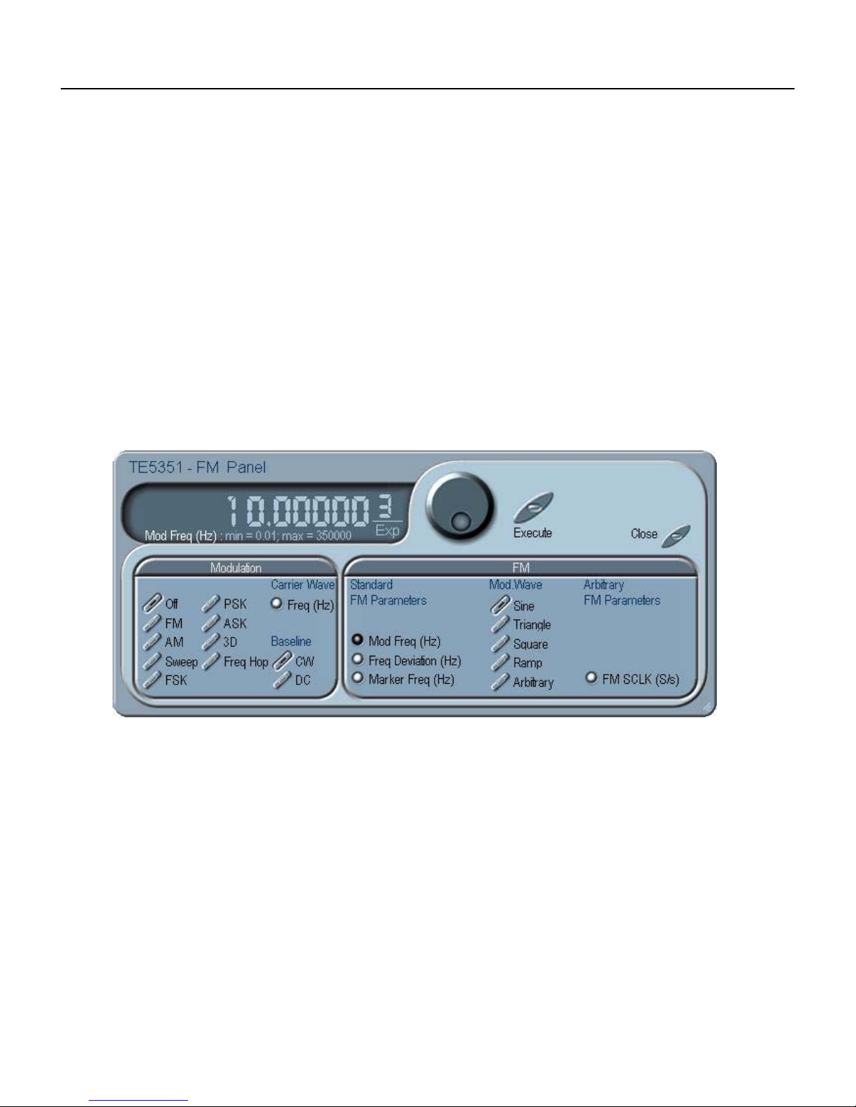
TE5251
User Manual
other hand, you can select the arbitrary modulating wave option
where you can use any shape however, you must load the
modulating waveform from an external application, such as the FM
composer in ArbConnection. Click on the button next to the required
modulating waveform shape to select it.
Arbitrary FM Parameters
Allow adjustment of the sample clock of the modulating waveform.
The shape of the modulating waveform must be downloaded from
an external utility such as ArbConnection and the sample clock is
programmed from this location.
To change the FM parameters, point and click on the required
parameter. The value that is associated with the lit LED is displayed
on the digital display. You can use the dial, keyboard, or the [↑] [↓}
keys to adjust the readout to the required setting. After you modify
the reading, press Execute to complete the process.
AM
The AM group contains parameters for controlling the frequency
modulation function. To turn the AM function on and off, click on the
FM button in the Modulation group. The various controls in the AM
group are described below.
Mod Wave
There is a list of 4 waveforms that can be selected to modulate the
carrier waveform (CW). These are sine, triangle, square and ramp.
The frequency and amplitude of the modulating waveforms are
programmable
Freq
Programs the frequency of the modulating waveform. Note that the
frequency setting must be smaller than the CW frequency for the
AM function to operate correctly.
3-22
Figure 3-13, the FM Panel
Page 75
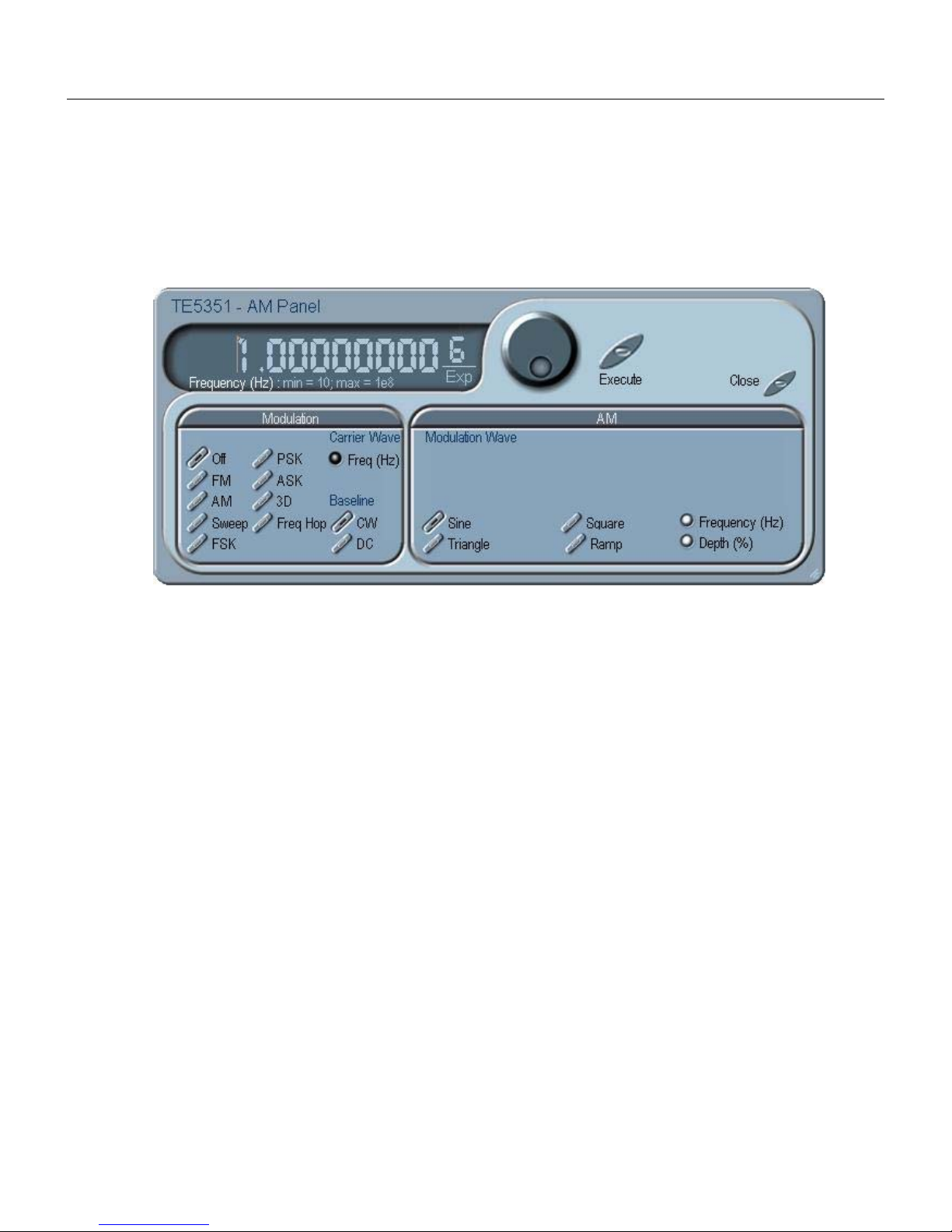
Depth
The Depth parameter programs the modulation depth, or index in
percent of the un-modulated CW amplitude. The depth is
symmetrical about the center of the CW amplitude.
ArbConnection
The Control Panels
3
Sweep
Figure
The Sweep group contains parameters for controlling sweep
options. To turn the Sweep function on and off, click on the SWP
button in Modulation group. The various parameters that control
sweep features are described below.
Step
Use these keys to select sweep step from two increment options:
linear, or logarithmic.
Direction
Use these keys to program sweep direction. Up select sweep from
Start to Stop sample clock setting and Down selects sweep from
the Stop to Start sample clock setting.
Parameters
Allow adjustment of Sweep Start, Stop and Sweep Time. You can
also place a marker at a position programmed by the Mark
parameter. To access the required parameter, click on the button
below parameters sub-group until the LED next to the required
parameter turns on. The value that is associated with the lit LED is
displayed on the digital display. You can use the dial, keyboard, or
the [↑] [↓} keys to adjust the readout to the required setting. After
you modify the reading, press Execute to update the 5251 with the
new setting.
3-14, the AM Panel
3-23
Page 76

TE5251
User Manual
ASK/FSK/PSK
Figure
3-15, the Sweep Modulation Panel
The ASK/FSK/PSK panel contains parameters for controlling the
ASK, FSK and the PSK functions. To select the required function,
click on the appropriate button and adjust the parameters in the
associated group. The various controls in the ASK/FSK/PSK groups
are described below.
ASK
Control Data
The Control Data button in the ASK group provides access to the
data string that controls the sequence of base amplitude and shifted
amplitude. It contains a list of “0” and “1” and the output will
repeatedly follow the amplitude shift keying sequence in the same
order as programmed.
“0/1” Amplitude
In ASK, the carrier waveform (CW) has two amplitudes: an initial
amplitude level which is set by the “0” Amplitude parameter and
shifted amplitude which is set by the “1” Amplitude. The control data
table has a list of “0” and “1” values that flag when the amplitude
shifts from base to shifted amplitudes.
Baud
The baud parameter sets the rate of which the generator steps
through the sequence of the ASK Control Data bits.
Marker Index
The marker setting programs a specific step (index) in the control
data string to output a pulse at the SYNC output connector. The
SYNC State button must be turned on to generate the ASK marker
output.
3-24
Page 77
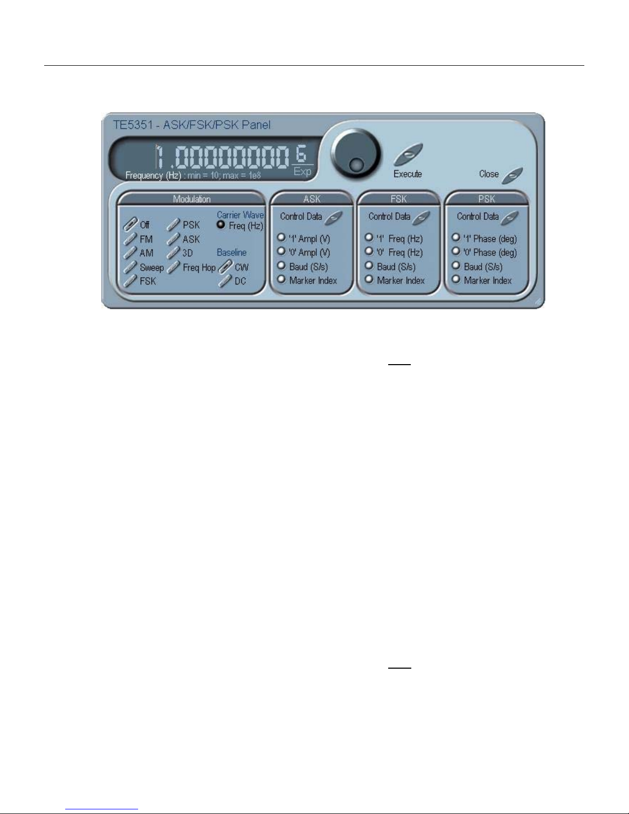
ArbConnection
The Control Panels
3
Figure
3-16, the ASK/FSK/PSK Modulation Panel
FSK
Control Data
The Control Data button in the FSK group provides access to the
data string that controls the sequence of base frequency and shifted
frequency. It contains a list of “0” and “1” and the output will
repeatedly follow the frequency shift keying sequence in the same
order as programmed.
“0/1” Frequency
In FSK, the carrier waveform (CW) has two frequencies: an initial
frequency level which is set by the “0” Frequency parameter and
shifted frequency which is set by the “1” Frequency. The control
data table has a list of “0” and “1” values that flag when the
frequency shifts from base to shifted frequency.
Baud
The baud parameter sets the rate of which the generator steps
through the sequence of the FSK Control Data bits.
Marker Index
The marker setting programs a specific step (index) in the control
data string to output a pulse at the SYNC output connector. The
SYNC State button must be turned on to generate the FSK marker
output.
PSK
Control Data
The Control Data button in the PSK group provides access to the
data string that controls the sequence of base phase and shifted
phase. It contains a list of “0” and “1” and the output will repeatedly
follow the phase shift keying sequence in the same order as
programmed.
3-25
Page 78

TE5251
User Manual
“0/1” Phase
In PSK, the carrier waveform (CW) has two phase settings: an initial
phase which is set by the “0” Phase parameter and shifted phase
which is set by the “1” Phase. The control data table has a list of “0”
and “1” values that flag when the phase shifts from base to shifted
phase.
Baud
The baud parameter sets the rate of which the generator steps
through the sequence of the PSK Control Data bits.
Marker Index
The marker setting programs a specific step (index) in the control
data string to output a pulse at the SYNC output connector. The
SYNC State button must be turned on to generate the PSK marker
output.
To access the required parameter, click on the button below
parameters sub-group until the LED next to the required parameter
turns on. The value that is associated with the lit LED is displayed
on the digital display. You can use the dial, keyboard, or the [↑] [↓}
keys to adjust the readout to the required setting. After you modify
the reading, press Execute to update the 5251 with the new
reading.
Frequency Hop
The Frequency Hop panel contains parameters for controlling
frequency hop options. To turn the frequency hop functions on and
off, click on the Freq Hop button in the Modulation group. The
various parameters that control frequency hop features are
described below. The output has two hop options: Fixed and
Variable. In the Fixed mode, the output steps through the preassigned hop values at a constant rate, as programmed using the
dwell time parameter. In the variable mode, the output dwells on
each step for a period of time that is programmed in the Dwell
Time field in the hop data table that is programmed for the Variable
Hold option.
Hop Data
The Hop Data button in the Freq Hop group provides access to the
data string that controls the sequence of frequency hops. The hop
data table contains a list of frequencies and the output will step from
one frequency to another in the same order as programmed in the
hop data table.
Fixed Hold
The hold parameter determines how long will certain step of
frequency dwells on this specific setting before it will step to the
next frequency setting. By selecting the Fixed Hold, the hold time
remains constant throughout the entire hop table.
3-26
Page 79
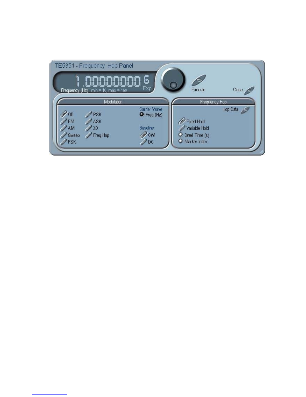
ArbConnection
The Control Panels
3
Figure
Variable Hold
The hold parameter determines how long will certain step of
frequency dwells on this specific setting before it will step to the
next frequency setting. By selecting the Variable Hold, the hold time
changes automatically from one step to the next, depending on the
hold time value that is affixed to the hop step. The values can be
programmed in the HOP Data table.
Dwell Time
The Dwell Time parameter programs the period of time that will
lapse before the frequency hops to the next frequency setting. The
Dwell time is associated with the Fixed Dwell option only.
Marker Index
The marker setting programs a specific step (index) in the hop data
string to output a pulse at the SYNC output connector. The SYNC
State button must be turned on to generate the hop marker output.
To access the required parameter, click on the button below
parameters sub-group until the LED next to the required parameter
turns on. The value that is associated with the lit LED is displayed
on the digital display. You can use the dial, keyboard, or the [↑] [↓}
keys to adjust the readout to the required setting. After you modify
the reading, press Execute to update the 5251 with the new setting.
3-17, the Frequency Hop Panel
3-27
Page 80

TE5251
User Manual
The Auxiliary
Panels
The Auxiliary tab provides access to a group of panels that control
some auxiliary and Utility functions.
There are six panels in this group: Counter/Timer, which provides
access to the auxiliary Counter/Timer function; Pulse Generator,
which provides access to the auxiliary digital pulse generator
function; and Half Cycle, which provides access to the half cycle
functions.
The Auxiliary set of panels is shown in Figure 3-18. Each of the
panels is described below.
Counter/Timer
Figure 3-18, the Auxiliary Panels
The Counter/Timer panel contains controls that select the
measurement function and adjusts the counter/timer parameters
for measuring external signals. The counter/timer measures
signals that are connected to the TRIG IN input. The various
parameters that control the counter/timer features are described
below.
State
The State Group has controls to turn the counter on and off. And to
reset the counter and arm it for the next measurement cycle. Note
that when the counter function is turned on, all other waveform
generation features of the 5251 are purged.
Measurement Function
The measurement function group has control to select the
measurement function for the counter/timer operation. The 5251
can measure the following function: Frequency, Period, Period
Averaged, Pulse Width, and Totalize. The totalize function has two
options. If Totalize Infinite function is selected the input will count
every legal pulse at the counter input, for an indefinite period of
time, and will display the total number of pulses until the counter
has been reset. If Totalize Gated function is selected, the input will
count every legal pulse at the trigger input for a period of time that
is defined with the Gate Time parameter.
3-28
Page 81

ArbConnection
The Control Panels
3
Figure 3-19, the Counter/Timer Panel
Display
The Display Group has controls to select the display mode and to
select if the display shows measurement or gate time readings.
In normal mode, the counter is armed to receive signal at the trigger
input. When signal is sensed, the gate to the counter opens for
duration as programmed with the Gate Time parameter, processes
the result, displays the reading and continues with the same
process as long as the signal is available at the input.
In hold mode, the counter is armed to receive signal at the trigger
input. When signal is sensed, the gate to the counter opens for
duration as programmed with the Gate Time parameter processes
the result, displays and holds the reading until the next Reset/Arm
command.
To display and modify the gate time parameter, click on the Gate
Time LED and modify the gate time per your requirements. Gate
time rage is from 100 μs to 1 s. Normal counter/timer readings are
displayed when the Reading LED is selected.
3-29
Page 82
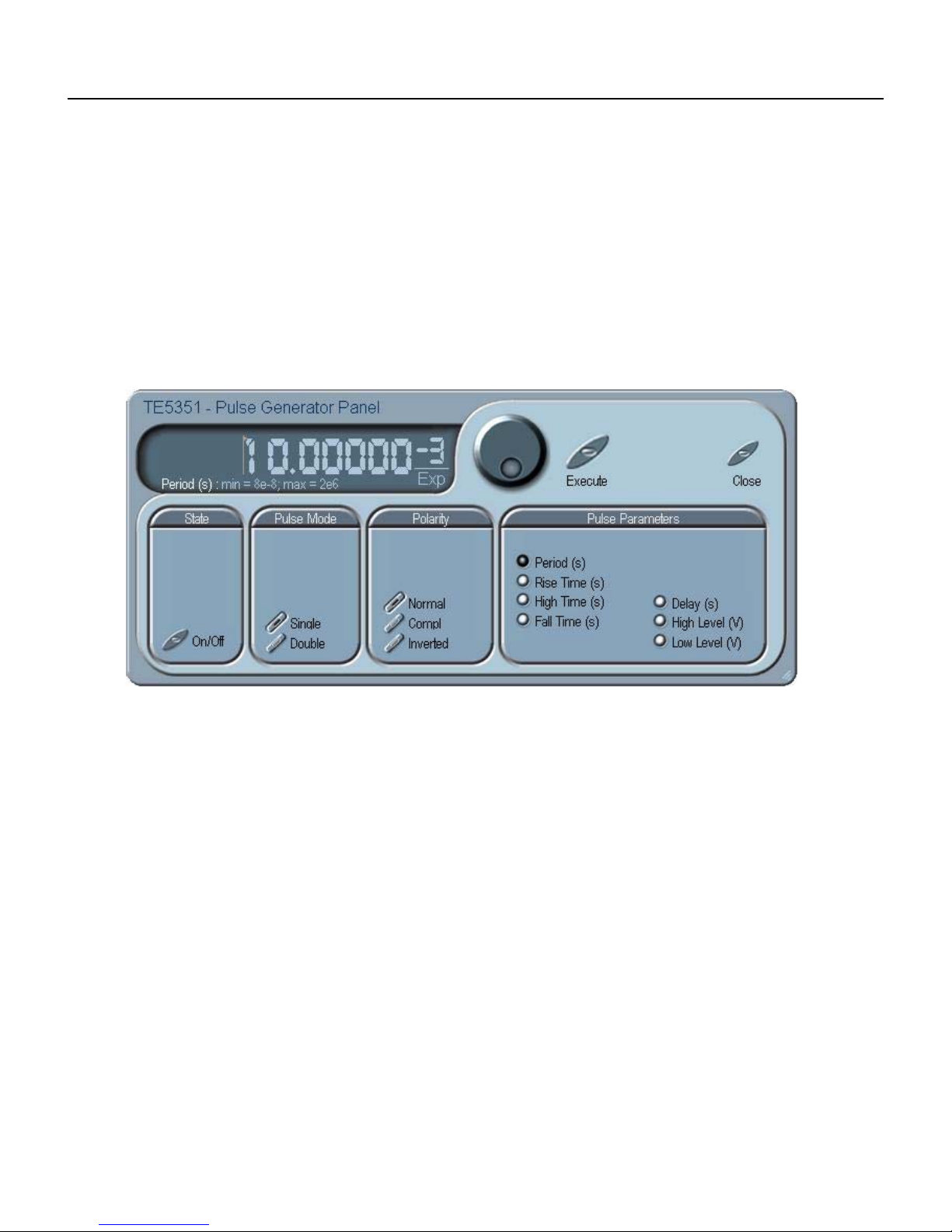
TE5251
User Manual
Pulse Generator
The Pulse Generator panel contains controls that select the pulse
function and adjusts the pulse parameters. The pulses are
generated digitally suing the arbitrary waveform memory and digital
computation and therefore, there are some limitations to the
minimum to maximum range that must be observed. The pulse
design limitations are given in Appendix A. The various parameters
that control the digital pulse generator features are described
below.
Figure 3-20, the Digital Pulse Generator Panel
Pulse Mode
The Pulse Mode group has controls to turn on pulse generator
functions, select of the output generates single or double pulse
shape and selects the pulse polarity from one of the Normal,
Complemented and Inverted options.
Polarity
The Polarity group has controls to select between Normal,
Complemented and Inverted pulse shapes.
Pulse Parameters
In the pulse parameters group you adjust the complete set of
parameters that builds up the pulse shape. Included are: period,
rise and fall times, high time delay and high and low amplitude
levels.
To display and modify parameters, click on the and next to the
required parameter change and modify time per your requirements.
The range of each parameter is specified in Appendix A.
3-30
Page 83

ArbConnection
The Control Panels
3
Half Cycle
The Half Cycle panel contains controls that select the half cycle
functions and adjust the half cycle parameters.
The half cycle functions are generated with variable and
controllable delay between the halves. If triggered mode, one half
at a time is generated as a result of a trigger signal regardless of
the programmed delay value. The half cycle functions have
different limitations compared to the standard functions; These are
listed in Appendix A. The half cycle panel and the various
parameters that control these functions are described below.
Figure 3-21, the Half Cycle Panel
Shape
The shape group has controls that select the shape of the half cycle
function. You may select from sine, triangle and square shapes. If
you do not modify the start phase parameter, the half cycle sines
and triangles will start from phase 0° and will stop at phase 180°.
The second half cycle will commence at the end of the time interval
that is programmed with the delay parameter.
Parameters
The parameters group has parameters that control frequency,
amplitude, offset and delay. In this group, you can also program
the sine and triangle start phase and the duty cycle of the square
waveform.
Note that the frequency value is a bit different than the standard
frequency parameter because it describes the frequency as if the
two halves were combined (which is never the case). Since two
halves are always separated by certain delay, the frequency value
has a meaning as if the two halves were truncated.
3-31
Page 84

TE5251
User Manual
The System Panels
The System tab provides access to a group of panels that control
some general system parameters and provides access to the
calibration. There are two panels in this group: General/System,
which provides access to some system commands, utilities and
filters; and Calibration, which provides access to the calibration
remote calibration utility. Note however, that access to the
calibration panel is permitted to qualified service persons and
requires special user name and password. Information how to
access the calibration panel is given in Adjustments and Software
Updates chapter.
The System set of panels are shown in Figure 3-22. Each of the
panels is described below.
General/Filters
Figure 3-22, the System Panels
The General/Filters panel provides access to some general system
common commands, allows read back of information that is stored
in the flash and provides means of adding filters to the output path.
The General/Filters panel is shown in Figure 3-23 and the various
parameters that control these functions are described below.
System
The System group has three buttons that are normally associated
with system control. These are:
Reset – generates soft reset to the instrument controls and dialog
boxes and modifies all parameters to factory default. A list of factory
defaults is given in the programming chapter of this manual.
Query Error – queries the 5251 for programming errors. This
command is normally no necessary because ArbConnection makes
sure that programming errors cannot be made from the panels
however, while executing commands from the Command Editor,
errors can be generated and the only way to monitor the errors is by
using this command.
3-32
Page 85

ArbConnection
The Control Panels
3
Figure 3-23, the General/Filters Panel
Clear Queue – clears the error queue. The error queue can buffer
up to 35 errors and then generates an error queue overflow
message while ignoring new errors. This command clears the error
queue and allows fresh errors to be captured.
General Information
This General Information group is used for displaying or monitoring
of certain parameters that are stored in the flash memory. These
are: Instrument serial number and last calibration date. You can
also read the installed firmware revision, in case you want to verify
that you have the latest firmware revision.
Filters
The filters can be turned on and off freely as long as you are not
generating the standard sine waveform. The following filter options
are available:
Off – no filter is applied to the output path
25MHz – a Bessel type filter that has 25 MHz cutoff frequency.
50MHz – a Bessel type filter that has 50 MHz cutoff frequency.
60MHz – an Elliptic type filter that has 60 MHz cutoff frequency.
120MHz – an Elliptic type filter that has 120 MHz cutoff frequency.
Calibration
The Calibration panel, as shown in Figure 3-24, provides access to
remote calibration procedures. To access the remote calibration
panel, you will need to have a valid User Name and Password and
to quality to perform such calibration, you’ll need to be trained and
certified by Tabor Electronics. Information how to access the
calibration panel and how to perform the calibration is given in the
adjustment and firmware updates chapter. The picture below is just
for reference how the calibration panel will look after you gain
access to this panel.
3-33
Page 86

TE5251
User Manual
Figure 3-24, the Calibration Panel
The Composers
Panels
The Composers tab provides access to a group of composers that
allow generation and editing of arbitrary waveforms, pulse shapes,
arbitrary frequency modulation and 3D profiling. Without utilities
such as the above, the operation of an arbitrary waveform
generator is extremely limiting.
There are four waveform composers built into ArbConnection:
Wave – for generating arbitrary waveforms. Arbitrary waveforms
can be generated from standard libraries, from an equation editor,
or imported to the composer from external utilities such as MatLAB.
The waveforms can be edited and stored on hard or soft disks.
Pulse – for generating complex pulse trains. Unlike a standard
pulse generator, you can design and edit multiple pulse trains with
linear transitions and variable amplitudes.
FM – for generating frequency modulation schemes. Unlike a
standard frequency modulator, you can design and edit your own
frequency modulation profiles.
3D – for generating simultaneous sweeps of amplitude, frequency
and phase. This is specifically useful for generating complex chirps.
The Composers set of panels are shown in Figure 3-25. Each of the
composers is described below.
3-34
Page 87
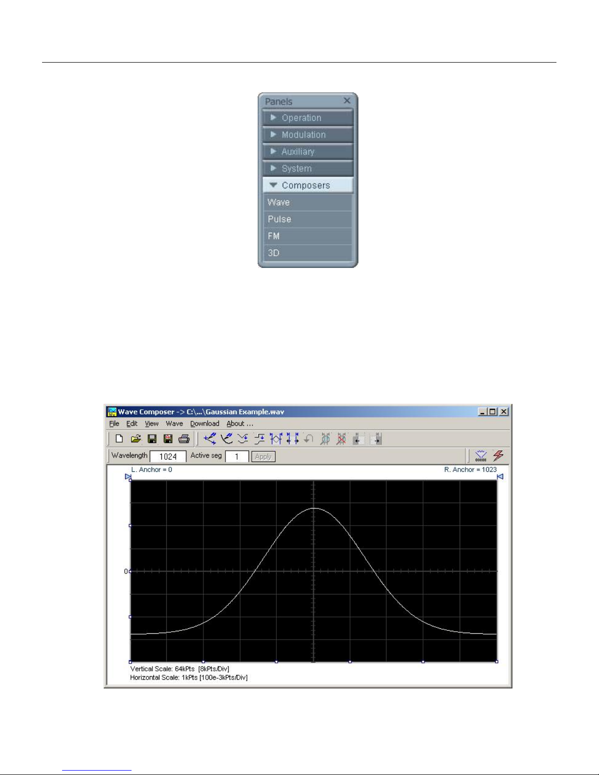
ArbConnection
The Control Panels
3
Figure 3-25, the Composers Panels
The Wave Composer
Being an arbitrary waveform generator, the 5251 has to be loaded
with waveform data before it can start generating waveforms. The
waveform generation and editing utility is part of ArbConnection and
is called – The Waveform Composer.
Figure 3 3-26, the Wave Composer Opening Screen
3-35
Page 88

TE5251
User Manual
The Commands bar
This program gives you tools to create definitions for arbitrary
waveforms. It can also convert coordinates from other products,
such as, oscilloscopes and use them directly as waveform data.
The program is loaded with many features and options so use the
following paragraphs to learn how to create edit and download
waveforms to the 5251 using the Waveform Composer.
To launch the wave composer point and click on the Wave tab in
the Panels bar. Figure 3-26 shows an example of the wave
composer. The Wave Composer has main sections: Commands
bar, Toolbar and Waveform screen. Refer to Figure 3-26 throughout
the description of these sections.
The commands bar provides access to standard Windows
commands such as File and View. In addition, there are
ArbConnection-specific commands such as Edit, Wave and
System.
In general, clicking on one of the commands opens a dialog box
with an additional list of commands. Then, clicking on an additional
command, may open a dialog box, or generate an immediate
action. For example, Clicking on File and then Exit will cause an
immediate termination of the Wave Composer. On the other hand,
clicking on Wave and then on Sine, will open a Sine Wave dialog
box that lets you program and edit sine wave parameters. The
various commands in the Commands bar are listed and described
below.
File Commands
3-36
The File command has 4 command lines that control waveform
files. Also use this command to print the active waveform, or exit
the wave composer program. Description of the various commands
under File is given below.
New Waveform
The New Waveform (Ctrl+N) command will remove the waveform
from the screen. If you made changes to the waveform area and
use the New Waveform command, you should save your work
before clearing the screen. The New Waveform command is
destructive to the displayed waveform.
Open Waveform…
The Open Waveform… (Ctrl+O) command will let you browse your
disk for previously saved waveform files and load these waveforms
to the waveform area. This command is also very useful for
converting waveform files to format that is acceptable by the Wave
Composer. The Open Waveform command can convert ASCII.
Page 89

*CSV (comma delimited text), *PRN (space delimited text) and *.0*
(LeCroy binary format). The Open dialog box in Figure 3-31 shows
the various file extensions that can be opened into the Wave
Composer environment. The file that is opened is automatically
converted to *.wav format and can later be saved as a standard
ArbConnection file.
Save Waveform
The Save Waveform (Ctrl+S) command will store your active
waveform in your 5251 directory, as a binary file with an *.wav
extension. If this is the first time you save your waveform, the Save
Waveform As… command will be invoked automatically, letting you
select name, location and format for your waveform file.
Save Waveform As…
Use the Save Waveform As… command the first time you save
your waveform. It will let you select name, location and format for
your waveform file.
Print
With this command you may print the active Waveform Window.
The standard printer dialog box will appear and will let you select
printer setup, or print the waveform page.
ArbConnection
The Control Panels
3
Figure 3-27, the Open Waveform Dialog Box
Exit
The Exit command ends the current Wave Composer session and
takes you back to the Panels screen. If you made changes to your
waveform since it was last saved, the Wave Composer will prompt
you to Save or Abandon changes these changes.
3-37
Page 90

TE5251
User Manual
Edit Commands
The Edit commands are used for manipulating the waveform that is
drawn on the screen. The editing commands are explained in the
following paragraphs.
Autoline
The Autoline command lets you draw straight-line segments. To
draw a line the left mouse button at the start point. Click again at
the next point and then click on the right mouse button to terminate
this operation.
Sketch
The Sketch command lets you draw free-hand segments. To draw a
line using this command click and hold the left mouse button at the
start point. Release the mouse button when you want to stop and
then click on the right mouse button to terminate this operation.
Smooth
The Smooth command lets you smooth out rough transitions on
your waveform. This is done mathematically by multiplying
waveform coordinates by the non-linear portion of a cubic parabola.
The Smooth operation is done on segments of the waveform that
are bound by anchors. Anchor operation is described later in this
chapter. Place the anchors on the left and right of your waveform
segment and select the Smooth command. The waveform will
change its shape immediately to follow the mathematical pattern of
a parabolic curve.
Note that small segments with fast transitions, when combined with
parabolic expressions have tendencies to generate even larger
transitions. Therefore, make sure you omit such sections of the
waveform when you use this operation.
Filter
The Filter used with this command is moving average. This is done
by recalculating each point as an average of symmetrical number of
adjacent points. When you select the Filter command, a dialog box
pops up, letting you program the filter spacing in number of
adjacent points. You can filter the entire waveform, or you may
chose to filter a segment of the waveform by placing the anchors as
boundaries on the left and right of the segment.
Invert
The Invert command lets you invert the entire waveforms, or
marked segments of waveforms. The waveform is inverted about
the 0-point axis.
Trim Left
The trim left command lets you trim waveforms to the left of the
anchor point. This command is grayed out if the left anchor was not
moved from its original left position. The waveform is trimmed and
the point at the left anchor point becomes the first point of the
waveform.
3-38
Page 91

Trim Right
The trim right command lets you trim waveforms to the right of the
anchor point. This command is grayed out if the right anchor was
not moved from its original right position. The waveform is trimmed
and the point at the right anchor point becomes the last point of the
waveform.
Unmark
The unmark command removes the anchors from the waveform
screen and resets anchor positions to point 0 and the last waveform
point.
Undo
The Undo command undoes the last editing operation.
ArbConnection
The Control Panels
3
View Commands
The View commands have commands that let you view various
sections of the waveform area. The View commands include: Zoom
In, Zoom Out, Hide/Show Toolbars and Channel 1 to 4 waveforms.
Description of the view commands is given in the following.
Zoom In
The zoom in command operates between anchors. Anchors are
marked as left and right hand triangles. The default position of the
anchors is the start and the end of the waveform. To move an
anchor to a new location, click and hold on the triangle and drag the
anchor to left or right as required. If you move the left anchor to the
right and the right anchor to the left, the area between the anchors
will zoom in as you select this command.
Looking at the Waveform Map, as shown in Figure 3-28, you’ll see
that the white portion is the zoomed area. Click and hold on the
white area and move your cursor around and the waveform screen
will be updated accordingly.
While zoomed in you can perform Autoline and sketch editing, or
zoom-in further by clicking and holding the mouse at one corner
and releasing the mouse button at the other corner.
Zoom Out
The zoom out restores the screen to display the complete
waveform.
3-39
Page 92

TE5251
User Manual
Wave Commands
Figure 3-28, Zooming In on Waveform Segments
The Wave commands let you create waveforms on the screen. The
Wave command has a library of 8 waveforms: Sine, Triangle,
Square, Sinc, Gaussian, Exponent, Pulse, Noise and dc. Also, from
the Wave command, you can create Cardiac waveforms and pulse
width modulation. Finaly, custom waveforms are created using the
Equation Editor. Information how to create waveforms using the
Wave commands is given below.
Creating Waveforms From the Built-in Library
You can create any waveform from the built-in library using the
Wave command. Clicking on one of the Wave options will open a
dialog box. An example of the Sine waveform dialog box is shown
in Figure 3-29. This dialog box is representative of the rest of the
waveforms, so other waveforms will not be described.
Creating Sine Waveforms
Use the following procedure to create sine waveforms from the
built-in library. Click on Wave, then sine… the dialog box as shown
in Figure 3-29 will appear. You can now start programming
parameters that are available in this box.
Start Point – Defines the first point where the created wave will
start. Note that if you change the start point the left anchor will
automatically adjust itself to the selected start point. The example
shows start point set at point 0.
3-40
Page 93

End Point – Defines where the created waveform will end. Note that
as you change the end point the right anchor will automatically
adjust itself to the selected end point, 499 shown in the example.
Cycles – The Cycles parameter defines how many sine cycles will
be created within the specified start and end points. The example
below shows five sine cycles.
Amplitude – 16-bit of vertical define 32,768 incremental steps. The
Amplitude parameter defines how many of these steps are used for
generating the sine. The example is showing sine waveform with
maximum peak-to-peak amplitude. Any number below the
maximum will generate an attenuated sine.
Start Phase – The start phase parameter defines the angle of which
the sine will start. The example shows start phase of 90°.
Power – The example shows sine cubed. Sine to the power of 1 will
generate a perfect sine. Power range is from 1 through 9.
ArbConnection
The Control Panels
3
Figure 3-29, Generating Distorted Sine waves from the built-in Library
The Toolbar
The toolbar contains icons for editing the waveform screen, icons
for saving and loading waveforms, fields for selecting an active
channel and for adjusting segment length and more. The Toolbar is
shown in Figure 3-30. For the individual icons, refer to the
descriptions above of the Wave Composer Menus.
3-41
Page 94
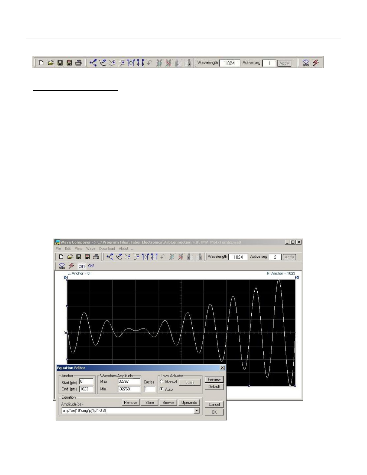
TE5251
User Manual
Figure 3-30, the Toolbar Icons
The Waveform
Screen
Waveforms are created and edited on the waveform screen. Figure
3-35 shows an example of a waveform created using the equation
editor and the anchors to limit generation of the waveform between
points 100 and 900. The various elements of the waveform screen
are described below.
The waveform screen has two axes – vertical and horizontal. Both
axes are divided into points.
The vertical axis is labeled from -32,767 through 32,768 for a total
of 65,536 point (includes point “0”). This number represents 16 bits
of vertical resolution and cannot be changed because it is critical to
the range of which the 5251 operates.
The horizontal axis, by default has 1000 points (from point 0 to
999). This number can be changed using the Wave Length field in
the Toolbar. The maximum length depends on the option installed
in your instrument. The wave composer will let you define the
horizontal axis to a maximum of 2M words).
3-42
Figure 3-31, the Waveform Screen
Page 95
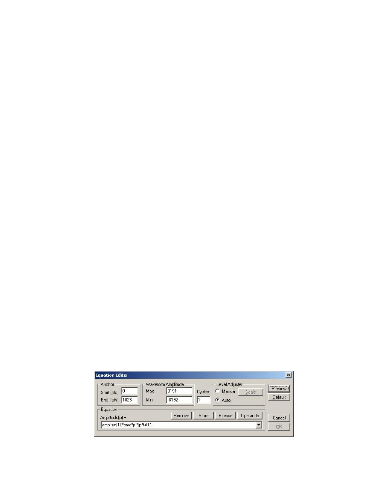
Generating Waveforms Using the Equation Editor
ArbConnection
3
Notice on the left top and on the right top there are two triangles
pointing to the center of the screen. These are the anchors. The
anchors are used as the start and end pointers where your
waveform will be created. For example, if you want to create a sine
waveform between point 100 and point 500, you place the left
anchor at point 100 and the right at point 500 and then generate the
sine from the built-in library.
There are two ways to control anchor placements.
1) Click and hold your mouse cursor on the left anchor triangle and
then drag the curtain to the left position. Do the same for the
right anchor. Notice the X and Y coordinates at the top of the
waveform screen and how they change to correspond to your
anchor placement.
2) You can also place your anchors in a more precise manner from
the waveform library by programming the start and end points
for the waveform. An example of anchor placement using the
sine dialog box is shown in Figure 3-29.
Finally, when you are done creating and editing your waveform, you
can save your work to a directory of your choice. The name at the
title will show you the name you selected for storing your waveform
and its path.
Generating
Waveforms Using
the Equation
Editor
One of the most powerful feature within ArbConnection and
probably the feature that will be used most is the Equation Editor.
The Equation Editor let you write equations the same way as you
would do on a blank piece of paper. The equations are then
translated to sequential points that form waveforms and are
displayed on the waveform screen. The Equation Editor will detect
and inform you on syntax errors and, with its self adjusting feature,
will automatically adjust your parameters so that none of the points
on your waveform will exceed the maximum scale limits.
When you invoke the Equation Editor, the dialog box, as shown in
Figure 3-32 will display. Use the following paragraphs to learn how
to use this dialog box and how to write your equations.
Figure 3-32, the Equation Editor Dialog Box
3-43
Page 96

TE5251
User Manual
There are four sub-group parameters in the equation editor plus
control buttons and equation field. These parts are described below.
Anchor
The anchors define start and end point of which the equation will be
generated. By default the anchors are placed at the start and the
end of the horizontal (time) scale however, the equation can be
limited to a specific time scale by moving the anchor points from
their default locations.
Start – defines the first point where the created wave will start. Note
that if you change the start point the left anchor will automatically
adjust itself to the selected start point.
End – defines where the created waveform will end. Note that as
you change the end point the right anchor will automatically adjust
itself to the selected end point.
Waveform Amplitude
The vertical axis of the Wave Composer represents 14-bits of
vertical resolution. That means that the equation is computed,
resolved and generated with 1/32,768 increments and accuracy.
The Waveform Amplitude fields in the Equation Editor are used in
two cases: 1) when the “amp” parameter is used in the equation or
2 if the Level Adjuster is set to Auto. Information on these two
operations is given later.
Max – defines the positive peak of the vertical axis
Min – defines the negative peak of the vertical axis
Cycles
The Cycles parameter defines how many waveform cycles will be
created within the specified start and end anchor points.
Level Adjuster
The Level Adjuster is a convenient tool that helps you adjust the
amplitude and offset without modifying your equation. The Level
Adjuster mode does not interfere with your calculations and
displays the waveform as computed from your equation. The only
difference is that your final calculations are stretched or shrunk or
offset on the vertical scale to fit the new amplitude and offset
boundaries.
If you change the Max and Min setting in the Waveform Amplitude
fields and press the Adjust key, your waveform will offset
immediately without changing the equation. The same way, you can
also change amplitude only or both amplitude and offset. If you
check the Manual option, you’ll have to click on the Adjust button for
the Waveform Amplitude parameters to take effect. The Adjust
button name will change to Restore and back to Adjust if you click
on it again. If you check the Auto option, your waveform will be
created automatically with the new Amplitude setting.
3-44
Page 97

Equation
The Equation group has four buttons and the equation field. You will
be using the Equation field for writing your equations. Equation
syntax and conventions are discussed in the following paragraphs.
The Remove button clears the equation field so you can start typing
a new equation. Click on the Store button to store your equation if
you intend to use it again. The Browse button provides access to
waveform pre-stored files in your computer for combining them in
new equations. The Operands button expands the bottom of the
dialog box to show the operands you can use with your equation.
While you type and store equations, they are collected in a history
file and can be used again by expanding the history log from the
equation field.
Control Buttons
There are four control buttons at the right corner of the dialog box.
Use the Preview button to preview an image of your equation, or
use the OK button to place your waveform on the waveform screen
and to leave the dialog box on the screen. The Default button
restores the parameters in the equation editor to their original
factory default values. The Cancel button will remove the dialog box
from the screen and will discard of any waveforms that you
previewed with your Equation Editor.
Generating Waveforms Using the Equation Editor
ArbConnection
3
Writing Equations
The Equation Editor lets you process mathematical expressions
and convert them into waveform coordinates. As you probably
already know, waveforms are made of vertical samples. The
number of samples on your waveform is determined by the
wavelength parameter. For example, if you have 1024 horizontal
points, your equation will be computed along 1024 points as a
function of the vertical scale. Each vertical sample is computed
separately and placed along the horizontal axis. The points are
graphically connected to form a uniform and continuous waveform
shape however, if you zoom in on a waveform line, you’ll see that
the points are connected like a staircase. In reality, the 5251
generates its waveforms exactly as shown on the screen but, if the
waveform has many horizontal points, the steps get smaller and
harder to see without magnification.
Equations are always computed as a function of the vertical
(Amplitude) axis therefore the left side of your equation will always
look as Amplitude(p)=, where “p” is the equation variables in units of
waveform points. You can write equations with up to 256
characters. If the equation is too long to fit in the visible field, parts
to the left or right will scroll off the ends.
3-45
Page 98

TE5251
User Manual
Equation
Convention
The following paragraphs describe the conventions that are used
for writing an equation. To avoid errors, it is extremely important
that you make yourself familiar with these conventions before you
plan your waveforms.
Equations are written in conventional mathematical notation. You
may only enter the right part of the equation. The only limitation is
that the equation must be of a single variable that is directly related
to the current horizontal axis setting. Case is not important and
spaces are ignored. Numbers are entered in scientific notation. All
calculations are done with double-digit precision. For the
trigonometric functions, all angles are expressed in radians.
A number of constants are provided: e, which is the base of the
natural logarithm; pi, which is the circumference of a unit-diameter
circle; per, which equals the programmed horizontal range; f, which
equals 1 /per; omg, which equals 2 * pi / per, and numerals in the
range of -1E^20 to 1E^20.
There are three classes of precedence: ^ (raise to power) has the
highest precedence; (multiply) and / (divide) come second; + and have the lowest precedence. Parentheses may be used to change
the order of precedence. The following table summarize the
mathematical expressions and their respective abbreviated
commands that can be used with the Equation Editor.
Equation Editor Operands
^ Raise to the power
* Multiply
/ Divide
+ Add
Ä Subtract
( ) Parentheses
e Base of natural Logarithm
pi (π) Circumference of unit-diameter circle
per Horizontal wavelength in points
f I/per
omg (Ω) 2*π / per
amp Amplitude in units of points or seconds
sin(x) The sine of x(*)
cos(x) The cosine of x
tan(x) The tangent of x
ctn(x) The cotangent of x
log(x) The base IO logarithm of x
In(x) The natural (base e) logarithm of x
abs(x) The absolute value of x
-1E^20<>1E^20 Numerals, equation constants
(* )x = argument mathematical expression
After you get familiar with the operands and conventions, you can
commence with a few simple equations and see what they do to
your waveform screen. Once you'll get the feel, you'll be able to
3-46
Page 99

explore your own creativity to generate much more complicated and
complex waveforms.
Generating Waveforms Using the Equation Editor
ArbConnection
3
Typing Equations
If you remember from your old high school studies, the simplest
curve of Y as a function of X is defined by the equation Y=aX+b.
You can use the same “technique” to generate straight lines with
the Equation Editor. Assuming first that p=0, try this:
Amplitude(p)=1000
Press [Preview] and see what you get. Of course, you get an
uninteresting line that runs parallel to the X-axis. Now, lets give the
line some angle by typing:
Amplitude(p)=-2*p+2000
Press [Preview] and see that the line slopes down. It may still be
not very interesting however, pay close attention to the convention
that is used in this equation. You cannot type: Amplitude(p)=2p+1000, like you would normally do in your notebook; You must
use the * (multiply) sign, otherwise you'll get a syntax error. Now
we'll try to generate a simple sine waveform. Try this:
Amplitude(p)=sin(10)
Press [Preview] and… sorry, you still get nothing on the screen.
The Wave Composer did not make a mistake! The sine of 10 in
radians is exactly what it shows. You are unable to see the result
because the line on your screen running across the 0 vertical point.
REMEMBER
The equation must be a function of a single variable and
that variable must be directly related to the Horizontal
axis Scale setting.
Now try this:
Amplitude(p)=sin(omg*p)
Still no good, but now press the [Adjust] button and here is your
sinewave. So what's wrong? Well, if you'll give it a little amplitude it
might help so, do it now exactly as follows:
Amplitude(p)=8000*sin(omg*p)
There you go. You should now see a perfect sine waveform with a
period of 1000 points. This is because you have asked the Equation
Editor to compute the sine along p points (“p” is the equation
variable, remember?). If you want to create 10 sine waveforms, you
should multiply p by 10. Try this:
Amplitude(p)=8000*sin(omg*p*10)
3-47
Page 100

TE5251
User Manual
Equation Samples
So far, you have learned how to create two simple waveforms:
straight lines and trigonometric functions. Let’s see if we can
combine these waveforms to something more interesting. Take the
straight line equation and add it to the sinewave equation:
Amplitude(p)=12000*sin(omg*p*l0)-8*p+4000
Press [Preview]. Your screen should look like Figure 3-33.
Figure 3-33, an Equation Editor Example
Now let’s try to modulate two sine waves with different periods and
different start phase. Type this:
Amplitude(p)= 12000*sin(omg*p)*cos(omg*p*30)
Press [Preview]. Your screen should look like Figure 3-34.
3-48
 Loading...