

Page 1
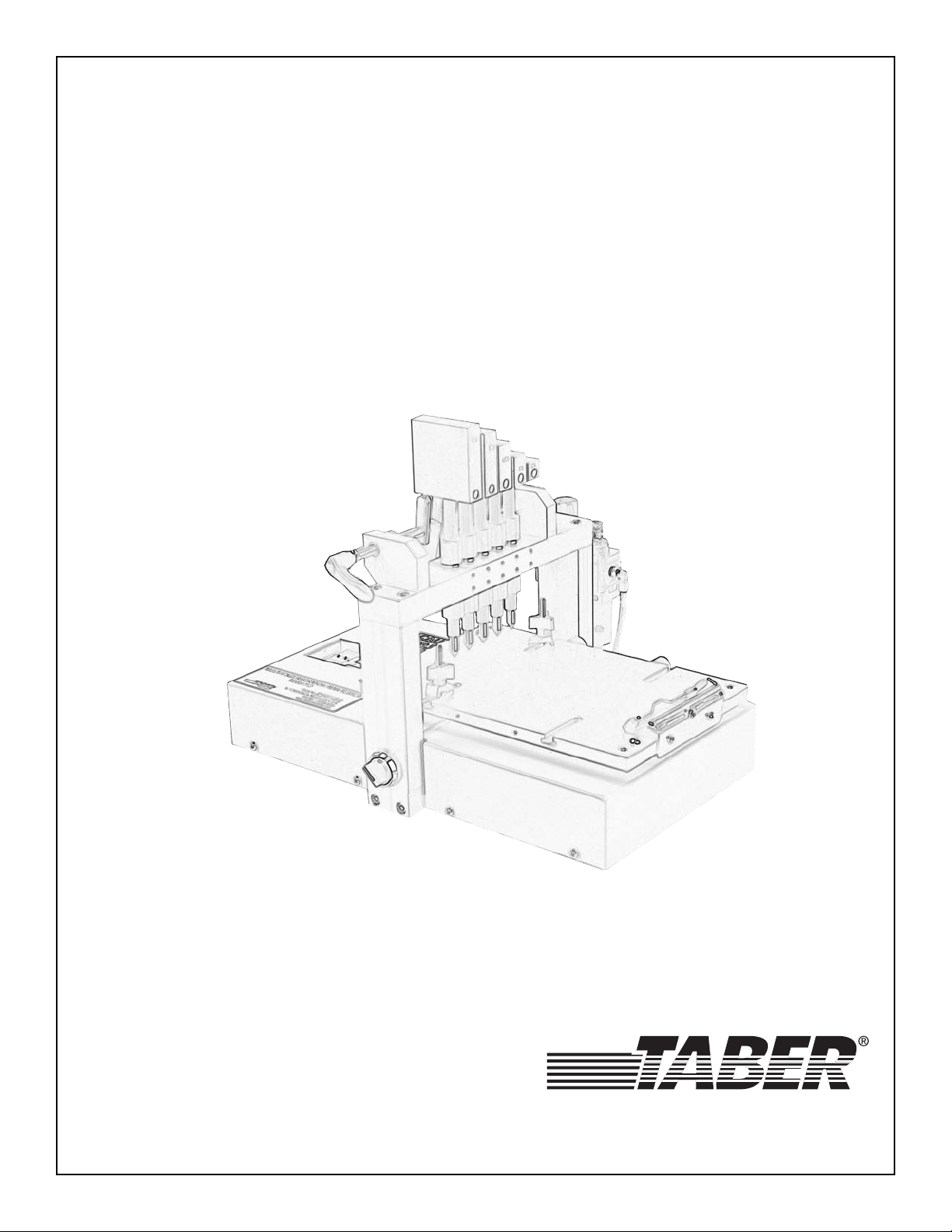
Multi-Finger
Scratch/Mar Tester
Model 710
Operating Instructions
INDUSTRIES
9001:2000ISO CERTIFIED
Page 2
WARRANTY
Any product or part which, under normal operating conditions in the facility of the original purchaser, proves defective in material or workmanship within one year from the date of shipment by
the company, as determined by an inspection by
Taber
®
Industries, will be repaired or replaced
free of charge provided you promptly return the
defective material. All claims must be sent to
Taber Industries with transportation charges prepaid, notice of the defect and verification the
product has been properly installed, maintained
and operated within the limits of rated and normal
usage.
Replacement parts will be shipped FOB our
plant. The terms of this warranty do not in any
way extend to any product or part thereof that
has a life, under normal usage, inherently shorter than the one-year indicated above. Said warranty in respect of replacement of defective parts
and any such additional warranty or representation expressly made, are in lieu of all other warranties expressed or implied, including any
implied warranty of merchantability, or fitness for
any particular purpose.
Taber Industries reserves the right to make
changes without notice at any time in colors,
material, specifications, and models, and to discontinue models.
CLAIMS FOR SHORTAGES
We use extreme care in selection, checking, and
packing to eliminate the possibility of error. If a
shipping error is discovered:
1. Carefully examine the packing materials and
ensure nothing was inadvertently overlooked
when the shipment was unpacked.
2. Notify the company you purchased the prod-
uct from and immediately report the shortage.
The materials are packed at the factory, and
should be complete if the box has not been
opened.
3. Claims should be filed within 30 days from
shipment.
CLAIMS FOR DAMAGES
Claims for loss or damage in transit should be
made promptly and directly to the transportation
company.
CONTENTS
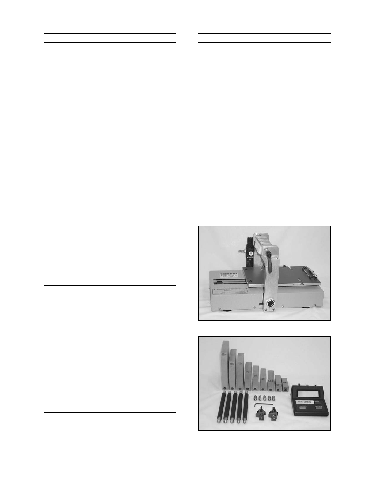
Contents of the shipping container should include
the following:
• Multi-Finger Scratch / Mar Tester
• Spline Shaft Finger Assembly (5 each)
• Scratch Tip, 1.0mm Diameter Hemisphere (5
each)
• Mar Tip, 7.0mm Diameter Hemisphere (5
each)
• 9 Piece Weight Set - 2N, 3N, 4.5N, 5N, 6N,
7N, 10N, 15N, 20N
• Electronic Timer with Digital Display
• Specimen Clamp with T-Slot Nut, Stud and
Thumb Nut (set of 2)
• Quick Disconnect Socket for Air Supply, with
female ¼" NPT thread
• 3/32" Hex Wrench
• Operating Instructions
1 710 Operating Instructions ver 1.1
Page 3
tion such that the scratch pin does not contact
the specimen during testing.
Individual weights of varying loads mount to the
top of each spline-shaft finger to exert a standard
force on the surface of the test material. The
standard 9-piece weight set includes loads that
range from 2N to 20N. Optional weights are
available to test up to 25N.
After lowering the scratch tips onto the specimen
surface, compressed air drives the platform
under the scratch tips to generate the damage on
the specimen surface.
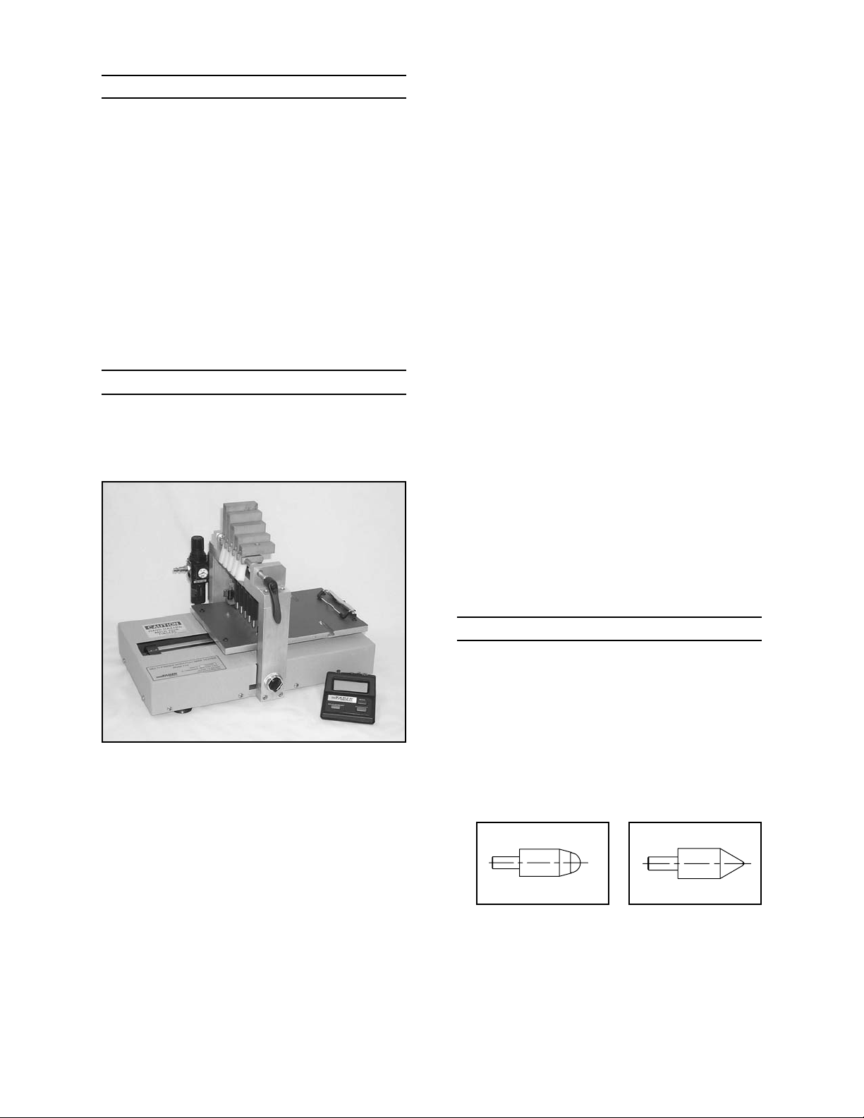
Interchangeable scratch tips include a precision
tungsten carbide ball mounted to the contact end.
The tips are 1.0mm diameter hemisphere for
scratch testing and 7.0mm diameter hemisphere
for mar testing. An optional holder permit s testing
with a conical diamond scratch tool.
The distance between the bottom of the gantry
and specimen table permits testing of flat specimens up to 22mm in thickness. Or, the 'free-floating' feature of the spline-shaft fingers enables you
to evaluate slightly contoured specimens provided
they are rigid or adequately supported. A springloaded specimen holder is standard and can be
mounted to the end or side of the moveable platform. For narrow and odd shaped parts,
adjustable hold-down clamps are available.
INSTRUMENT SET-UP
Remove all contents from the shipping container
and verify that you have all the components.
1. Set the instrument on a flat, level surface.
Four suction cup feet will secure the instrument to the surface.
2. Install the appropriate tips (scratch or mar)
into the end of each spline-shaft finger. Do
not over-tighten.
3. Insert the spline-shaft fingers into the guide
bearings, by matching the pattern on the shaft
and bearing. Each bearing has been preadjusted at the factory. If a shaft DOES NOT
slide easily through the bearings, see MAINTENANCE - Spline Shaft Finger Adjustment.
INTRODUCTION
The Taber®Multi-Finger Scratch /Mar Tester is
used to measure the relative resistance or susceptibility of a material surface to scratching,
marring, gouging, scraping and other similar
physical damage not classified as ordinary wear.
Useful in quality control, materials development
and product development, applications for this
instrument are diverse. They include plastics;
rigid organic materials; paints and coatings; soft
metals; linoleum, plus many others. The most
common usage has been in the automotive
industry, including smooth or grained plastics
used in ornamentation or trim.
PRODUCT DESCRIPTION
The design of the Multi-Finger Scratch / Mar
Tester is based on the five-finger (five-arm)
scratching device described in popular automotive test methods.
The instrument includes a pneumatically driven,
moveable platform to which the test sample is
mounted. The platform moves in a linear fashion
and is operated by a control knob, for one or multiple pass testing. An electronic timer displays
the rate of speed, which is controlled by reducing
or increasing air pressure.
A gantry supports five independent spline-shaft
fingers, which provide a constant, vertical load on
interchangeable scratch tips (1.0mm or 7.0mm
diameter hemisphere). Offering a stable platform
to ensure the rigidity for the scratch tips, the
gantry system includes a handle to raise and
lower the spline-shaft fingers. In addition, five
support rests are incorporated to allow one or
more fingers to be moved to an upright, rest posi-
2 710 Operating Instructions ver 1.1
Mar Tip Scratch Tip
Page 4
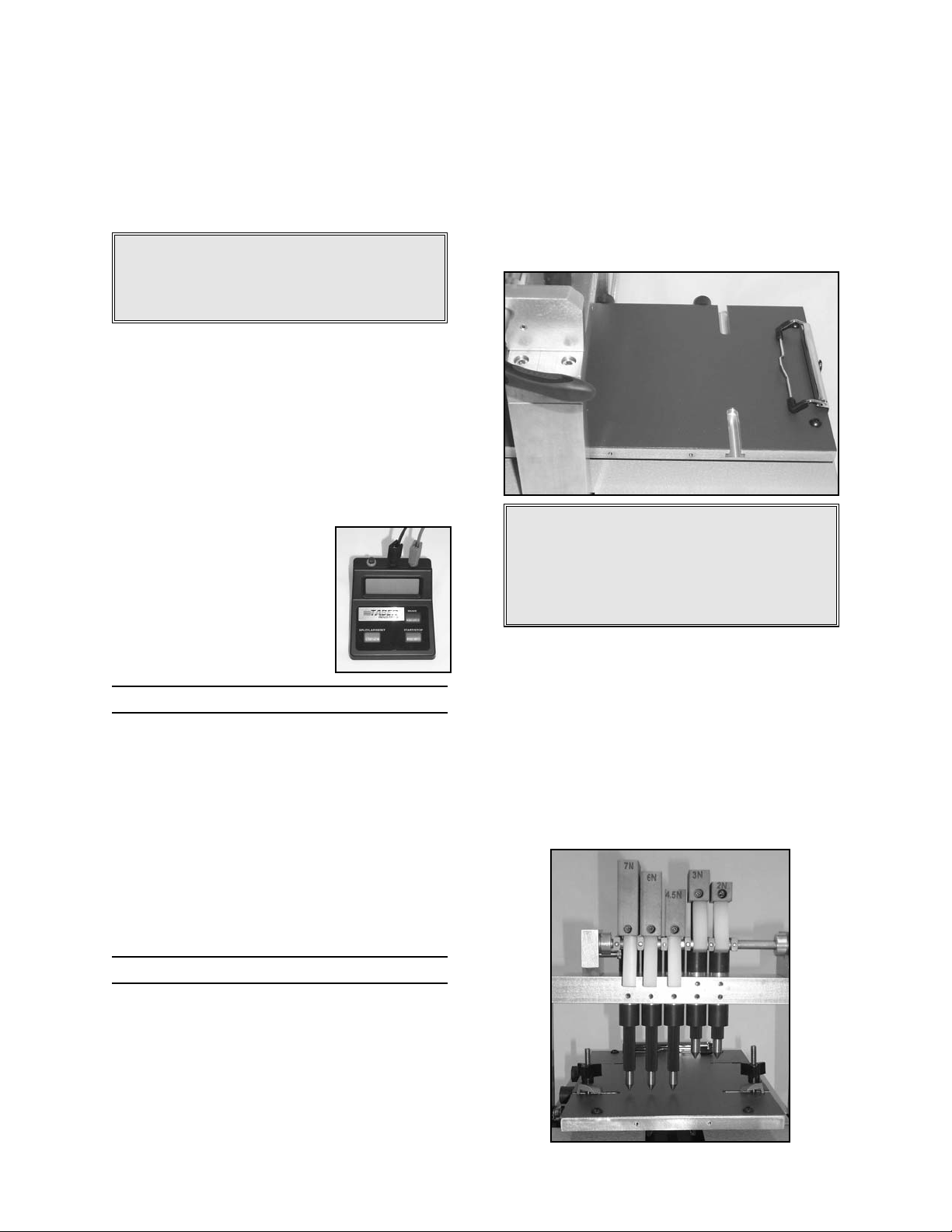
4. Select the weights to be used for testing, and
mount to the top of the spline-shaft finger.
Align so there is not any contact with the adjacent weight(s) and tighten in place using the
hex wrench. Weights should be mounted
from lowest to highest load, to permit ease of
evaluation.
X WARNING: To prevent damage to the
scratch tips, turn the handle to raise the
spline-shaft fingers after the weights are
assembled.
5. Attach the quick disconnect socket (sleevelock, with female ¼" NPT thread) to the air
supply hose, using Teflon tape to seal the
threads. If a local air supply is not available,
it is acceptable to use a compressor that provides 80 to 100 PSI pressure and has at least
a 2 gallon tank capacity. Fasten the hose to
the Multi-Finger Scratch / Mar Tester air
intake.
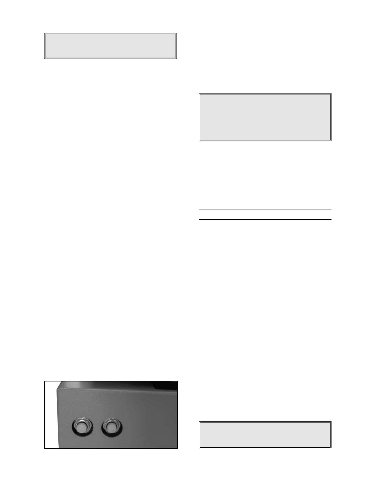
6. Connect the electronic
timer, matching the green
and black cables to their
respective sockets (the red
socket is not utilized). Insert
one AAbattery , ensuring the
correct polarity.
SPECIMEN SIZE
To provide for an accurate assessment, specimens should be flat panel or regions cut from a
sufficiently flat part. The recommended specimen size is 125mm x 300mm, with a thickness
no greater than 22mm. If taken from finished
parts, smaller or slightly contoured samples may
be used.
To test specimens that exceed the 22mm thickness, spacer blocks may be inserted into the
support arms of the gantry.
OPERATING PROCEDURES
Prior to testing, it is recommended that all samples be preconditioned in a controlled atmosphere (such as 23 ±2° C and 50 ±5% relative
humidity) for not less than 24 hours. Samples
should be tested under the same conditions.
Conducting a Test
• Using the handle, raise the 'fingers' to the
upright position.
• Place a sample on the platform so the surface
to be tested is facing upward and is located
under the spline-shaft fingers. Taking care
not to deform the specimen, secure it using
the spring clamp or other specimen clamps.
X WARNING: To prevent movement of the
specimen during testing, ensure the specimen
contacts a 'stop plate'. The spring clamp can
serve this purpose when mounted on the end
of the platform. The stop plate should be located on the opposite side of travel.
• If not already done, install the appropriate
scratch (mar) tips and weights.
• Using the red button reset the electronic timer.
• Lower the scratch (mar) tips onto the speci-
men surface and actuate the moveable platform by turning the control knob in the direction the table will travel. If one or more
scratch fingers are not required, a rest block
is provided to raise the finger out of position.
3 710 Operating Instructions ver 1.1
Page 5
SUGGESTION: For soft materials, it is recommended to test within 3 seconds after lowering the
scratch pins onto the specimen surface.
• Mark the direction of movement of the
scratching device on the panels, taking care
not to mark the surface just tested.
• To remove the specimen, raise the splineshaft fingers using the handle and release the
clamping.
• Evaluate the extent of the damage on the
sample.
Speed Adjustment
Prior to conducting any tests, you will need to
adjust the speed of the platform. A sliding velocity of approximately 100mm per second (± 10) is
normally recommended.
• Turn the knob on the air regulator/lubricator to
an air pressure between 80 - 100 psi. To
increase air pressure, turn the knob clockwise
(to decrease turn counterclockwise).
• Using the handle, raise the 'fingers' to the
upright position.
• Press the red button to reset the electronic timer.
• Actuate the moveable platform by turning the
control knob in the direction the table will travel. The number displayed on the timer, indicates the time in seconds it takes the platform
to travel 100mm.
• To adjust platform speed, turn the flow control
valves found on the right hand side of the
instrument. Turning the valve counter-clockwise will increase the speed, while turning it
clockwise will decrease the speed. If you are
testing in both directions, ensure the platform
travels at the same rate. The valve toward
the front of the instrument controls the speed
when the platform is moving to the left. The
valve toward the back, controls the speed
when the platform is moving to the right.
• After adjusting the flow control valve, lock in
place by tightening the lock thumbnut.
• Lower the scratch (mar) tips onto a ‘dummy’ test
specimen, and verify the speed adjustment.
To calculate the platform speed, divide 100mm
by the time shown on the display
X WARNING: It is possible for the speed of
the platform to exceed the capacity of the
automatic Start/Stop of the electronic timer.
Should this occur, disconnect the timer and
operate electronic timer by hand using the
Green button to Start and Stop.
Weight Adjustment
If you are not following a test method that indicates which weights are required, start with 3N,
5N, 7N, 10N, and 15N. Loads can be increased
or decreased accordingly.
CALCULATION OF RESULTS
Depending on the type of material under evaluation, the visual appearance of a scratch normally
involves changes in surface topography, color, or
brightness. Three methods are normally used:
Method A - Visual Evaluation:
Using a controlled light source, hold the sample
such that the scratch lines are in a horizontal position to the observer. The scratch line caused by
the highest weight should be at the upper position.
Rotate the sample, so the angle of observation
changes. The observer should be checking each
scratch line individually, and noting the point at
which the scratch lines emerge at the clearest visibility. Do not use the starting and ending point of
the scratch lines (approx. 10mm) in this evaluation.
Examine all scratch lines and rate according to a
Rating Scale 1 to 5 (1 = no scratch line at all; 5 =
severe scratch line). For plastic materials, indicate if the line exhibits signs of whitening.
Report the tip diameter, stylus loading level, and
Rating Number for each line on the surface of the
sample.
SUGGESTION:
A lightbooth with North Sky
Daylight (D65) has been recommend as a lighting
source for automotive specifications.
4 710 Operating Instructions ver 1.1
Page 6

Method B - Width/Depth:
Measure the width or depth of the scratch
(grooves) using an optical measuring device.
Method C - Image Analysis:
The scratch mark intensity may also be evaluated by using Image Analysis techniques.
NOTE: Detailed descriptions are recommended
when depicting scratch or mar damage. Items
that might be described include surface topography, material deformation, material removal, and
color changes. The following examples have
been used to describe damage in plastics:
- scratch is shallow (or deep)
- scratch is smooth, with a well defined shape
(or rough and deformed)
- scratch includes plastic flow of the material (or
cutting, tearing, cracking, chipping, crazing)
- scratch includes visible ripple marks at the
bottom (i.e. chevron or parabolic shaped)
- strain whitening is visible (or no change in
color)
INFLUENCES ON RESULTS
For comparable and reproducible tests, it is recommended the operations be performed under
conditions covered by an established test procedure. The following factors are known to affect
the scratch resistance of materials, and could
potentially impact your test results:
Test methodology
Test conditions (i.e. temperature or humidity)
Scratching speed
Geometry and condition of scratch tip or
indenter tool
Applied load
Material (i.e. filler type; additives; lubricant;
polymer type)
Surface roughness and grain direction
Type and thickness of surface treatment
Elastic properties of the specimen
Method of scratch assessment
Length of time between scratch and evaluation
Plastics
The properties of plastic materials can greatly
influence the evaluation of scratch and mar
resistance. It is important to be aware of the following factors and take them into consideration:
1. Many plastics have elastic recovery upon
removal of applied stress.
2. Many plastics have visco-elastic properties
and the stresses in the plastics may relax during loading.
3. Plastics may change structure during material
flow, which can also change the mechanical
properties of plastics.
Irregular Surfaces
The existence of 'chatter' in a scratch path may
indicate a non-uniform composition or the presence of surface irregularities. An irregular surface may also cause a scratch pin to 'bounce' on
the specimen surface, resulting in additional
impact force at landing points and additional
damage to the surface.
MAINTENANCE
Taber recommends annual factory calibration at
which time the unit will be thoroughly checked.
Care of the Scratch Tips
The precision cutting edge of the scratch (mar)
tips is fragile, and must be handled with care.
Depending on the material being tested, tips can
provide months of satisfactory service.
» Do not scrape the cutting edge of the scratch
tip against a hard surface, such as steel.
Doing so may prematurely dull the tool.
» The spline-shaft fingers must not be allowed
to drop against the specimen or platform.
Carefully lower them against the specimen
just prior to making a test.
The scratch tip will eventually become dull
through use. It is recommended that several
spare tips be kept on hand for replacement and
standardization purposes.
5 710 Operating Instructions ver 1.1
Page 7
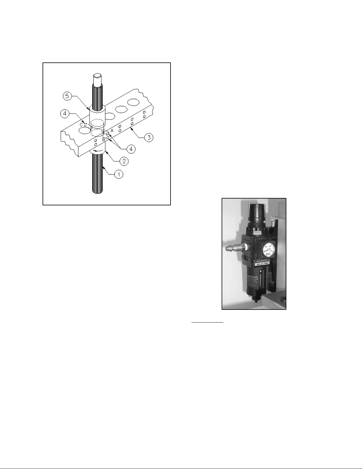
Spline Shaft Finger - Adjustment
The following procedure describes the correct
way to adjust the spline-shaft fingers.
1. Using hex wrench supplied, loosen set screw
and remove weight from spline-shaft finger.
2. If upper bearing (#5) is assembled tightly in
gantry and locked with bottom set screw (#4),
continue with step 3. Otherwise,
a. Remove spline shaft (#1) from bearing
assembly.
b. Hand-tighten upper bearing (#5) and
lock with bottom set screw (#4A).
c. Adjust lower bearing (#2) into beam until
shoulder of bearing is in contact with gantry .
d. Slide spline shaft (#1) into upper bearing
until shaft stops against lower bearing.
Lightly twist lower bearing clockwise until
spline grooves align into lower bearing
and slide freely.
3. Loosen two adjustment set screws (#4B & C)
approximately ½ to ¾ turn.
4. Apply light tension between spline shaft and
lower bearing by slightly twisting lower bearing counter-clockwise.
5. Using hex wrench, apply a light tightening force
to top set screw (#4B) locking lower bearing
into place. WARNING, DO NOT OVER
TIGHTEN SET SCREW. Spline shaft will no
longer move freely through bearings.
6. Tighten set screw (#4C) on the opposite side
of the gantry until spline shaft moves freely.
7. Re-attach weight and tighten set screws.
Load on Specimen Surface
To check the loading forces, measure directly
under the scratch (mar) tip, using a spring balance or equivalent. If necessary, adjust the
weight(s) to meet the required scratch force(s) on
the surface of the sample.
Lubricator / Regulator
The maximum inlet pressures and temperatures
are as follows:
150 psig (10.3 bar)
125° F (51.7° C)
Given normal operating conditions this unit will
be trouble-free. It is recommended that you service the unit at least every six months.
CLEANING:
To clean bowl assembly:
a. Depressurize unit.
b. Remove bowl and bowl guard assembly by
turning counterclockwise.
c. Inspect bowl daily for damaged or deteriorat-
ed seals. Replace with original manufacturers
approved seals and bowls.
d. If bowl becomes dirty, replace it or clean it by
wiping the bowl with a soft dry cloth or a mild
detergent.
e. Before returning to service, ensure that all
seals have been reinstalled or replaced.
6 710 Operating Instructions ver 1.1
Page 8

f. Reinstall bowl and bowl guard assembly and
rotate bowl guard clockwise to securely lock
in place. Align arrow on bowl guard with
arrow on lubricator body.
Occasionally, liquid water will get trapped in the
lubricator bowl. Since water is denser than oil,
the water will migrate to the bottom of the bowl.
Periodically clean bowl to remove the liquid
water.
ADDING OIL
: Use clean oil, preferably SAE 10 or
lighter. Do not use phosphate ester or diestor
based fluids in lubricators.
The lubricator can be filled under pressure by
removing the fill-plug slowly, allowing the pressure in the bowl to vent to atmosphere. After the
pressure is bled off, the fill plug may be removed
completely and oil poured into the fill port. When
the fill plug is removed, a small amount of air will
be venting from the fill port. This is to serve as
an audible signal denoting that the unit is in fact
under pressure. If faster filling is desired, slowly
remove the fill plug to vent the bowl pressure to
atmosphere. Then remove the bowl and bowl
guard assembly by turning counterclockwise. Fill
the bowl, reposition the bowl o-ring seal and reinstall the bowl into the body and turn clockwise to
securely lock in place. Reinstall the fill plug. The
unit is ready for use.
ADJUSTING DELIVER
Y RATE: The oil delivery
rate will change automatically to deliver more oil
during increase airflow demand and less oil for
airflow lower than the original setting. To adjust
and set oil delivery rate, the unit must be pressurized and flowing air. Turn the transparent sight
dome counter-clockwise to initiate/increase oil
delivery. Turn the sight dome clockwise to
decrease/stop oil delivery.
If the oil delivery rate should drop, the lubricator
should be inspected and cleaned to remove contaminates.
Electronic Timer
The electronic timer has been designed to offer
accurate time measurement over a long period
provided the following cautionary steps are maintained,
• It should not be used in environments, which
are very hot or humid.
• Do not use abrasive or corrosive substances
to clean.
• It should not be dropped or shaken vigorously.
FACTORY SERVICE
Should your Multi-Finger Scratch / Mar Tester
require repair or adjustment, carefully pack it in a
rugged container with plenty of cushioning material. After obtaining a return authorization number from the factory, the unit should be shipped,
transportation charges prepaid, to:
TABER Industries
455 Bryant Street
North Tonawanda, New York 14120
USA
7 710 Operating Instructions ver 1.1
Page 9
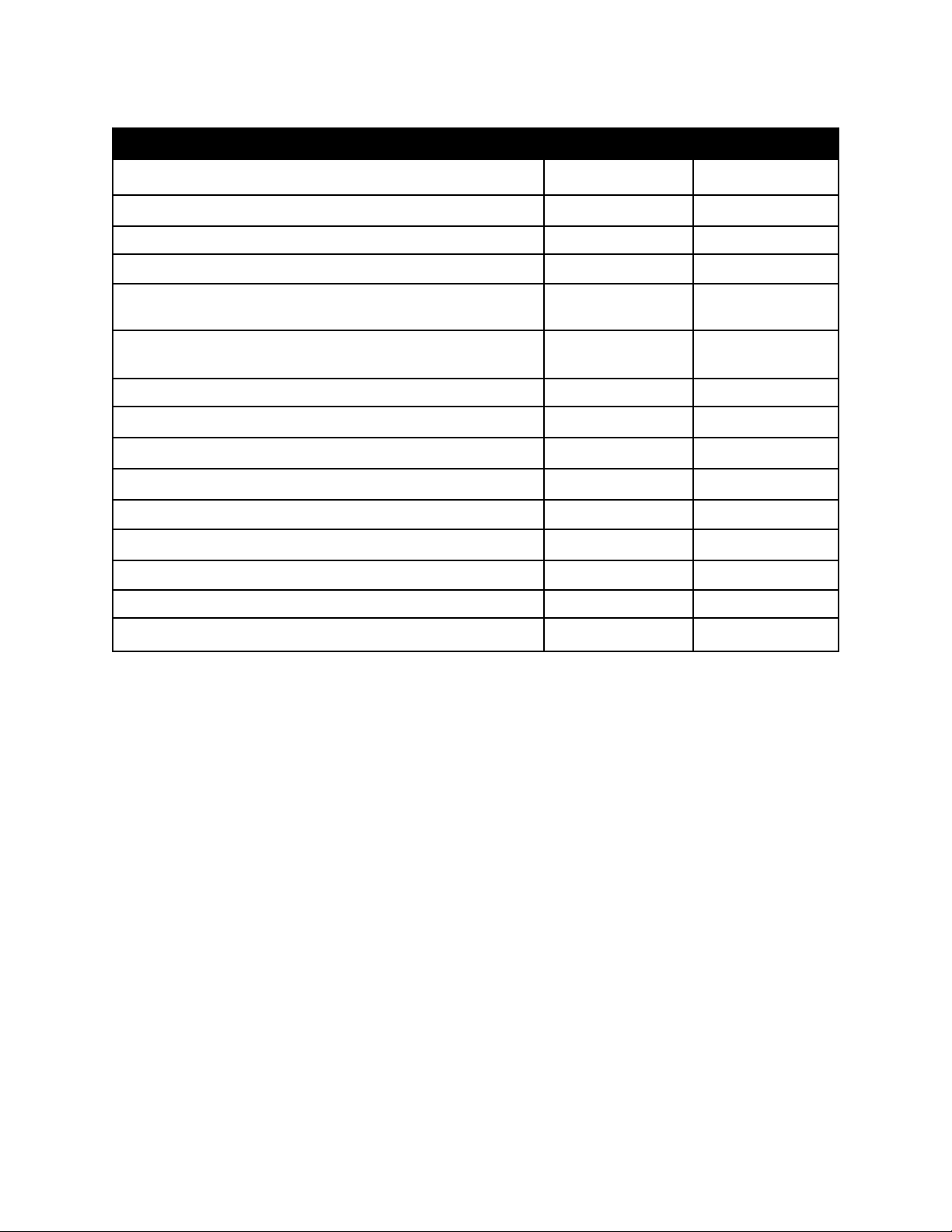
CONSUMABLES / ACCESSORIES
Description Model Number Part Number
Scratch Tip, 1.0 mm diameter hemisphere (each) 132347
Scratch Tip, 1.0 mm diameter hemisphere (set of 5) 132532
Mar Tip, 7.0 mm diameter hemisphere (each) 132348
Mar Tip, 7.0 mm diameter hemisphere (set of 5) 132533
Diamond Tool Holder, includes 121006 conical diamond tool
w/90° 3 mil (0.003”) radius point 132892
Diamond Tool Holder, includes 121006-1 conical diamond tool
w/90° 3.5 mil (0.0035”) radius point 132891
Conical Diamond Tool, with 90° 3 mil (0.003”) 139-55 121006
Conical Diamond Tool, with 90° 3.5 mil (0.0035”) 139-56 121006-1
Precision Weight Kit (Used to achieve 0.6N) 132740
Optional Weight Set (8N, 13N, 18N) 132401
Optional Weight (25N) 132352-5
Standard Specimen Hold-Down Clamp Kit (each) 132455
Oversized 'EZY' Specimen Hold-Down Clamp (each) 132399
Specimen Platform Protective Guard, Replacement 132451
3/32" Hex Wrench, Replacement 130808
TABER®Industries
455 Bryant Street
North Tonawanda, New York 14120
USA
Toll-Free: 800.333.5300
Phone: 716.694.4000
Fax: 716.694.1450
E-mail: [email protected]
WebSite: www.TaberIndustries.com
www.OrderTaber.com
8 710 Operating Instructions ver 1.1
Page 10

NOTES:
 Loading...