

Page 1

Taber® Rotary Platform
Abrasion Tester
Model 5135 / 5155
Operating Instructions
Page 2

TABLE OF CONTENTS
WARRANTY...............................................................2
CLAIMS FOR SHORTAGES......................................2
CLAIMS FOR DAMAGES ..........................................2
ICONS........................................................................2
CONTENTS ...............................................................2
INTRODUCTION........................................................3
PRODUCT DESCRIPTION........................................3
PRODUCT FEATURES .............................................3
INSTRUMENT SET-UP .............................................6
SETTING THE TEST PARAMETERS........................8
Setting the Speed 8
Setting the Reface Cycle Default 8
Setting the Counter Display 9
Setting the Test Cycles 9
Setting the Vacuum Level 10
Vacuum Only 10
Vacuum Nozzle Clearance 11
Accessory Receptacle 11
SPECIMEN SIZE .....................................................12
SPECIMEN MOUNTING OPTIONS.........................12
ADJUSTING FOR OPTIMAL PERFORMANCE.......19
Selecting Abradant 19
Mounting the Abrading Wheels 19
Wheel Loading (Auxiliary Weights) 20
Lowering the Abrading Heads 20
Adjusting the Height of the Vacuum Pickup Nozzle 21
Setting the Vacuum Level 21
Modified Vacuum Pick-up Nozzle 21
CHARACTERISTICS OF ABRADING WHEELS......22
Calibrase Wheels 22
Calibrade Wheels 23
Specialty Wheels / Abradants 23
REFACING ABRADING WHEELS...........................24
Refacing Resilient Wheels (Calibrase) 24
Refacing Vitrified Wheels (Calibrade) 26
SIGNIFICANCE AND USE.......................................28
TESTING PROCEDURES .......................................28
METHOD OF EVALUATION ....................................29
SPECIMEN PREPARATION....................................31
TEST PROCEDURES..............................................33
INFLUENCES ON RESULTS...................................40
MAINTENANCE .......................................................40
CALIBRATION / FACTORY SERVICE ....................43
OPTIONAL ACCESSORY INSTRUMENTS.............44
Sample Cutter 5000 44
Wheel Refacer 250 44
Quiet Cabinet 44
Grit Feeder Attachment 155 / 255 45
Multi-Media Abraser 5500 45
Scuffing Head Attachment 45
Haze Kit 46
Arm Height Extension Kit 46
Calibration Verification Kit 46
TEST METHOD REFERENCES ..............................47
CONSUMABLES / ACCESSORIES.........................48
Genuine Taber Wheel Sets (sold in pairs) 48
Wheel Refacing 49
Specimen Mounting 49
Test Accessories 50
Miscellaneous Accessories / Instruments 50
DATA SHEET...........................................................51
1 5135 / 5155 Operating Instructions ver 1.1
Page 3

WARRANTY
ICONS
Any product or part which, under normal
operating conditions in the facility of the original
purchaser, proves defective in material or
workmanship within one year from the date of
shipment by the company, as determined by an
inspection by Taber
®
Industries, will be repaired
or replaced free of charge provided you promptly
return the defective material. All claims must be
sent to Taber Industries with transportation
charges prepaid, notice of the defect and
verification the product has been properly
installed, maintained and operated within the
limits of rated and normal usage.
Replacement parts will be shipped FOB our
plant. The terms of this warranty do not in any
way extend to any product or part thereof that
has a life, under normal usage, inherently
shorter than the one-year indicated above. Said
warranty in respect of replacement of defective
parts and any such additional warranty or
representation expressly made, are in lieu of all
other warranties expressed or implied, including
any implied warranty of merchantability, or
fitness for any particular purpose.
Taber Industries reserves the right to make
changes without notice at any time in colors,
material, specifications, and models, and to
discontinue models.
CLAIMS FOR SHORTAGES
We use extreme care in selection, checking, and
packing to eliminate the possibility of error. If a
shipping error is discovered:
1. Carefully examine the packing materials and
ensure nothing was inadvertently overlooked
when the shipment was unpacked.
2. Notify the company you purchased the
product from and immediately report the
shortage. The materials are packed at the
factory, and should be complete if the box has
not been opened.
This instruction manual contains several notes
and warnings that should be observed carefully
by the user. The following icons denote these
notes and warnings:
Indicates a NOTE that warrants careful
attention. These notes may detail a step in
the procedure or point out a unique feature
of the instrument. Please read and follow
all notes carefully.
U Indicates a WARNING that warrants careful
attention. These warnings inform the user
of any dangers that may cause injury to the
operator and/or damage to the instrument.
It is imperative that you read and follow all
warnings carefully.
CONTENTS
Contents of the shipping container should
include the following:
• Auxiliary weights (500 gram load)
• Auxiliary weights (1000 gram load)
• E-100-125 Specimen Holder
• E-100-101 Clamp Ring for Specimen
Holder*
• Hex Wrench for Clamp Ring
• Genuine Taber Calibrase
• Genuine Taber Calbrade
• S-11 Abrasive Discs (100/pkg)
• S-36 Specimen Mounting Card (10 ea)
• S-12 Long-Handled Hand Brush
• Vacuum Unit with clean-up brush,
suction hose and stainless steel elbow
• Power Cords (115V and 230V)
• Operating Instructions
* Mounted on the Abraser
®
CS-10
®
H-18
Model
5135
1 set 2 sets
1 set 2 sets
1 2
1 2
1 1
1 pr. 2 pr.
1 pr. 2 pr.
1 pkg. 1 pkg.
1 pkg. 1 pkg.
1 1
1 1
1 1
1 1
Model
5155
3. Claims should be filed within 30 days from
shipment.
CLAIMS FOR DAMAGES
Claims for loss or damage in transit should be
made promptly and directly to the transportation
company.
2 5135 / 5155 Operating Instructions ver 1.1
Page 4

SECTION I
Understanding the Taber Abraser
INTRODUCTION
The Taber Rotary Platform Abraser Model 5135
and 5155 are durable, precision built test
instruments designed to evaluate the resistance
of surfaces to rubbing abrasion. Their field of
application is varied and includes tests of solid
materials, coated surfaces (paint, lacquer,
electroplated), plastics, textiles (ranging from
sheer silks to heavy upholstery), metals, leather,
rubber, linoleum, plus many others. In the
hands of a competent research technician, the
Abraser is capable of performing reproducible
tests, accurate within the variations of quality
inherent in the material itself.
axis of the sample. Figure 3 diagrams the
relative positions of the sample and abrading
wheels and the direction of their rotation.
One abrading wheel rubs the specimen outward
toward the periphery and the other, inward
toward the center. The resulting abrasion marks
(Figure 4) form a pattern of crossed arcs over
an area of approximately 30 cm
satisfactory for rating most materials.
2
(4.65 inch
2
),
PRODUCT DESCRIPTION
Characteristic rub-wear action of the Abraser is
produced by the contact of a test sample turning
on a vertical axis, against the sliding rotation of
two abrading wheels. The wheels are driven by
Figure 3
the sample in opposite directions about a
horizontal axis displaced tangentially from the
Figure 4
An exclusive and important feature of the 5135
and 5155 Abrasers is that the wheels traverse a
complete circle on the specimen surface,
revealing abrasion resistance at all angles
relative to the weave or grain of the material.
PRODUCT FEATURES
The Model 5135 and 5155 Abrasers have many
improved features compared to earlier versions
of the Taber Rotary Platform Abraser. These
are identified with an asterisk (*).
Operator Interface / Display*
The operator interface is an easy to use
membrane panel with tactile feel buttons and a
4-line digital display. Simple on-screen
instructions allow the operator to change the test
parameters and are accessed via the MENU
Page 5

button. The following test parameters are
shown on the screen: test mode, test duration,
test cycles (completed or remaining), turntable
speed, and vacuum suction level (%).
60 / 72 RPM Turntable Rotation Speed*
Models 5135 and 5155 offer both 60 rpm and 72
rpm turntable rotation speed. This enables the
operator to select the speed referenced in the
test standard.
NOTE: The turntable speed on previous versions of
the Taber Abraser was dependent on the electrical
line frequency. At 60Hz, the turntable speed was 72
rpm and at 50Hz the turntable speed was 60 rpm.
Preset Cycles Buttons*
The operator interface includes four commonly
used preset cycles buttons. This enables the
operator to automatically program 100, 500,
1000 or 2500 test cycles. The buttons may also
be used to “add to” the cycle count by the
corresponding incremental values.
Abrading Head Assemblies
Models 5135 and 5155 have independent
abrading arms of forged aluminum alloy that
pivot on ball bearings. The forward end of the
arm has a quick release wheel-mounting hub to
which the abrading wheel is mounted. The arms
are precision balanced to ensure exacting
results. Each arm applies 250 grams force
against the specimen with the wheel mounting
assembly in place (exclusive of the mass of the
wheels itself).
The outer end of the abrading head assembly
allows the auxiliary weight to be mounted
concentric with the abrading wheel. A stud on
the rear end of the abrading arm may be used to
carry a counterweight when it is desired to
reduce the wheel load to less than 250 grams
when testing delicate materials. It may also be
used to hold an abrading wheel as a
counterweight to compensate for the mass of
the working wheel.
Quick Release Mounting Hub*
An expanding collet hub design with push-button
operation permits quick wheel mounting, without
the need of a locking nut. A spring loaded,
beveled retaining nut provides a positive locking
force on the hub retaining lip making certain the
wheels remain securely fastened until
disengaged. The increased clearance results in
a larger viewing area of the test specimen.
4 5135 / 5155 Operating Instructions ver 1.1
Page 6

Auxiliary Weights
Model 5135 has two pairs of precision stainless
steel weights of 250 grams and 750 grams
furnished with the testing set. In addition to the
mass of the abrading arm itself (250 grams) they
provide standard wheel loads of 500 and 1000
grams. Figures 6 – 9 show abrasers with
different loads applied (per wheel).
Available counterweights reduce the 250 gram
load to 125 grams or 75 grams (Figure 9).
Counterweights may be used in conjunction with
the standard weights to further expand the range
of wheel loads. To offset the weight of the
working wheels, wheels may be placed on the
counterweight-mounting studs.
NOTE: For simplicity, each weight is marked with the
total load that will be exerted on the wheel.
Figure 9
Vacuum System
Models 5135 and 5155 include a vacuum unit
with a heavy-duty motor and life-lubricated
sealed bearings. With the vacuum power
connection plugged into the rear of the abraser
housing, the vacuum will be automatically turned
on when a test is commenced and shut off at the
end of the test cycles. A flexible rubber suction
hose connects it to the Abraser.
A vacuum pick-up nozzle is hinged to an
adjustable mount at the rear of the housing. The
height above the specimen is set by raising or
lowering the precision vacuum adjustment.
Figure 6
Figure 7
Precision Vacuum Nozzle Adjustment*
The height of the vacuum pickup nozzle is
adjusted by turning a knob. Each turn
represents 1.27 mm (0.05 inch) height adjustment,
making it significantly easier to set the proper
distance between the nozzle and specimen
surface. Located on the top of the instrument
next to the vacuum nozzle, the knob is easily
accessible.
Specimen Holder
The Model E100-125 specimen holder
accommodates most materials less than 6.35
(0.25 inch) thick with a 6.35 mm (0.25 inch)
mm
center hole. Rigid, flat specimens are secured
using the clamp plate and nut. For flexible
specimens, the E100-101 clamp ring is provided
in conjunction with the clamp plate and nut. An
S-19 rubber pad prevents specimens from
slipping during the test.
Specimen Holder Drive Shaft
The drive shaft for the specimen holder projects
vertically through the motor well in the Abraser
housing. Interchangeable specimen holders are
mounted to this shaft.
Figure 8
5 5135 / 5155 Operating Instructions ver 1.1
Page 7

Accessory Receptacles
The Model 5135 and 5155 Abraser permit
control of the vacuum unit and an accessory
instrument (wheel refacer or grit feeder) from the
main unit. The electrical receptacles are
integrated in the rear of the housing and marked
accordingly (Figure 10). The use of the
electrical receptacles is restricted to the
specified equipment.
Figure 10
NOTE: The power for the vacuum receptacle is
dependent on the voltage selector switch (115/230V).
The power for the accessory receptacle is 115V.
INSTRUMENT SET-UP
Installing Fuses and Setting the Voltage
1. Prior to operating the instrument, the
correct fuses must be inserted into the
fuse holder (found at the rear of the
instrument). See Figure 11.
115V, insert two (2) T10A, 5 x 20mm fuses
[Taber p/n 129735]
230V, insert two (2) T5A, 5 x 20mm fuses
[Taber p/n 128561]
NOTE: The factory default is set for 230V operation.
Aluminum Housing
The Abrasers are built with a rugged, compact
aluminum housing. This provides sufficient
weight and rigidity to ensure the instrument is
stable during testing. The overall dimensions of
the main units are:
Model 5135 27.9 cm x 40 cm x 25.4 cm
Model 5135 49.5 cm x 35.6 cm x 25.4 cm
(11” x 15.75” x 10”)
(19.5" x 14” x 10”)
Dual Voltage*
The 5135 and 5155 are dual voltage 115/230V,
60/50Hz switchable.
Abrading Wheels
The Taber Abraser is supplied with two types of
Genuine Taber abrading wheels, CS-10 and H-
18. For additional details on other available
wheels that may be used with this instrument,
see Characteristics of Abrading Wheels (page
21).
Auxiliary Port 1*
This feature is not currently used, but is being
supplied for future upgrades.
Figure 11
2. Slide the red voltage selector switch to the
appropriate voltage setting that the
instrument will be operated at.
NOTE: To remove the fuse holder, slide it out of the
switch selector. A small screwdriver may be used to
assist in the removal.
U WARNING: Prior to powering-up, ensure the
correct voltage is indicated per the detailed
instructions. Failure to set the correct voltage
configuration may result in damage to the Rotary
Platform Abrasion Tester’s electronic components
and will void any warranty.
* Denotes an improved feature
6 5135 / 5155 Operating Instructions ver 1.1
Page 8

General Set-Up
Figure 12
1. The Abraser unit should be placed on a
flat, level and rigid surface.
your convenience. Discard the power
cord not used.
5. Turn the instrument on. The ON / OFF
power switch is located on the back of the
instrument immediately above the cord.
The instrument is now ready to operate.
U WARNING: Failure to connect the Rotary
Platform Abrasion Tester to a surge protector or
surge suppressor may result in damage to the
instrument’s electronic components.
2. Position the vacuum unit in a ventilated
area near the Abraser. Remove the motor
housing and install the vacuum cartridge
filter and filter bag.
3. Insert the stainless steel vacuum hose
elbow into the vacuum hose receptacle
found in the rear of the Abraser housing.
Connect the flexible rubber suction hose
to the vacuum unit and the elbow.
U WARNING: DO NOT place the vacuum in a closed
cabinet without adequate ventilation. Failure to
provide sufficient airflow may cause the motor to
overheat. Resulting in damage to the vacuum.
Powering-Up
1. Plug the female connector of the Abraser
line cord into the rear of the instrument.
2. Attach the male connector of the vacuum
power cord into the receptacle marked
“VACUUM” at the rear of the Abraser.
When operating at 115V, a patch cord is
used to connect the vacuum unit to the
Abraser.
3. If any accessories are to be used (Grit
Feeder or Wheel Refacer), connect the
male connector to the receptacle marked
“ACCESSORY” at the rear of the Abraser.
4. Connect the instrument to a 115 or 230
volt, 60 or 50-cycle circuit. Two power
cords (115V and 230V) are provided for
7 5135 / 5155 Operating Instructions ver 1.1
Page 9

IMPORTANT
READ PRIOR TO USING INSTRUMENT
•
To activate the buttons on the membrane
switch, press firmly for approximately one (1)
second.
•
To access the MENU features or change the
MODE, the turntable must be stopped (the
Run or Reface Mode s atus indicated on the t
digital display must display “Stopped”).
1-Speed 4-Vacuum
2-Refacing 5-Outlet
3-Display 6-Reset
>Select Menu Option
1-Speed 4-Vacuum
2-Refacing 5-Outlet
3-Display 6-Reset
>0 Zero key for more
Alternating
Display
Screens
SETTING THE TEST PARAMETERS
Model 5155 Dual Abraser – The numerical
keypad is common to the entire instrument. The
digital display shows test cycles specific to each
turntable, and common functions to the entire
instrument (turntable speed and vacuum suction
level).
To change between the left or right turntables,
press either the START or STOP buttons on the
appropriate table. The last key depressed will
determine the side to which the data will be
entered, and is indicated by the word “KEYPAD”
displayed on the lower corners of the digital
display. For example, if the STOP key has been
depressed on the left side, any information
entered into the keypad will be for the left table.
Should the START or STOP key on the right
side be depressed, any values that are entered
will be for the right turntable.
Setting the Speed
Current Speed = *
*1- 60 Cycles/Minute
2- 72 Cycles/Minute
>Press 1 or 2
Current Speed = *
*1- 60 Cycles/Minute
2- 72 Cycles/Minute
>CLEAR key to return
Alternating
Display
Screens
Speed set to
72 Cycles/Minute
The speed of the Rotary Platform Abrasion
Tester is reported as CYCLES / MINUTE, where
one cycle is defined as a full rotation of the
turntable.
NOTE: The factory default speed is set at 60 RPM.
The speed of the Rotary Platform Abrasion
Tester can be selected as 60 or 72 rpm. The
tester will store the speed that was last selected
in memory and use this as a default until it is
changed. Speed is shown on the display.
The following instructions show how to change
the speed. To change speed, the instrument
must not be in operation (the Run or Reface
Mode status indicated on the digital display must
display “Stopped”).
1. Press the MENU button to display menu
options (see below for screen displays).
2. From the menu options, press 1 to select
the option to change speed.
3. Using the numeric keypad, enter “1” to
change to 60 cycles per minute or “2” to
enter 72 cycles per minute. The asterisk
(*) indicates the current speed selection.
4. Press START to begin testing.
8 5135 / 5155 Operating Instructions ver 1.1
NOTE: After pressing “1” or “2” in step 3, the display
screen will flash “Test speed set to ‘X’ Cycles/Minute”
to confirm your selection and will automatically return
to the main display screen.
NOTE: The turntables for the Model 5155 Dual
Abraser will rotate at the same rpm.
Setting the Reface Cycle Default
The Reface Mode allows you to reface the
wheels without adding test cycles to the
completed (remaining) test cycle count. This
convenient feature is ideal for any test that
requires the abrading wheels to be refaced at
intervals during the test.
The instrument is programmed with a default of
25 cycles. To change this value, follow the
instructions below.
1. Press the MENU button to display Menu
Options (see below for screen displays).
Page 10

2. From the menu options, press 2 to select
Refacing.
3. Enter a new value, and press ENTER to
save.
3. Using the numeric keypad, enter “1” to
display Completed Cycles or “2” for
Remaining Cycles. The asterisk (*)
indicates the current counter display.
1-Speed 4-Vacuum
2-Refacing 5-Outlet
3-Display 6-Reset
>Select Menu Option
Change refacing
default cycles: 25
>Enter new total
>CLEAR key to return
Change refacing
default cycles: 50
>Enter new total
>ENTER key to save
Change refacing
default cycles: 50
>Enter new total
>CLEAR key to cancel
Alternating
Display
Screens
Default number of
Reface Cycles
set to
50 cycles
NOTE: After entering the new value in step 3 and
pressing ENTER, the display screen will flash “Default
number of Reface Cycles set to X cycles” to confirm
your selection and will automatically return to the main
display screen.
NOTE: If a new value is entered with the numeric
keypad or a Preset Cycles button when the Abraser is
in the Reface Mode, the number of reface cycles will
change. However, this DOES NOT change the default
refacing cycle value.
U WARNING: Do not exceed 50 cycles on an S-11
refacing disc. If more than 50 cycles are required,
replace the refacing disc.
Setting the Counter Display
The Rotary Platform Abrasion tester can be
programmed to show “Completed Cycles” (count
up) or “Remaining Cycles” (count down). The
following explains how to change the display:
1. Press the MENU button to display Menu
Options (see below for screen displays).
2. From the menu options, press 3 to select
Display.
1-Speed 4-Vacuum
2-Refacing 5-Outlet
3-Display 6-Reset
>Select Menu Option
Current Count Mode=*
*1- Completed Cycles
2- Remaining Cycles
>Press 1 or 2
Change Count Mode=*
*1- Completed Cycles
2- Remaining Cycles
>CLEAR key to return
Alternating
Display
Screens
Counting mode set
to display
Remaining Cycles
NOTE: After entering the new value in step 3, the
display screen will flash “Counting mode set to display
Remaining (Completed) Cycles” to confirm your
selection and will automatically return to the main
display screen.
Setting the Test Cycles
The Abraser can be preset to any number of test
cycles below the maximum value of 50,000.
The total cycle count shown on the display
screen defaults to the test duration value that
was last entered.
To reset the test cycles, depress the CLEAR
key, and then select the desired number of test
cycles using one of the two options discussed
below. The Abraser turntable will stop
automatically at the selected number of test
cycles. To begin testing a new specimen, press
the CLEAR key. It is not necessary to re-enter
the same value of test cycles at the beginning of
each test.
Option 1
new value may be entered with the numeric
keypad. After the desired number of test
cycles has been entered, press the ENTER or
START key. If an incorrect value is entered,
press the CLEAR key to return to the original
value.
Option 2
you conveniently enter values of 100, 500,
: With the Abraser in Run Mode, a
: The PRESET CYCLES buttons let
9 5135 / 5155 Operating Instructions ver 1.1
Page 11

1000 or 2500. Press the 0 button to reset the
cycle count, and then select a preset cycle
button(s) to set the new test cycle. A
PRESET CYCLES button may be pressed
during operation or when a test is stopped, to
increase total cycles by that amount.
It is possible to increase (or decrease) test
duration beyond the original cycles. To override,
the number of turntable revolutions must be a
value greater than the completed cycles. Press
ENTER to accept the new value.
For the model 5155 Abraser, both turntables can
be preset to different values depending on the
nature of the test. Prior to entering a new value
for the test cycles, ensure the KEYPAD indicator
is shown on the correct turntable. To change
between the left or right turntables, press either
the START or STOP buttons on the appropriate
table. The ongoing cycle count for each
turntable will be displayed in the corresponding
digital readout.
NOTE: An abrasion cycle, or test cycles, is defined
as one complete revolution of the specimen in contact
with the abrading wheels.
NOTE: The instrument can be stopped at any time for
inspection and started up again (by depressing the
START key) without interrupting the counter reading in
the digital display.
NOTE: Entering a new value DOES NOT
automatically zero the completed cycle count. This
enables you to reprogram the total test cycles to
continue testing beyond the original number of cycles.
If you change total cycles to a value less than the
completed cycles, you must first press CLEAR to zero
the completed cycle count, enter the new value and
then press START.
Setting the Vacuum Level
The vacuum furnished with the Model 5135 and
5155 Abrasion Test Sets is equipped with a
variable vacuum control. For test control and
standardization of vacuum suction, the vacuum
level is calibrated to values of 50 – 100%.
Changing the vacuum level adjusts the speed of
the vacuum unit motor and the corresponding
vacuum suction for accurate standardization and
control of test procedures.
The vacuum level should be set high enough to
lift the abraded particles, but not lift flexible
samples. A vacuum level of 100% is
programmed into the Abraser. If you require
less than 100% vacuum, follow the instructions
below. The vacuum level will default to the
value that was last entered.
1. Press the MENU button to display Menu
Options (see below for screen displays).
2. From the menu options, press 4 to select
Vacuum.
3. Enter a new value between 50 and 100,
and press ENTER to save.
1-Speed 4-Vacuum
2-Refacing 5-Outlet
3-Display 6-Reset
>Select Menu Option
Change Vacuum Level
>Enter new level
>CLEAR key to return
Change Vacuum Level
>Enter new level
>ENTER key to save
Change Vacuum Level
>Enter new level
>CLEAR key to return
100%
90%
Alternating
Display
Screens
90%
Vacuum Level set to:
90%
NOTE: The factory default vacuum level is set at 100.
U WARNING: Do not use the vacuum pickup for
tests on wet materials. When conducting wet
tests, raise the vacuum nozzle, and disconnect the
electrical cord to the vacuum unit.
U WARNING: Do not place the v acuum in a closed
cabinet without adequate ventilation. Failure to
provide sufficient airflow may cause the motor to
overheat, resulting in damage to the vacuum.
Vacuum Only
The VACUUM ONLY key allows you to operate
the vacuum unit without the Abraser. This may
be necessary to clean the drive shaft and
specimen holder cavity or to properly operate
the Wheel Refacer.
If only the vacuum is needed, turn the Abraser
on then depress the VACUUM ONLY key. The
vacuum will operate at the vacuum level last
entered.
10 5135 / 5155 Operating Instructions ver 1.1
Page 12

Vacuum Nozzle Clearance
The height of the vacuum pick-up nozzle is
adjustable and may be raised or lowered using
the knob found by the right abraser arm (Figure
13). Each full rotation of the adjustment knob
raises or lowers the nozzle by 1.27 mm
inch)
. To assist with vacuum nozzle adjustments,
a calibrated shim may be placed between the
test specimen and the nozzle.
(0.05
the start of the Grit Feeder at the same time a
test is commenced.
1. Press the MENU button to display Menu
Options (see below for screen displays).
2. From the menu options, press 5 to select
Outlet.
3. Using the numeric keypad, enter “1” for
Continuous Power or “2” for Power While
Testing. The asterisk (*) indicates the
current mode.
Figure 13
Many established test methods define the gap
between the test sample and vacuum pick-up
nozzle. For most flexible materials, the vacuum
nozzle should be no closer than 6.35 mm
. For rigid materials, the vacuum nozzle is
inch)
normally specified as a 1.59 mm
3.18 mm
The amount of vacuum suction is influenced by
the type of material being tested and height of
the nozzle above the specimen surface. The
intent of the vacuum system is to remove the
abraded particles BUT NOT LIFT THE TEST
SPECIMEN.
(0.125 inch) gap.
(0.0625 inch) to
(0.25
U WARNING: When testing flexible materials,
ensure the suction from the vacuum nozzle does
not lift the specimen. Any contact between the
specimen and vacuum pick-up nozzle during the
test, will cause additional wear that may influence
the test results.
1-Speed 4-Vacuum
2-Refacing 5-Outlet
3-Display 6-Reset
>Select Menu Option
Current Mode=*
*1- Continuous Power
2- Power While Test
>Press 1 or 2
Current Mode=*
*1- Continuous Power
2- Power While Test
>CLEAR key to return
Aux. Outlet Mode
Power While Testing
Set To:
U
WARNING: The use of the electrical receptacles
is restricted to the specified equipment only.
Alternating
Display
Screens
Accessory Receptacle
Incorporated into the Model 5135 and 5155
Abraser is an accessory receptacle to supply
power to either the Wheel Refacer or Grit
Feeder Attachment.
Through the MENU, you can choose to have
continuous power supplied to the receptacle or
ONLY while you test. When operating the
Wheel Refacer, select continuous power. This
allows you to reface wheels at any time,
provided the instrument is turned on. However
when operating the Grit Feeder, voltage should
be supplied ONLY when a test is being
conducted. This will enable you to coordinate
11 5135 / 5155 Operating Instructions ver 1.1
Page 13

SPECIMEN SIZE
The width of the wear path is 12.7 mm (0.5 inch),
and located 31.75 mm
of the specimen. The size of the specimen may
vary depending on the material being evaluated.
For most rigid materials, a sample approximately
100 mm
(4.0 inch) square is recommended.
Flexible specimens are typically circular and
require the use of the clamp ring. If a mounting
card is used, the specimen should be
approximately 108 mm
no mounting card is used, a 135 mm
specimen is required such that the clamp ring
will grip the overlapped material.
If the specimen is less than the suggested size,
it is possible to position two or more specimens
on a mounting card to meet the size
requirement. If the edges are not flush together
or if the samples are of different thickness, the
edges may wear at a different rate than the rest
of the specimen.
The standard material thickness that can be
evaluated with the Taber Rotary Platform
Abraser is 6.35 mm
greater than 6.35 mm (0.25 inch) but less than
12.7 mm
(0.5 inch), the S-21 extension nut may
be used. Specimens with a thickness greater
than 12.7 mm
(0.5 inch) can be tested using the
arm height extension kit.
(1.25 inch) from the center
(4.25 inch) in diameter. If
(5.25 inch)
(0.25 inch). For materials
Figure 14
Mounting Sheets (S-37 and S-37-1)
These 108 mm (4.25 inch) sheets are coated on
both sides with pressure sensitive adhesive
overlaid with protective paper that is peeled off
just prior to use. Thinner than the S-36 and S36-1, mounting sheets are used to provide a
non-slip attachment of the specimen to the
surface of the turntable and are especially useful
for materials difficult to drill a center hole (such
as glass or ceramics). Mounting sheets are
available as square (S-37) or round (S-37-1),
and have a test record printed on both sides
enabling them to be used as a mounting card.
SPECIMEN MOUNTING OPTIONS
To expand the versatility of the Taber Abraser,
mounting options and interchangeable specimen
tables are available to evaluate materials not
easily tested with the standard configuration. All
tables are engineered with a ball plunger and
drive pin spring clutch that locks the table onto
the motor shaft. This prevents the table from
shifting during a test, but allows for it to be easily
removed for specimen inspection or to clean the
motor shaft cavity. To gain access to the
specimen holder, lift the suction nozzle on its
hinge and raise the abrading arms up and back
beyond their balance point.
Mounting Cards (S-36 and S-36-1)
These 108 mm (4.25 inch) rigid cards are coated
on one side with pressure sensitive adhesive.
Designed to hold textile and other flexible test
specimens tightly to the mounting surface, they
prevent wrinkling while undergoing testing. A
test record form is printed on the backside of the
card for permanent record. Mounting cards are
available as square (S-36) or round (S-36-1).
Figure 15
Figure 16
12 5135 / 5155 Operating Instructions ver 1.1
Page 14

Specimen Holder (E100-125)
The specimen table equipped with the Abraser
(E100-125) has been designed to accommodate
most materials less than 6.35 mm
thick. Unless optional accessories are utilized, a
6.35 mm (0.25 inch) center hole must be punched
or drilled in the specimen so it can be securely
fastened to the threaded center post.
To secure rigid materials, use the clamp plate
and nut. For flexible materials, also use the
supplied E100-101 specimen clamp ring. A 108
mm
(4.25 inch) diameter rubber pad (S-19) is
provided to ensure a non-slip surface.
(0.25 inch)
Specimen Holder with Ring Clamp
(E140-14)
Rigid specimens that are slightly warped and
less than 6.35 mm
either dry or wet tested using the E140-14 Ring
Clamp Holder. Eight (8) screws are spaced
evenly on the clamp plate, and when tightened,
will correct for slightly warped conditions. This
holder can be furnished with (E140-14-S) or
without (E-140-14-NS) a center clamping screw.
Specimens should be 137 mm
diameter with a 6.35 mm
(0.25 inch) in thickness can be
(5.375 inch) in
(0.25 inch) center hole.
Figure 21
Figure 19
13 5135 / 5155 Operating Instructions ver 1.1
Figure 22
Page 15

Textile Specimen Holder – Tensioning
Type (E140-15)
Textile Holder – Tensioning Type for Wet
or Dry Testing (E140-18)
Similar to the standard specimen holder, the
E140-15 Tensioning Textile Specimen Holder
has a slightly raised wear track. This gives
textile and other flexible specimens additional
tension when the clamp ring is drawn down over
the edge of the holder and the clamp plate is
tightened in the center recess. Requires a 134
mm (5.25 inch) diameter specimen with a 6.35 mm
(0.25 inch) center hole. This holder is not
recommended for use with rigid specimens or
with mounting cards.
NOTE: For proper mounting, place the specimen on
the holder and draw it taut with the clamp ring.
Tighten the ring, and then mount the clamp plate.
The E140-18 holder is designed to give an initial
stretch to woven fabrics so that they may be
tested while moist with minimum tendency to
wrinkle. A raised wear track provides additional
tension on the specimen, while a 9.53 mm
inch)
rim helps retain any liquid. Requires a
159mm
inch)
(6.25 inch) specimen with a 6.35 mm (0.25
center hole.
(0.375
NOTE: For proper mounting, place the specimen on
the holder, position the clamp ring and mark the holes.
Where each hole was marked, make a small cut such
that the screws may be aligned and mounted to the
holder. Partially tighten down the clamp ring. Draw
the fabric taut under the ring, tighten the screws, and
trim off excess material around the edge. Tighten the
clamp plate.
NOTE: When the fabric specimen is to be tested at
specific moisture content it must be conditioned to that
content before it is mounted on the holder.
Figure 24
Figure 27
Figure 25
14 5135 / 5155 Operating Instructions ver 1.1
Figure 28
Page 16

Drive Pin Type Holder (E140-19)
Threaded Ring Specimen Holder (E140-21)
The E140-19 Drive Pin Holder is intended for
rigid, square specimens that do not have a
center-mounting hole. The specimen is adhered
to the holder with S-37 or S-37-1 mounting
sheets and opposing driving pins prevent it from
slipping while the test is being conducted.
NOTE: An example where this holder may be useful
is for glass or ceramic tile, which may be difficult to
drill a center hole.
The E140-21 Threaded Ring Specimen Holder
incorporates a clamp plate and flanged clamp
ring to test slightly warped, rigid specimens.
The ring is threaded to the body of the holder,
which securely clamps the outer edges of
specimens up to 137 mm
(5.375 inch) diameter.
Figure 30
Figure 31
Figure 33
Figure 34
15 5135 / 5155 Operating Instructions ver 1.1
Page 17
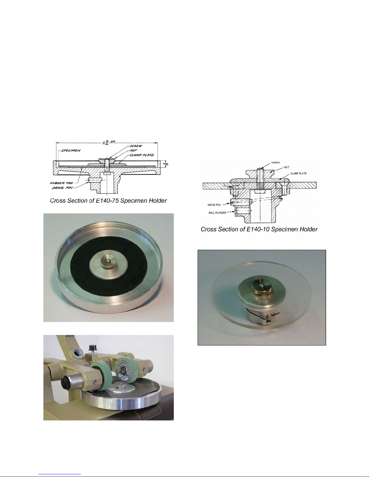
Rimmed Specimen Holder (E140-75)
The E140-75 Rimmed Specimen Holder has a
9.53 mm
liquids during a test. A rubber pad is adhered to
the table to prevent specimens from slipping
during the test. This holder is used for wet
testing materials to determine the effect of
absorbed and / or surface moisture on abrasion
resistance. To prevent splash over on the
instrument, use only a sufficient amount of liquid
to cover the specimen. Specimens may be up
to 140mm
(0.375 inch) raised rim for retaining
(5.5 inch) diameter.
Specimen Holder with Transparent Base
(E100-10)
This Transparent Base Holder (E100-10) is
manufactured with a transparent base and
recommended to be used with the E100-102
clamp ring. When evaluating textile specimens,
the table may be removed from the Abraser to
view the abraded specimen against a strong
light source to determine the worn condition of
the threads. This eliminates the need to remove
the specimen from the holder permitting the test
to be continued if desired.
NOTE: The vacuum is not used when conducting wet
tests.
NOTE: This holder has also been used with a small,
high intensity light bulb located beneath the specimen
holder which activates a photocell and electronic relay
through the test material that turns off the Abraser
when the established wear point is reached.
Figure 36
Figure 37
16 5135 / 5155 Operating Instructions ver 1.1
Figure 39
Page 18
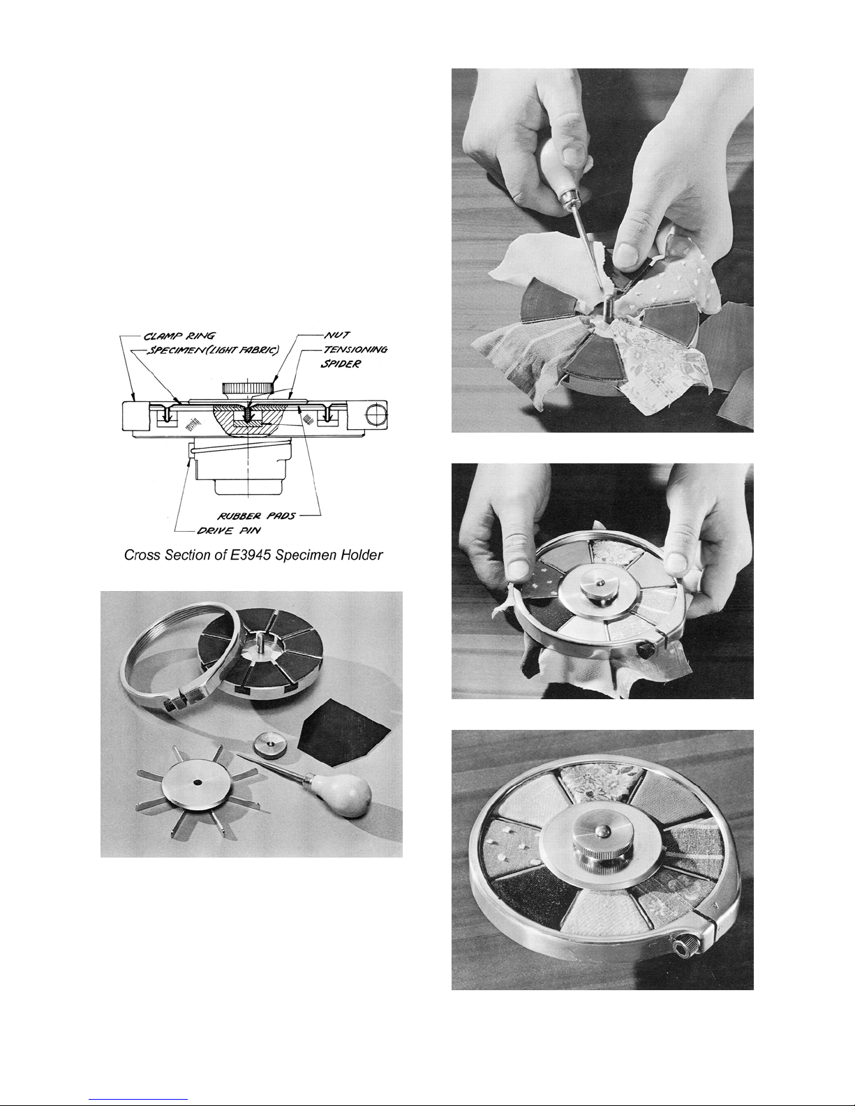
Multiple Specimen Holder (E3945)
Divided into sections, the E3945 Multiple
Specimen Holder permits eight samples to be
tested simultaneously for quick comparisons.
Intended for nylon hosiery and lightweight
fabrics, the normal test load used with this table
is 125 or 250 grams. A template is provided as
a guide to cut specimens to the proper size.
NOTE: To mount samples, place each over its
mounting area with the narrow end toward the center.
Using the insertion tool, tuck the edges into the slots.
Fit the arms of the spider clamp plate into the slots
and smooth out any wrinkles. Mount the clamp plate
and tighten. Finally, draw all samples taut with the
clamp ring and tighten.
Figure 42
Figure 41
Figure 43
17 5135 / 5155 Operating Instructions ver 1.1
Figure 44
Page 19
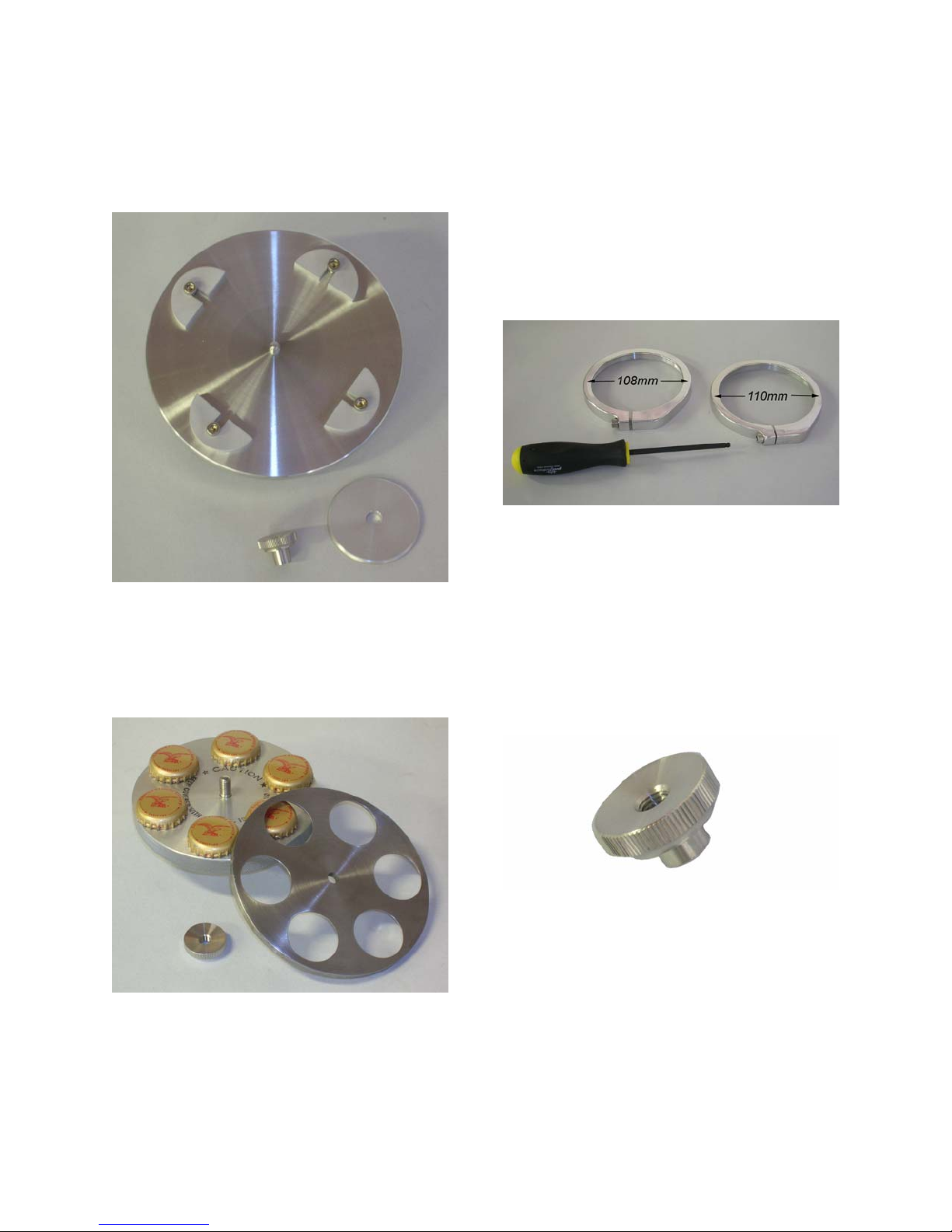
Sliding Mount Specimen Holder
This holder is designed to test small, rigid
materials. With two adjustable slide mounts,
four 50 mm
mounted to this table. To accommodate the
threaded center post, one corner of each
specimen must be trimmed.
(2.0 inch) square samples can be
prevent crushing of the specimen fibers near the
wear path.
Specimen Clamp Ring
Two specimen clamp rings are available for the
Taber Rotary Platform Abraser. The standard
clamp ring provided with the instrument is Model
E100-101. This has a 108 mm
and is designed for flexible materials up to 0.79
mm (0.0312 inch) thick. With a 110 mm (4.328 inch)
I.D., model E100-102 will accommodate flexible
materials up to 1.59 mm
(0.0625 inch) thick. E100-
102 is also referenced as clamp ring “B”.
Figure 47
(4.265 inch) I.D.
Figure 45
Specialty Tables
If your product cannot be evaluated with one of
our standard specimen tables, please contact
Taber Industries directly.
Figure 46
Extension Nut (S-21)
To secure specimens that are 6.35 mm (0.25 inch)
to 12.7 mm
(0.5 inch) in thickness, the S-21
extension nut should be used. A 9.525 mm
(0.375 inch) center hole must be drilled into the
specimen to accommodate the longer shoulder.
NOTE: For specimens that exceed 12.7 mm (0.5
inch) thickness, use the Arm Height Extension Kit (see
Accessory Instruments).
Figure 48
Specimen Clamp Plate
When using the Scuffing Attachment to test
carpeting and other floor covering materials, a
smaller diameter clamp plate 31.75 mm
is available. The smaller diameter helps to
18 5135 / 5155 Operating Instructions ver 1.1
(1.25 inch)
Page 20
ADJUSTING FOR OPTIMAL
PERFORMANCE
Selecting Abradant
Wear is a complex phenomenon and trying to
replicate it exactly in a laboratory setting can be
a challenge. There are numerous factors that
influence real-life wear, and identifying each
influence can be unwieldy. The ideal solution
would be to analyze the product in actual use,
however this could take months or years before
useful data becomes available. In addition, this
type of testing is often uncontrolled and costs
tend to be prohibitive.
Accelerated testing with the Taber Abraser is a
cost effective solution that provides a predictive
performance under a specified set of criteria.
While laboratory tests may not be 100%
representative of actual wear, established test
methods typically eliminate extraneous
variables, thereby enabling materials to be
evaluated using the same set of criteria.
The choice of which abrasive wheel to use with
your instrument is highly dependent on the
material that is being evaluated. Ideally, test
results should be correlated with field
observations. Many test methods specify which
genuine Taber abrasive wheel should be used.
If you are not following an established test
method, trial and error is suggested to help
determine whether one abrasive wheel is better
than another. Genuine Taber CS-10 and H-18
wheels are provided to assist with this
evaluation. It is often the case that materials
degrade faster with the more demanding
conditions of accelerated testing however as a
basic rule of thumb, a minimum number of test
cycles should be completed before the end point
occurs (i.e. 300 cycles). Otherwise, the
abradant may be too aggressive or the load is
too great.
beveled retaining nut provides a positive locking
force making certain the wheels remain securely
fastened. This eliminates the possibility of a
locking nut becoming loose during testing.
Figure 49
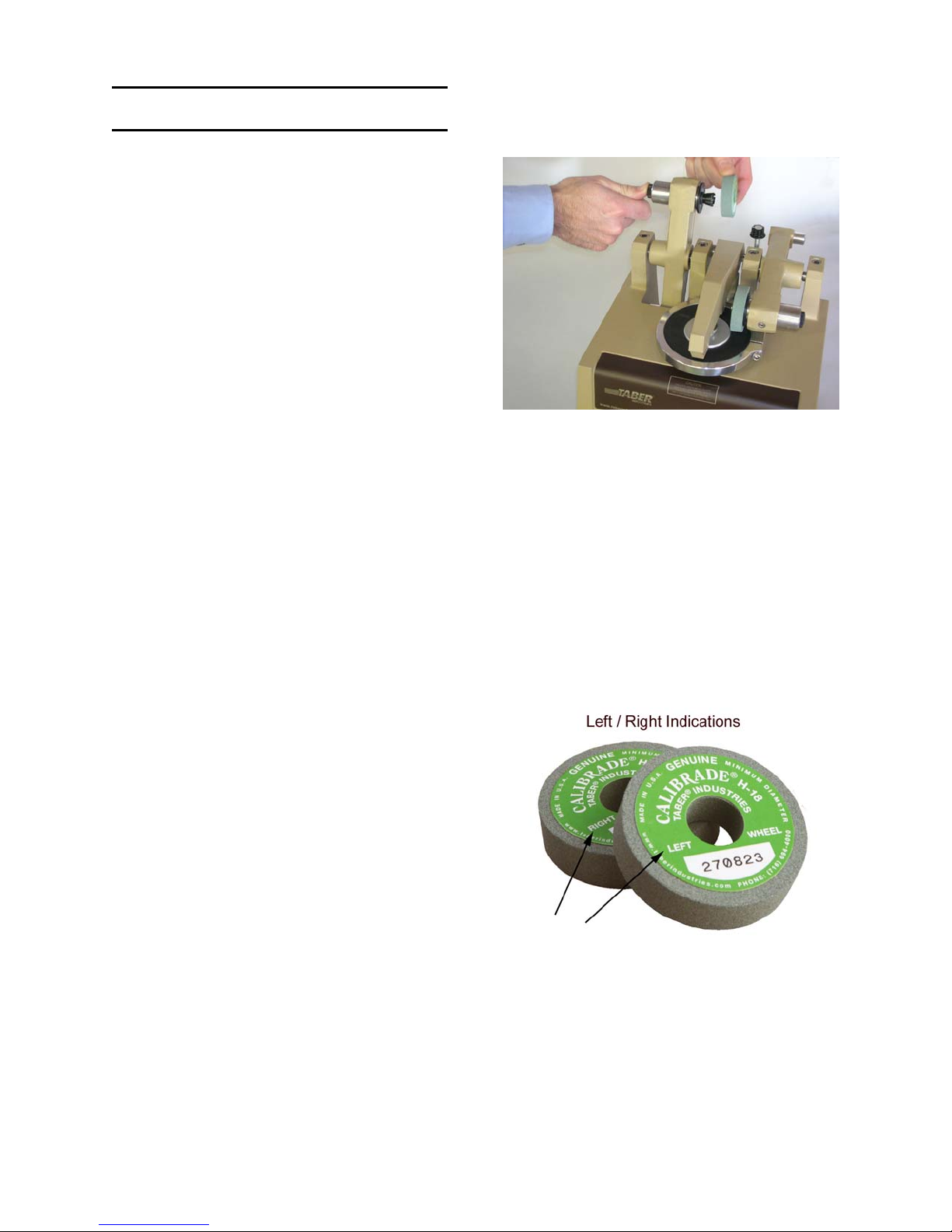
Genuine Taber abrading wheels are supplied in
pairs. A close inspection of the wheel labels will
show that one is marked “Left Hand”, while the
other is “Right Hand” (Figure 50). The purpose
of this is to assure that the mounting position of
the wheels will be duplicated when they have
been removed after use and later reinstalled.
The wheel labels should be facing inward.
Before preparing the wheels for testing, check
their condition and expiration date (if applicable).
Wheels that appear ‘out-of-round’ must be
refaced with the Wheel Refacer. Refer to
Refacing Calibrade Wheels on page 24.
Genuine Taber abrasive wheels are available in
a variety of standardized formulations. Each
offers unique features and provides a means to
precisely and effectively evaluate your material.
For additional information, see Characteristics of
Abrading Wheels on page 21.
NOTE: To inquire about custom formulations, please
contact Taber Industries.
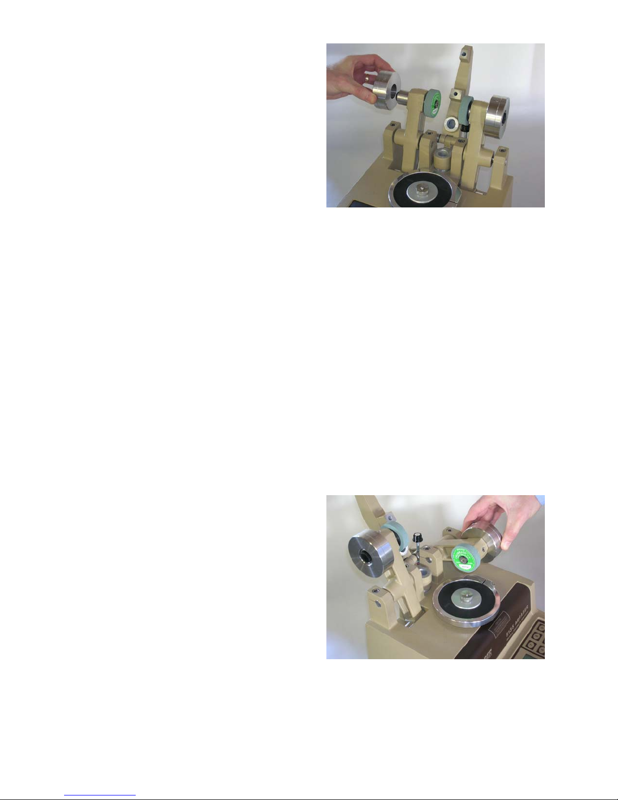
Mounting the Abrading Wheels
A feature of the model 5135 / 5155 is the Quick
Release Mounting Hub. Utilizing an expanding
collet hub, Genuine Taber wheels are quickly
mounted to the abraser. A spring loaded,
19 5135 / 5155 Operating Instructions ver 1.1
Figure 50
To mount a wheel, press the push button
located at the end of the auxiliary weight mount.
This will release the beveled retaining nut
enabling the collet to contract. With the label
facing toward the center of the turntable,
carefully slide the wheel all the way onto the
mounting hub. Release the push button. The
hub retaining lip will secure the wheel until it is
disengaged.
Periodic cleaning of the mounting hub and
Page 21
flange with the S-12 brush is recommended to
prevent the accumulation of particles and other
debris. Any build up of loose debris may
prevent the wheel from being mounted properly.
NOTE: When not in use, wheels should be stored in
their original containers to prevent damage.
Wheel Loading (Auxiliary Weights)
With no auxiliary weights, each abraser arm
applies a load of 250-grams against the
specimen. In addition to the mass of the
abrading arm itself (250 grams), precision
stainless steel weights are included to provide
standard wheel loads of both 500 and 1000
grams. For simplicity sake, each weight is
marked with the total load that will be exerted on
the wheel. The weights marked 500 grams are
actually 250 grams. Likewise, the weights
marked 1000 grams are 750 grams.
Counterweights are also available to further
expand the range of wheel loads, and may be
used in conjunction with the standard weights.
Available in 125 gram or 175 grams,
counterweights are applied to the mounting stud
found on the back of the abraser arm.
One of three standard wheel loads is normally
specified in the test method – 250 grams, 500
grams, or 1000 grams. This reference is per
arm (not combined), see Figures 6 – 9.
• When it is necessary to operate at less than
the 250-gram load, counterweights of 125
and 175 gram are available.
• To operate in the 250-gram range, no
additional weights are used.
Figure 51
NOTE: The marking of the auxiliary weights indicates
the total of both the weight and the abrading arm.
NOTE: The load that is specified in most test
methods does not include the mass of the wheel.
NOTE: To eliminate the mass of the abrading wheels,
place a second pair of wheels on the counter weight
studs located on the rear of the abraser arms.
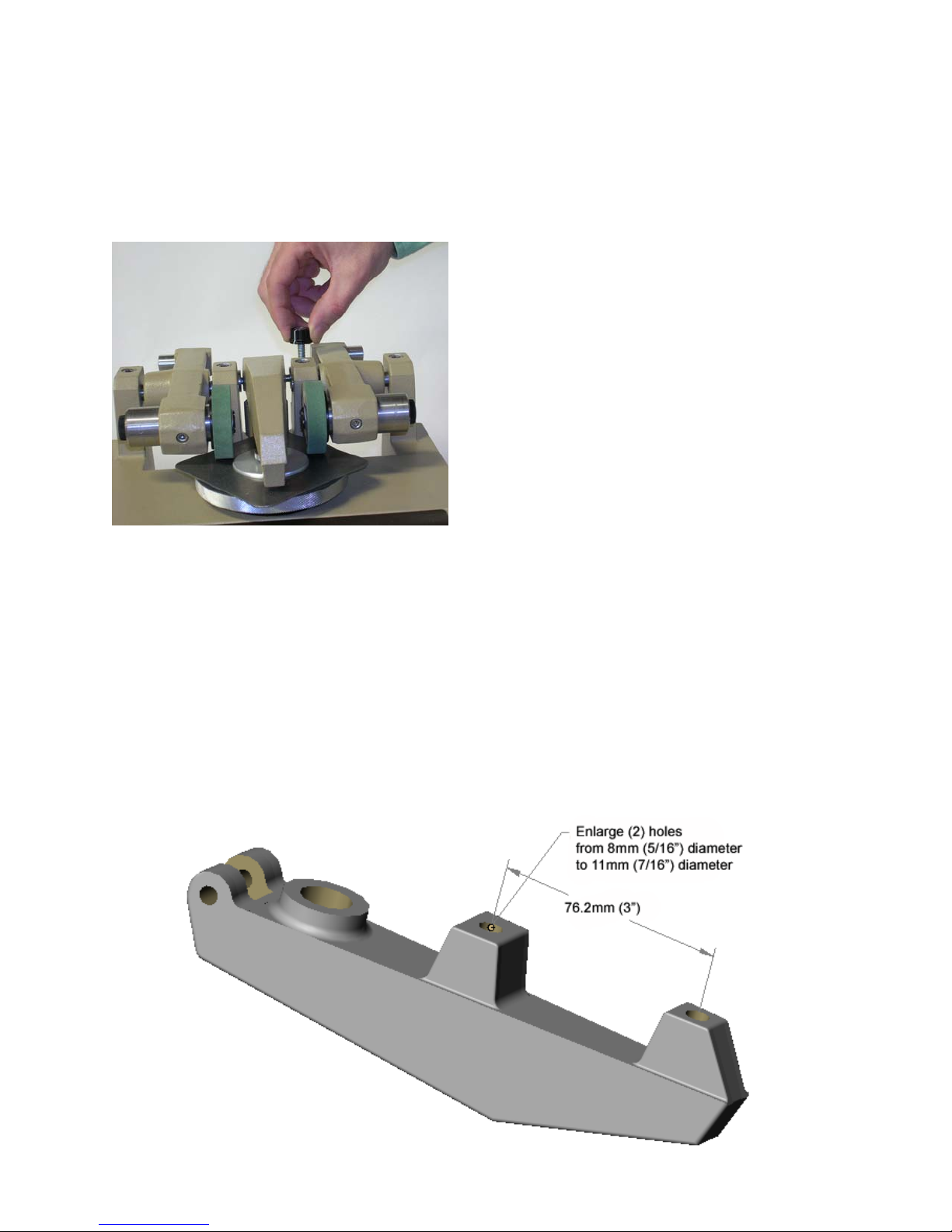
Lowering the Abrading Heads
Prior to conducting a test or refacing Genuine
Taber wheels, the abrading heads must be
lowered onto the surface of the specimen.
Firmly grip each arm and lower them from their
upright position.
When using the 5155 Abraser, if only one
turntable is utilized, the abrading arms not being
used should be raised to their upright position
and the vacuum nozzle not being used should
be in the down position.
• To operate in the 500-gram range, slide an
auxiliary weight marked 500 grams onto
both the left and right auxiliary weight
mounts (found opposite of the wheel
mounting assembly).
• To operate at 1000 grams, slide the auxiliary
weights marked 1000 grams onto the
auxiliary weight mounts.
If no wheel loading is specified in the test
method, an appropriate load may be determined
through experimentation. As a basic rule of
thumb, a minimum number of test cycles should
be completed before the end point occurs (i.e.
300 cycles). Otherwise, the load may be too
heavy. The section Characteristics of Abrading
Wheels found on page 21 provides additional
information should there be any load restrictions
for the abrading wheel you are using.
20 5135 / 5155 Operating Instructions ver 1.1
U WARNING: Dropping an abraser arm onto the
specimen table may cause misalignment and
consequent inaccurate test results.
Figure 52
Page 22
Adjusting the Height of the Vacuum
Pickup Nozzle
After the specimen has been mounted, the gap
between the vacuum pickup nozzle and
specimen surface should be set. It is extremely
important that the height of the suction nozzle be
adjusted properly, especially when evaluating
specimens of different thicknesses.
Figure 53
The height of the vacuum pickup nozzle is
referenced in many test methods. If it is not, you
must consider the material being tested. For
most materials, a gap of 6.35 mm
sufficient. However, a setting of 3.17 mm
has been found to be more effective on
inch)
certain rigid materials.
To adjust the vacuum nozzle height, first lower
the vacuum pickup nozzle from its rest position.
A precision adjustment knob located next to the
nozzle is used to adjust the distance between
the nozzle and specimen. Each full rotation of
the knob represents a 1.27 mm
(0.25 inch) is
(0.125
(0.05 inch) height
adjustment.
NOTE: To facilitate resetting the nozzle for a
given thickness of material, a shim may be inserted between
the nozzle and specimen, provided care is taken not to
damage the specimen surface.
Setting the Vacuum Level
The vacuum suction level should be set high
enough to remove debris from the specimen
surface, but not lift flexible samples. A visual
inspection of the wear path can usually indicate
if debris is adhering to the specimen surface and
the vacuum level (or vacuum pick-up nozzle
height) needs to be adjusted. For test control
and standardization of vacuum suction, the
vacuum level is calibrated to values of 50 –
100%.
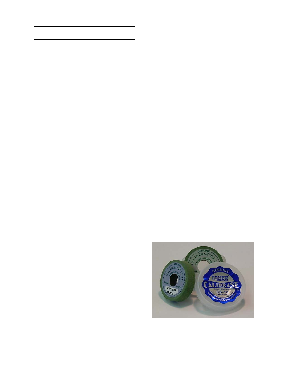
Modified Vacuum Pick-up Nozzle
A modified vacuum pick-up nozzle is available
for materials that are evaluated using a change
in haze. It has been found that many materials,
such as transparent plastics, may generate
static electricity during testing resulting in an
attraction of loose grit and debris to the
specimen surface. The orifice openings of the
modified vacuum pick-up nozzle are 11 mm
(0.4375 inch) opposed to the nominal opening of 8
(0.3125 inch). This assists with the removal of
mm
debris that has adhered to the specimen as a
result of this static attraction.
If transparent materials are the only material that
you intend to test with your Taber Abraser, you
may elect to permanently modify the vacuum
pick-up nozzle (see below diagram).
21 5135 / 5155 Operating Instructions ver 1.1
Page 23
CHARACTERISTICS OF ABRADING
WHEELS
The choice of which Genuine Taber abrading
wheels to use is best determined by preliminary
testing on the material to be investigated. The
abrasive action of the testing wheel should
reproduce, as nearly as possible, the wear that
the material will receive in actual use. It is
important to keep in mind that wear is a complex
phenomenon that may not be exactly replicated
through an accelerated abrasion tests.
Abrading wheels for the Taber Abraser can be
classified as:
®
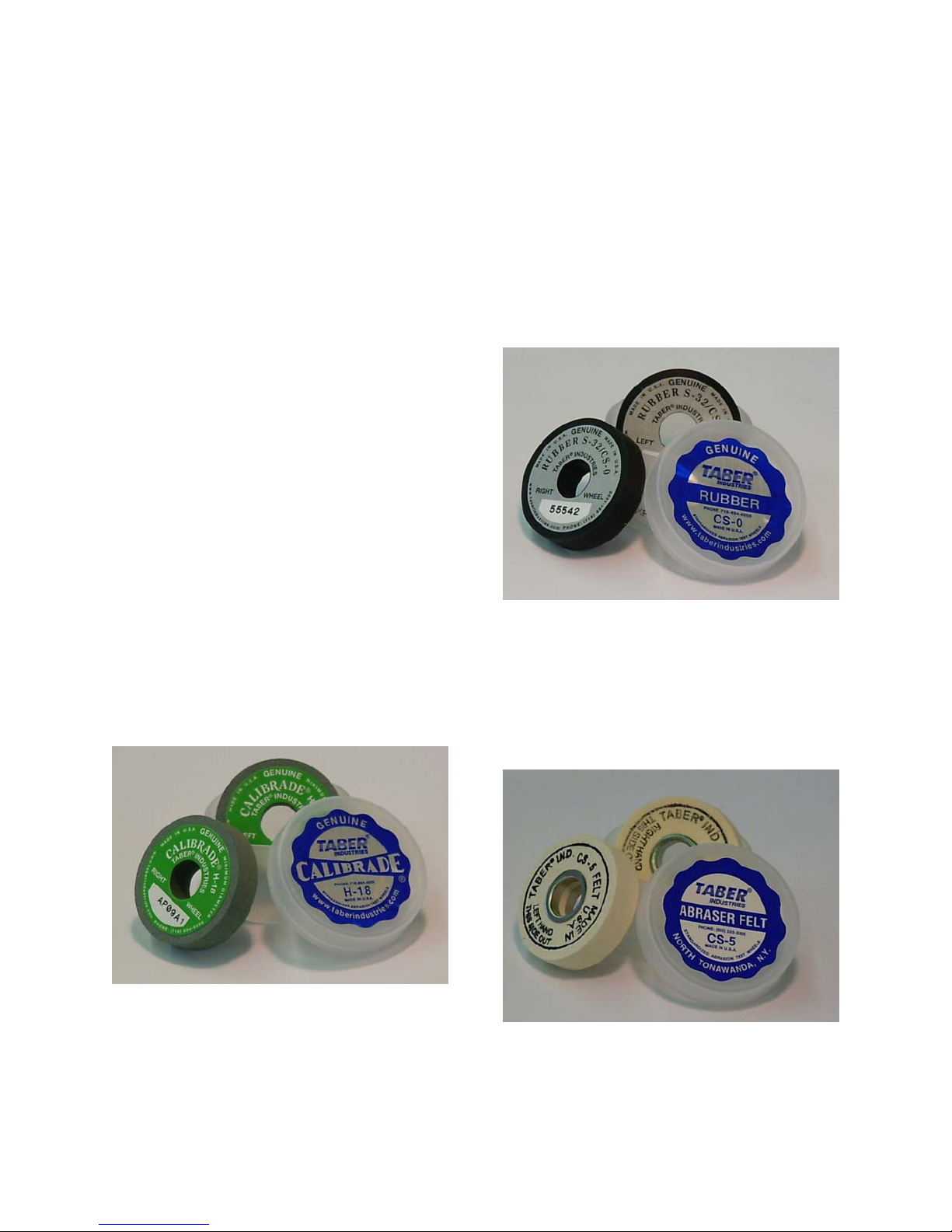
Calibrase
resilient binder and aluminum oxide or silicon
carbide abrasive particles. Frequently used
to evaluate rigid specimens.
Calibrade
composed of a vitrified (clay) binder and
silicon carbide or aluminum oxide abrasive
particles. Frequently used to evaluate
flexible specimens.
Specialty – Used for special applications.
For both Calibrase and Calibrade wheels,
different grades are furnished to meet varying
requirements of abrasive action. During testing,
the wheel surface gradually wears away
exposing new abrasive particles. The minimum
usable diameter of Taber abrading wheels is 13/4 inch, which corresponds with the wheel
label.
The composition of Genuine Taber abrading
wheels has been carefully chosen to reproduce
normal service wear. The quality and uniformity
of these wheels is maintained by continuous
inspection sampling and tightly controlled
manufacturing processes.
– A resilient wheel composed of
®
– A non-resilient wheel
Calibrase Wheels
CS-10F Calibrase – A resilient wheel that offers
a mild abrading action, and was designed to
operate under loads of 250 or 500 grams. The
CS-10F is typically used to test materials such
as safety glazing materials and transparent
plastics, and must be refaced with the ST-11
refacing stone.
CS-10 Calibrase – Similar to the CS-10F, this
resilient wheel offers a mild – medium abrading
action like that of normal handling, cleaning, and
polishing. This popular wheel has been used to
evaluate a variety of materials including organic
coatings, plastics, textiles, leather and paper
products. Reface with the S-11 refacing disc.
CS-10P Calibrase – The abrasion rate is the
same as the CS-10, but this wheel has been
engineered so the wheel surface does not load
when testing paper products. Intended for tests
of short duration, with refacing after every tenth
test.
CS-10W Calibrase – This wheel is the same as
the CS-10 but white, to eliminate any color
transfer from the wheel to the specimen.
CS-17 Calibrase – Compared to the CS-10
wheel, the CS-17 produces a harsher abrasion.
Normally operated using loads of 500 or 1000
grams, this wheel is useful for testing materials
such as ceramics, plastics and enamels.
Reface with the S-11 refacing disc.
NOTE: Custom formulations can be developed
specific to your application.
U WARNING: Because of possible deterioration,
Calibrase wheels should NOT be used after the
expiration date printed on the wheel.
NOTE: The wear life of Calibrase or Calibrade
wheels will vary based on the load, surface texture
and frictional characteristics of the material tested and
frequency of refacing.
NOTE: The abrasive coefficient of the wheels can be
altered by oil or other contaminants. Handle only the
sides of the wheels.
U WARNING: Shelf life is dependent on proper
storage conditions (temperature 23°C±2°, relative
humidity 50 ±5%). When not in use, store
abrading wheels in their original container.
22 5135 / 5155 Operating Instructions ver 1.1
Figure 55
Page 24
Calibrade Wheels
Specialty Wheels / Abradants
H-10 Calibrade – A non-resilient, vitrified wheel
designed to evaluate steel and ferrous alloys for
resistance to abrasion. It has also been used, to
test the effect of hardening and tempering
treatment on steel and other ferrous materials.
The H-10 Calibrade wheel should be used with
either 500 or 1000 gram loading.
H-18 Calibrade – This commonly used non-
resilient wheel provides a medium coarse
abrasive action. It is most often used to
evaluate resilient materials such as rubber (nontacky), certain woven textile fabrics, coated
fabrics, and flexible plastic sheets.
H-22 Calibrade – The H-22 wheel produces a
coarse abrasion. It has been used to test
rubber, linoleum, leather, deep pile fabrics (such
as automobile floor coverings) and concrete.
H-38 Calibrade – A non-resilient, vitrified
abrading wheel comprised of fine abrasive
particles. Designed to operate with 250 or 500
gram loads, the principal use of this wheel is to
test woven and non-woven fabrics. Must be
refaced using the Taber Wheel Refacer and
multi-point diamond tool.
Custom Formulations – To inquire about
custom wheel formulations, please contact
Taber Industries.
CS-0 – A resilient wheel containing no abrasive
particles. Intended for use when a very mild
abrasive action is required, or for wet tests such
as determining the relative abrasion of dental
pastes, cleaning powders, or similar
compounds. Adhesive sandpaper strips can be
adhered to the periphery of the CS-0 wheel to
evaluate the abrasion resistance of highpressure decorative laminates.
NOTE: Calibrade wheels do not have an expiration
period.
U WARNING: Calibrade wheels are diamond trued
at the factory and can be used continuously
without further refacing until the abrading
surfaces show indications of becoming worn out
of round, crowned or clogged. When refacing is
required, a wheel refacer must be used.
Figure 56
Figure 57
CS-5 – This abrading wheel is manufactured
from a densely compacted wool felt. Designed
to be tested at 250 or 500-gram loads, its
principal use is in testing textile fabrics when the
service wear requires one fibrous material to rub
against another.
Figure 58
23 5135 / 5155 Operating Instructions ver 1.1
S-32 – See CS-0.
S-35 – Manufactured out of tungsten carbide,
this periphery of the S-35 consists of sharp
Page 25
helical teeth (1 mm pitch x 45° spiral pitch
angle). The teeth combine both a cutting and
tearing action, which provides a very severe
abrasion. Intended for use only on resilient
materials such as rubber, linoleum, and leather.
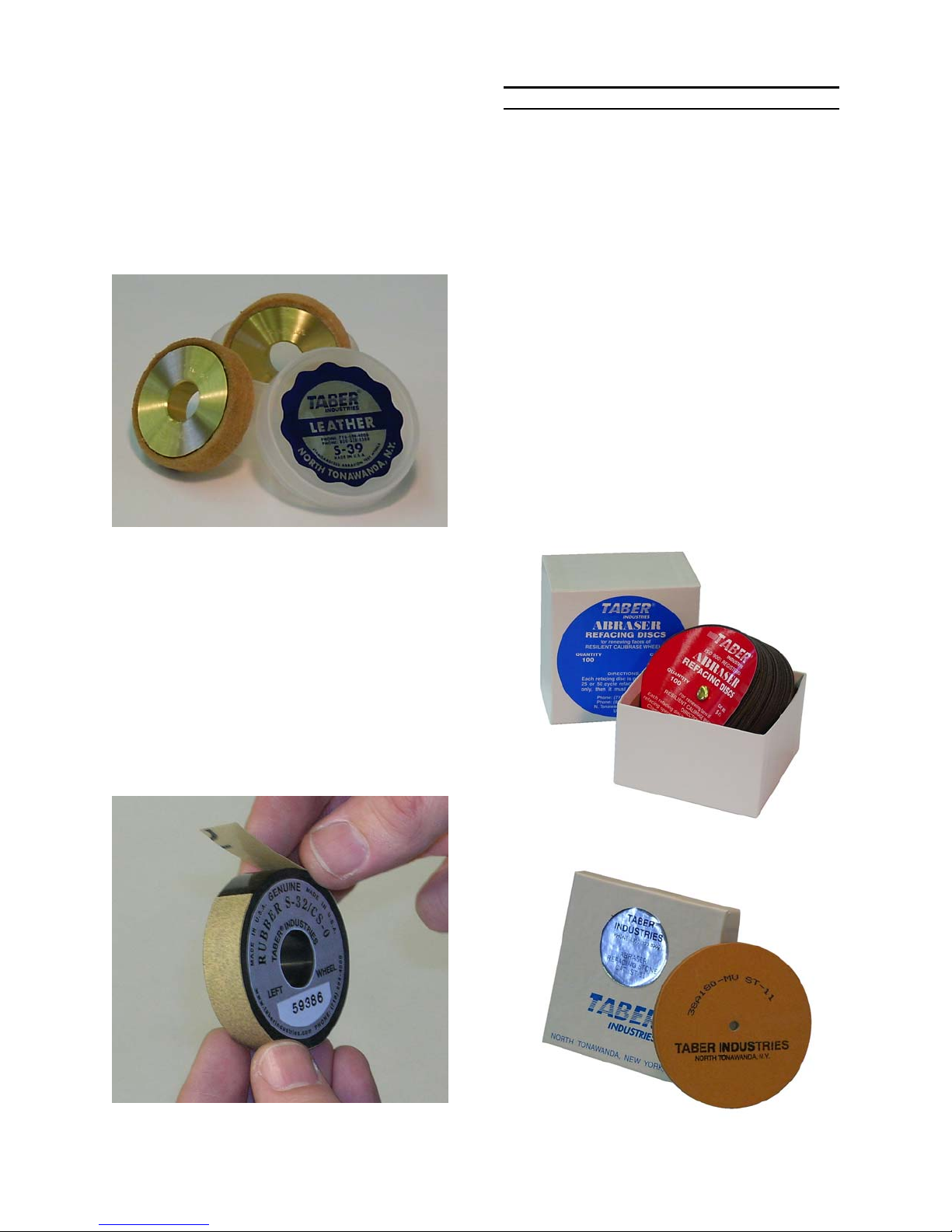
S-39 – This wheel is used in conjunction with the
Grit Feeder to conduct three-body abrasion
tests, and includes a leather strip that has been
adhered to exterior of a brass hub.
REFACING ABRADING WHEELS
Abrasion tests utilizing the Taber Abraser
require the abradant to be standardized prior to
the test. Failure to reface the wheel surfaces,
may introduce variation into the test results.
Depending on abradant type and material, the
wheel surface may change during the test (i.e.
become clogged) due to the pick up of debris or
other abraded material from the test specimen.
To standardize, the wheels must be cleaned
(refaced) at regularly defined intervals.
U WARNING: Wheels can be used until they are
worn down to their minimum diameter of 44.45 mm
(1.75 inch) O.D. as indicated by the wheel label.
Refacing Resilient Wheels (Calibrase)
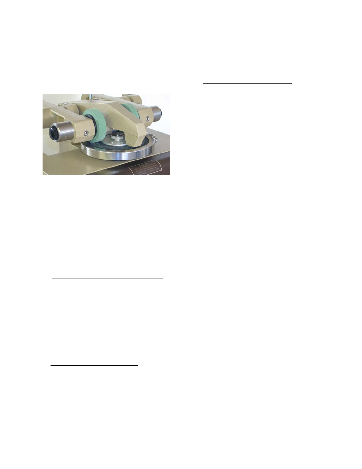
The S-11 Refacing Disc (Figure 61) should be
used to resurface all Calibrase wheels with the
exception of the CS-10F. The CS-10F wheel
should be refaced using the fine side of a ST-11
Refacing Stone (Figure 62).
Figure 59
S-33 – A 12.7 x 165 mm (0.5 x 6.5 inch) strip of 360
FEPA closed coat sandpaper that includes a
pressure sensitive adhesive used for attaching
the strip to the periphery of S-32 (CS-0) resilient
wheels. To maintain the rate of abrasion, the
sandpaper strips must be changed after a
defined number of test cycles (typically 200 or
500).
S-42 – Same description as S-33, but 180 ANSI-
CAMI open coat.
Figure 61
Figure 60
24 5135 / 5155 Operating Instructions ver 1.1
Figure 62
Page 26
A. Breaking in New Wheels – Calibrase wheels
are diamond trued before leaving the factory,
however their resilient composition makes them
subject to slight changes of form. Before a new
pair of Calibrase wheels is put into service, the
wheels must be given two refacings of 50 cycles
each. This will break in the wheels, and ensure
perfect contact of the abrading faces with the
specimen surface.
Figure 63
NOTE: The S-11 Refacing Disc is used only once
(maximum of 50 cycles), therefore this initial refacing
of new wheels will require two (2) Refacing Discs.
NOTE: The useful life of the ST-11 Refacing Disc is
10,000 cycles (approximately 400 refacings).
U WARNING: Never reface wheels with a used S-11
refacing disc. Unless new S-11 refacing discs are
used for each refacing, the wear coefficient of the
wheel faces may change and inject an error in the
test results.
B. Testing with Previously Used Wheels –
Before each test, reface previously used wheels
25 or 50 cycles. Twenty-five cycles is sufficient
when the previous test was a short one on
similar test material. Fifty cycles is
recommended when the previous specimen was
of an unlike material or the test was of 1000
cycles or more.
NOTE: Wheels that have not been used for a long
period of time may require two break-in refacings like
a new set of wheels.
C. Refacing Wheels During a Test – Calibrase
wheels are designed to operate continuously
throughout the test without additional refacing.
However, there may be times when the wheel
faces tend to become clogged due to the
adhesive character of particles worn off the
specimen. Should this happen, re-standardize
the abrading surfaces by running them 25
cycles, then proceed with the test. Do not
confuse coloring of the wheels with “clogging” as
this is simply due to the wheel faces becoming
coated with fine abradings, a condition that must
be expected.
NOTE: For most materials, it is usually not necessary
to reface wheels prior to 1,000 cycles of testing. In an
extreme case it may be necessary to reface the
wheels every 500 cycles.
D. Truing Out-of-Round Wheels – It is
important that abrading wheels run true to obtain
accurate test results. Out-of-round wheels may
be detected by an up and down movement of
the abrading arm during testing. To reface
resilient Calibrase wheels when they become
worn out of round, follow the procedure for
refacing vitrified Calibrade wheels.
U WARNING: Truing Calibrase wheels on the
diamond refacer removes most of the abrasive
grain from the wheel faces. In order to reestablish their normal abrasion coefficient, they
must be given two refacings of 50 cycles each
(follow the procedure for breaking in new wheels).
Procedure for Refacing Calibrase Wheels
• Apply the wheels to the Abraser on the
corresponding quick-release mounting hub.
When facing the abraser, the right (left)
wheel will be mounted on the right (left)
abraser arm such that the wheel label is
facing inward towards the center of the
specimen table.
• Mount an S-11 Refacing Disc (ST-11
Refacing Stone) on the E100-125 specimen
holder. To secure the S-11, use the clamp
plate and nut, and clamp ring. The clamp
plate and clamp ring are not required for the
ST-11 refacing stone.
• Weight the abrading arm with the same load
weight that is to be used for testing.
• Lower the abrading wheels onto the refacing
medium.
• Lower the vacuum pick-up nozzle and adjust
its height to within 3.175 – 6.35 mm
0.25 inch)
below for CS-10F wheels.)
• If you are using a vacuum suction level less
than 100, program the appropriate value. It
is recommended that the vacuum level not
be less than 70 for wheel refacing.
• Program the appropriate number of cycles
according to Table 1.
• Using the S-12 Brush, frequently remove the
abradings by brushing the refacing medium
during the refacing operation. DO NOT
brush the wheels.
of the refacing disc. (See note
(0.125 –
25 5135 / 5155 Operating Instructions ver 1.1
Page 27
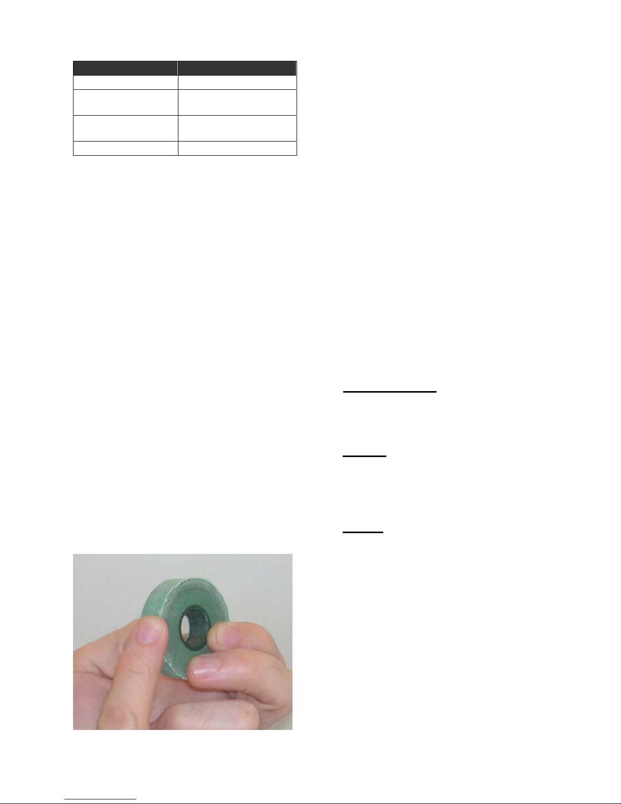
TABLE 1
Wheel Status Refacing Cycles
New 2 refacings of 50 cycles
Used (previous test
<1,000 cycles)
Used (previous test
>1,000 cycles)
* During Test 25 cycles
25 cycles
50 cycles
NOTE: When refacing CS-10F wheels, adjust the
vacuum pick-up nozzle to 0.79 – 1.59 mm (0.0312 –
0.625 inch) above the ST-11 refacing stone.
NOTE: Properly refaced wheels must contact the
specimen their full width. Refacing can be checked
visually, wheel color should be uniform after two
refacings of 50 cycles each. If it is not, reface the
wheels a third time.
U WARNING: Do not reface Calibrase wheels by
placing a S-11 refacing disc over the specimen.
Mounting on top of a specimen may cause the
surface of the S-11 not to run absolutely true,
which would abrade a slight crown on the wheel
faces causing inaccuracies.
Wear Characteristics of Calibrase Wheels
Resilient wheels possess properties that cause
the working faces to disintegrate slowly as they
are used, continually exposing fresh abrasive
grains to the specimen being tested. This
characteristic is necessary for the proper
functioning of the Abraser.
A thin film of rubber may form on the left hand
edge of Calibrase wheels as the main body of
the wheel wears down (Figure 64). Although a
narrow fin is not detrimental to the test, should it
extend more than 1.59 mm
the work surface, remove it by gently rubbing the
edge with your finger. Do not rub excessively so
as to round the edge of the wheel.
(0.0625 inch) beyond
Wear life of Calibrase wheels varies with the
surface texture and frictional characteristics of
the material tested, in addition to the load.
Under ordinary conditions Calibrase wheels
should give from 10,000 to 50,000 wear cycles.
Abnormally short wheel life indicates use of the
wrong wheel, load, or procedure for the material
tested, or too frequent refacing.
U WARNING: The abrasive coefficient of the
working faces of the wheels can be altered by oil
or moisture from the fingers. Touch only the sides
of wheels in handling.
Refacing Vitrified Wheels (Calibrade)
All Calibrade wheels are diamond trued at the
factory and may be used continuously without
further refacing until the abrading surfaces show
indications of becoming worn out of round,
crowned or clogged with abraded material.
Refacing is also advised when starting a series
of comparative tests or changing to an entirely
different material. In some instances, where
there is a tendency for the working surfaces of
the wheels to pick up excess material, it may be
desirable to reface the wheels before testing
each specimen. (This latter procedure is only
required in exceptional cases.)
A. Worn out of round
become out of round due to unevenness of the
specimen being abraded or other reasons. The
normal abrading surface of these wheels should
be concentric with the hub.
B. Crowned
that are “crowned” appear slightly rounded. To
check for this condition, place a straight edge
against the two wheels. The straight edge
should be in contact with the full width of the
wheels.
C. Clogged
spot buildup on the working faces of the wheels
and should not be confused with the uniform
coloring of abrading dust from the specimen.
– The working surfaces of wheels
– “Clogging” can be identified as a
– Occasionally, wheels
Figure 64
26 5135 / 5155 Operating Instructions ver 1.1
Procedure for Refacing Calibrase Wheels
To properly reface Calibrade wheels, a Taber
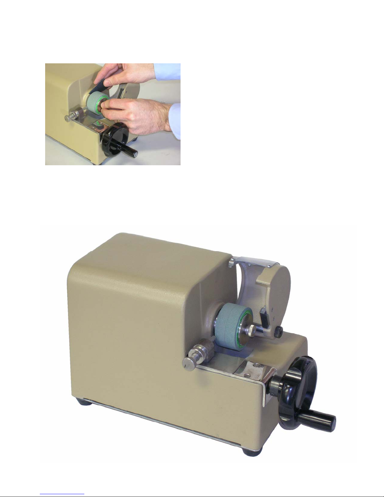
Wheel Refacer must be used. This instrument
utilizes a diamond tool that is traversed across
the working surface to precision dress the
abrading wheels (Figure 66).
Refacing Calibrade wheels leaves a sharp edge
that may sever threads when testing textile
fabrics. It is acceptable to remove this sharp
edge prior to testing. To do so, cut a small strip
from an S-11 refacing disc and hold it lightly
against the outer edge of each wheel. Manually
turn the nut to rotate the motor shaft. Reverse
Page 28
the wheels on the arbor and round the opposite
corners. Only the extreme sharpness of the
edges should be removed. A radius of 0.4 mm
(0.016 inch) is sufficient.
Figure 65
U WARNING: The abrasive coefficient of the
working faces of the wheels can be altered by oil
or moisture from the fingers. Touch only the sides
of wheels in handling.
27 5135 / 5155 Operating Instructions ver 1.1
Page 29

SECTION II
Testing with the Taber Abraser
SIGNIFICANCE AND USE
The Taber Rotary Platform Abraser is commonly
used to provide comparative data regarding the
abrasion resistance of a material.
It is important to recognize there may be several
factors that contribute to wear performance of
materials in actual use. Before predictions can
be drawn from laboratory tests, actual end-use
trials should be conducted. This helps establish
the relationship between the laboratory abrasion
test and actual wear in the intended end-use.
The consideration of additional factors is often
necessary in the calculation of predicted
durability from specific abrasion data. While
“abrasion resistance” (often stated in terms of
the number of cycles to produce a specified
degree or amount of abrasion) and “durability”
(defined as the ability to withstand deterioration
or wearing out in use, including the effects of
abrasion) are frequently related, the relationship
typically varies with different end uses.
Accelerated abrasion tests compress the life
span of a product into a much shorter duration in
a controlled and monitored environment. While
the test may not represent the actual conditions
materials are exposed to, lab tests can duplicate
many real world conditions, making it much
easier to reproduce the test. In addition, there is
greater flexibility with the methodology, costs are
significantly less, and you are able to test more
samples.
TESTING PROCEDURES
As you start your testing, use of these guidelines
should assist you in developing a test procedure
that will yield reproducible test results, accurate
within the variations of quality inherent in the
material itself.
Establishing a Test Procedure
The purpose of this section is to outline all the
elements of a typical test procedure from
analysis of the testing problem to final evaluation
of results. Knowledge of the mere mechanics of
testing, the preparation and mounting of
specimens, and the setup and operation of the
Abraser is presumed. That phase of testing has
been treated in detail in other sections of this
manual. Where it is appropriate, reference will
be made to those sections.
To aid in the establishment of test procedures,
the following recommendations are offered. It is
important to recognize that these
recommendations may not apply to all variations
of materials and that modifications may be
required in performing a practical abrasion test.
They should not be construed as fixed test
specifications.
Analyzing the Test Problem – The value of the
Taber Abraser in research and control programs
depends to a considerable extent on the
operator’s knowledge of the test problem; the
service requirements and the desired wear
characteristics of the material examined.
Analyzing this problem before embarking on a
test series may save time and material. As
nearly as possible, the test should reproduce the
wear experience of the specimen in actual use.
The Test Environment – An environmentally
controlled test room is strongly recommended
where reproducible precision results are
required. Both heat and moisture affect the
abrasion resistance of most materials,
particularly organic materials. Abrasion
research projects are usually carried out in an
atmosphere maintained at 21 - 24°C
temperature and 50 percent relative humidity.
Without exception, samples to be tested should
be conditioned in the test atmosphere for at
least 24 hours – organic materials preferably for
48 hours or more. When research is conducted
to determine wear life under changing
atmospheric conditions, as in automobile and
aircraft materials, the atmosphere of the
laboratory is controlled accordingly.
(70 – 75°F)
NOTE: If an environmentally controlled test
laboratory is not available, test specimens should be
conditioned and tested with a minimum lapse of time.
U WARNING: When it is necessary to interrupt a
test of organic material for several hours, or
overnight, the sample should be discarded and a
new test begun. In the course of a few hours the
weight of a sample may change by moisture
Page 30

absorption or for other unexplained reasons.
U WARNING: Although the Abraser is designed to
operate at normal room temperature, it may be
used at temperatures as low as freezing. In
atmospheres approaching 0°C (32°F), allow the
motor to warm up until it reaches normal speed
before lowering the abrading arms. When the
Abraser is not in use, keep it in a room at normal
temperature.
Determining the Test Procedure – Standard
test procedures for a number of materials have
been established and, in the interest of
uniformity and the ready exchange of
information, are very generally accepted. To
ensure that test results will be comparable, the
procedure described should be followed exactly.
In the absence of a standard specification, the
technician must work out his or her own test
procedure. They may begin by referring to the
general recommendations for various materials
shown on pages 32 - 37. Final choice of
abrading wheels, load weights, method of
mounting the sample, kind and duration of test,
and other details may best be decided by
preliminary testing of the specimen material.
Begin by estimating the nature and degree of
wear that the specimen would receive in actual
service. Select an abrasive wheel that will most
nearly reproduce this wear, but will not clog with
the material being tested. Past experience must
guide in choosing the load weight. Under
ordinary conditions a load and wheel
combination should run on a specimen a
minimum of 300 cycles before the end point
occurs, otherwise the test may be too harsh. In
certain instances there may be exceptions to
this rule since there are many varieties of
material that can be tested with the Abraser.
When setting up a test procedure, always keep
in mind to avoid wearing the material too fast as
this will result in ripping and tearing action.
Recording the Test Procedure – It is essential
that careful record of every phase of the test
procedure be kept for purposes of comparison.
This will also enable others to duplicate the test
at a later date. An example of a standard form
for test record is shown on page 48.
Selecting the Method of Evaluating Test
Results – Test results are commonly expressed
as a wear factor or numerical abrasion index of
the test specimen. The most common methods
for calculating this index are by measuring a
visual or physical change. It should be noted
that the wear factor arrived at by any one of the
following four methods is not directly
comparable.
METHOD OF EVALUATION
A single test may correctly indicate the
material’s resistance to abrasion, but it should
not be accepted as a final answer. A minimum
of three to five tests should be made of any
given material and the average result taken to
represent the true value.
A. Visual End Point Method – Certain
materials are best adapted for testing to a
clearly marked change in appearance or
physical breakdown of the specimen. This is
especially true of materials with a plated, glazed,
polished, or printed surface where the end point
is sharply indicated; of materials that withstand
less than 300 abrasion cycles before reaching
the end point of test; and of textile materials.
The visual method is a subjective test that
requires examination of the test specimen, and
should be conducted under controlled lighting.
The test results will be a description of the wear,
and must be as thorough as possible to ensure
all the details of the wear mechanism are
captured. For example if the test specimen is a
coating, one suggestion is to monitor when the
surface coating has worn down enough so that
the substrate material is visible (this is defined
as ‘breakthrough’). For printed specimens,
breakthrough is when a portion of the printing
has fully worn away. Breakthrough testing
should be quantified by recording the number of
cycles it took for breakthrough to occur.
Other examples of Visual End Points:
1. Loss of Luster
2. Changes of Surface Appearance
3. Color Changes
4. Appearance of a Hole
Another option is to compare the abraded
specimens with a measured abraded standard.
A rating scale of 1 – 5 is commonly used to
assist with this type of evaluation, and often
includes a photograph depicting each ranking.
B. Weight Loss Method
method is a quantifiable method in which you
record the weight loss of your test specimen due
to abrasion. To perform this method, you will
need to have access to a precision balance,
preferably one that can measure to the milligram
range since some tests may yield very low
weight loss. Weigh your test specimen before
and after testing to obtain your initial and final
weight values. The difference between these
two values will be your weight loss.
– The weight loss test
29 5135 / 5155 Operating Instructions ver 1.1
Page 31

Wt
= A – B
Loss
Where,
A = weight of test specimen before abrasion
B = weight of test specimen after abrasion
When performing this method, loose particulate
may adhere to specimens during testing and
handling. It is critical that you clean off the test
specimens as best as possible with a lint-free
cloth or by lightly brushing prior to weighing. If a
sample has been wet tested or if an indicator
has been used, ensure the specimen is
thoroughly dried. If static electricity affects the
specimen, a static eliminator (such as
STATIKIL) may be sprayed on both sides prior
to taking the final measurement.
This method of evaluating test results is
recommended when the results are to be
compared with those of similar materials having
nearly the same specific gravity. The Taber
wear index (rate of wear) is the loss in weight in
milligrams per thousand cycles of abrasion for a
test performed under a specific set of conditions.
The lower the wear index, the better the
abrasion resistance quality of the material.
For example: if a specimen is abraded 5000
cycles and loses 500 milligrams of material, the
wear index should be 100. Likewise, a material
that withstood 500 cycles of abrasion and lost
only 100 milligrams of material would have a
wear index of 200.
EXAMPLE:
500 mg. X 1000 cycles
5000 cycle test (Weight Loss Method)
100 mg. X 1000 cycles
500 cycle test (Weight Loss Method)
= 100 Taber Wear Index
= 200 Taber Wear Index
U WARNING: When using a mounting card, ensure
the cards have been conditioned with the test
specimen. Take the weight measurement A FTER
the specimen has been affixed to the mounting
card.
C. Volume Loss Method – In comparing the
wear resistance of materials having different
specific gravities, a correction for the specific
gravity of each material should be applied to the
weight loss to give a true measure of the
comparative wear resistance. The use of this
correction factor gives a wear index related to
the loss in volume of the material to which it is
applied.
For illustration, consider a hypothetical case
where it is desired to compare the wear
resistance of an aluminum die casting material
with the wear resistance of a similar zinc
material. In this case, three specimens, 100 mm
(4 inch) square by 6.35 mm (0.25 inch) thick, of
each type of material are prepared so that an
average result can be obtained. Each test
specimen is run 5000 cycles, using a CS-17
wheel operating under 1000 gram load. For
purposes of illustration, assume that both the
aluminum and zinc samples showed a weight
loss of 860 milligrams. It would appear that the
materials have equal resistance to abrasion
since their weight loss was equal, however since
aluminum and zinc materials have different
specific gravities a correction factor must be
applied to give a true indication of the wear
resistance. In doing this, the aluminum material
evidences a much greater volume loss, as seen
by comparison of the wear factor:
EXAMPLE:
Aluminum
860 mg. X 1000 cycles
2.7 sp. Gravity x 5000 cycle test (Volume Loss Method)
Zinc
860 mg. X 1000 cycles
7.1 sp. Gravity x 5000 cycle test (Volume Loss Method)
= 63.7 Taber Wear Index
= 24.2 Taber Wear Index
When a clear organic coating is compared with a
heavily pigmented color coat, the latter will, of
course, have a much higher specific gravity as a
result of the added color pigment. It is
recommended that a correction factor be used
based on the amount of solids per gallon of the
liquid material.
D. Depth of Wear Method (Thickness)
–
Certain test requirements may call for measuring
the depth of wear after rotating the specimen a
given number of cycles under a specified
abradant pressure with a particular type of
wheel.
The depth of wear can be measured using an
Optical Micrometer or similar instrument. Place
the measuring device so that it spans both the
abraded and unabraded portion of the
specimen. Calculate the amount of wear by
measuring the difference between the abraded
and unabraded areas in four equal-distant points
around the specimen.
Alternatively, a thickness gage or micrometer
may be used. Mark four points on the back of
an unabraded sample, 90° apart and oriented 38
(1.5 inch) from the center hole [this will be
mm
within the wear path]. Using the measuring
device, determine the thickness and record.
After abrading the sample, repeat the
measurements and record the difference. To
compensate for depth differences around the
30 5135 / 5155 Operating Instructions ver 1.1
Page 32

specimen wear path, an average should be
computed from the four readings.
EXAMPLE:
0.003” Average Depth of Wear in 5000 Cycles
0.003” x 1000 cycles
5000 cycle test (Depth Method)
= 0.0006 Wear Factor
The specimen material, type of wheels used,
number of cycles, abradant pressure and
average wear depth are then recorded so that
specimen wear characteristics can be
compared.
E. Other Physical Change Methods
–
Performance specifications may be incorporated
when a material is used for a particular
application. For example, a tensile test might be
utilized before and after abrading a textile
webbing material that is used in the manufacture
of seat belts. A Burst test could be incorporated
in evaluating the abrasion resistance of a rubber
seal. Or, an air permeability test might be
included for medical packaging materials that
require the product be kept in a sterilized
environment.
SPECIMEN PREPARATION
Specimen Cleaning
Specimens should be cleaned in such a way
that the surface is free from grit, grease,
fingerprints or other contaminants. Since many
different kinds of materials can be tested, a
specific cleaning treatment cannot be given. If
contact with solvents or cleansers result in
changes to the material properties, surfaces
might be cleaned with isopropyl alcohol or a soft
cloth.
Specimen Conditioning
Prior to testing, it is recommended that
specimens be ‘conditioned’ for at least 24 hours
in the test atmosphere. Organic materials
should be conditioned for 48 hours. The drying
and curing conditions for printing or coating on
plastics versus metals can be different and may
influence the test results. Cure these specimens
under conditions specific to the material. Also,
heat and moisture are known to affect the
physical properties of many materials. It is
recommended that all tests be conducted in the
standard laboratory atmosphere of 23 ±2°C
with 50 ±5% relative humidity.
±3.6°F)
Rigid Materials
Rigid specimens are often cut from a larger
(73.4
sheet utilizing a cutting method appropriate for
that material. A 100 mm
is recommended with a 6.35 mm
(4 inch) square sample
(0.25 inch) center
hole.
Rigid materials are generally mounted to the
•
standard specimen holder without the Clamp
Ring (E100-102), and require a 6.35 mm
(0.25 inch) center hole. When using the S-21
Extension Nut, a 9.525 mm
(0.375 inch) center
hole is required.
• It is possible to test specimens without a
center hole by using S-37 or S-37-1
Mounting Sheets and the Drive Pin Type
Holder (E140-19).
• Specimens of uneven thickness should be
shimmed so that the top surface runs true.
A Ring Clamp Specimen Holder (E140-14)
or Threaded Ring Specimen Holder (E140-
21) can be used to test materials that are
slightly warped.
• To subject specimens to a wet abrasion test,
the Rimmed Specimen Holder (E140-75)
can be used. This is useful to determine the
effect of absorbed and / or surface moisture
on abrasion resistance.
• The recommended
6.35 mm
(0.25 inch). Using the S-21 Extension
Nut, specimens up to 12.7 mm
specimen thickness is
(0.5 inch) in
thickness can be evaluated. The Arm Height
Extension modification will permit testing up
to 40 mm
(1.57 inch) in thickness.
Flexible Materials
Most flexible materials can be cut to size using
the Taber Sample Cutter – Model 5000.
Manually operated, this bench top cutter uses an
industrial cutting blade to prepare an exact 107
(4.2 inch) diameter specimen. A punch lever
mm
evenly transfers force through a spring-loaded
clutch to punch a 6.35 mm
Textile materials may be prepared using
scissors [approximate size should be 135 mm
(5.25 inch) round or square]. To cut the center
hole, fold the sample twice and cut a small
portion of the resulting corner.
To mount the specimen, place the test specimen
on the holder with the side to be abraded facing
up. Lightly secure the clamp plate and nut in
place to hold the center of the specimen. Adjust
the clamp ring such that it is a snug fit, and
place it half way on the specimen holder. Draw
the fabric taut over the specimen holder by
pulling on corners and edges of fabric. Tighten
the clamp ring further, and push the ring all the
way down over the edge of the holder, thus
putting tension on the fabric as it is secured on
(0.25 inch) center hole.
31 5135 / 5155 Operating Instructions ver 1.1
Page 33
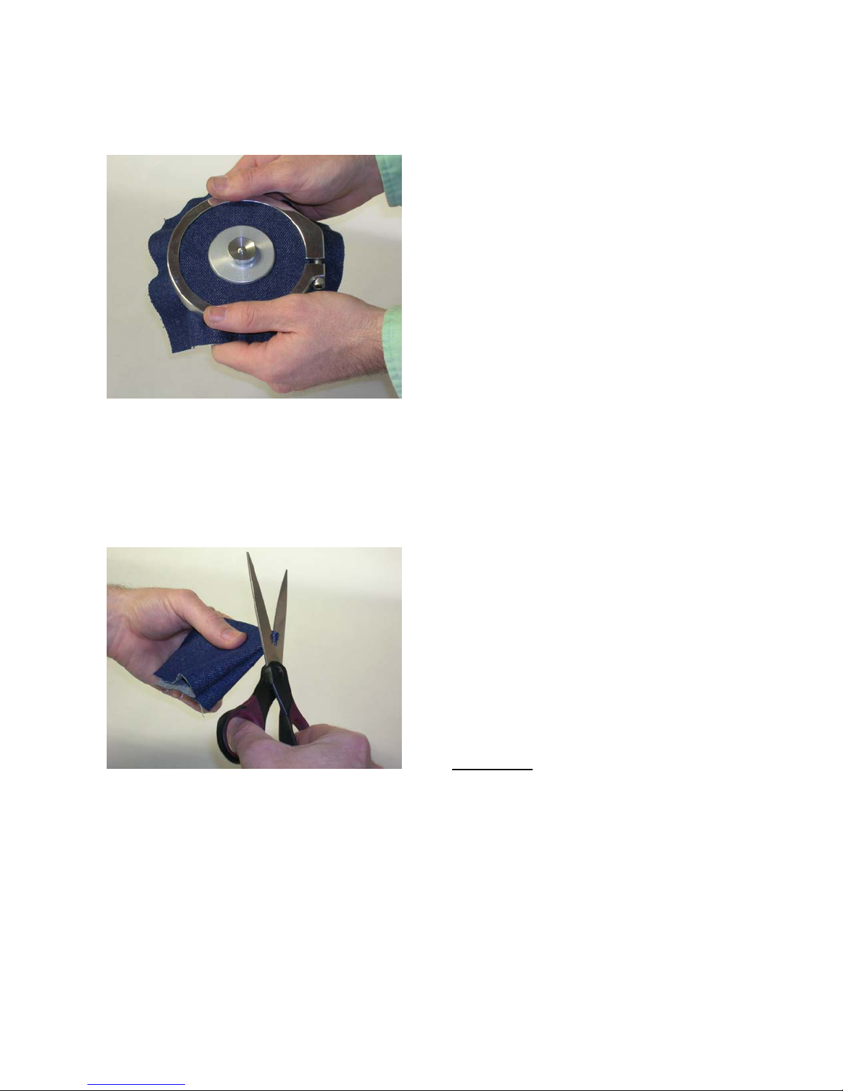
holder. Finish tightening the clamp plate and
nut, and finally tighten the clamp ring. Avoid
tightening to excess so as not to wrinkle the
specimen. Trim off any excess fabric around the
edges.
Figure 67
When it is desired to use abrasion test samples
for tests of other destructive agents such as
laundering, dry cleaning, and light, it is
recommended that the specimens be cut square
rather than round. The larger area of the square
provides for shrinkage in subsequent tests and
permits handling without touching the wear path.
down into the center recess.
• To prevent stretching or wrinkling of the
specimen during testing, flexible materials
can be mounted to the S-36 or S-36-1
Mounting Card. To prevent the vacuum
from lifting the specimen, it is advised to use
the clamp ring.
• To subject specimens to a wet abrasion test,
the Textile Holder, Tensioning Type for Wet
or Dry Testing (E140-18) can be used. This
holder is designed to give an initial stretch to
woven fabrics so that they may be tested
while moist with minimum tendency to
wrinkle. Alternatively, textile samples may
be adhered to a S-16 specimen plate. The
sample should be cut large and the corners
notched so that it will fold back over the
edges of the S-16 plate without build-up of
material. Take care to iron the folds at the
edges to form a flat, even testing surface.
• A transparent table (E100-10) may be used
for viewing textile specimens against a
strong light to determine the worn condition
of the threads without removing the fabric
from the holder. The E100-10 can also be
used with a small, high intensity light bulb
located beneath the specimen holder which
activates a photocell and electronic relay to
turn off the Abraser when the established
wear point is reached.
Figure 68
• Flexible materials are normally mounted on
the standard specimen holder with the
clamp ring. The E100-101 Specimen Clamp
will accommodate flexible materials up to
0.79 mm
(0.0312 inch) thick. The E100-102
Specimen Clamp will accommodate flexible
materials up to 1.59 mm (0.625 inch) thick.
• To generate useful data,
not be stretched or wrinkled
specimens must
. A Textile
Specimen Holder (E140-15) has a raised
wear track to give the fabric extra tension
when the ring is drawn down over the edge
of the holder and the clamp plate is drawn
Coatings
A coating that is representative of the coating
applied to actual product is required for
accurate, dependable results. Test panels
should be sprayed, drawn down or controldipped to achieve a uniform coating. Brush
application is not recommended where precision
results are desired. Paints, lacquers, and similar
coatings can be applied directly to specimen
plates available from Taber Industries:
Steel (S-16)
– S-16 plates (Figure 69) are
uniformly blanked from 20-gage auto body sheet
steel and dull finished for good adhesion of the
coating to the metal. The size is 100 mm
(4 inch)
square with rounded corners and a 6.35 mm
(0.25 inch) center hole.
NOTE: Before applying the coating, S-16 plates must
be thoroughly cleansed of dirt, grease or other
contaminants. Use of a solvent degreaser or other
solvent cleaner capable of dissolving and removing oil,
grease and solid particles is suggested.
32 5135 / 5155 Operating Instructions ver 1.1
Page 34
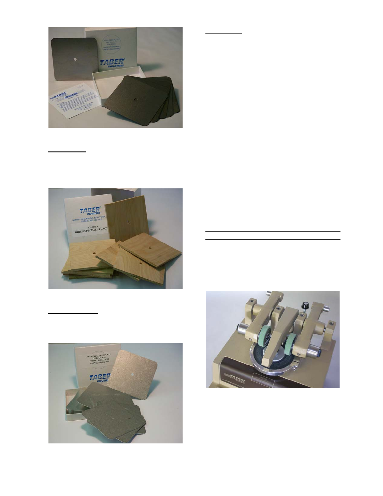
Figure 69
Glass (S-31) – The S-31 is a quality plate glass,
approximately 3.17 mm
with a 6.35 mm
(0.25 inch) center hole.
(0.125 inch) in thickness
Panels dipped or sprayed on both sides should
be marked with an “A” or “B” to identify the front
and back surfaces and their respective tests. An
extra heavy application may not dry with the
same physical properties as a light coating.
When preparing your own test panels, ensure
the sides are flat and parallel. A simple means
to check for flatness is to place a straight edge
across the test panel surface, and verify there is
no gap. Use a file to remove any burrs from the
center hole and edges.
Wood (S-17) – S-17 plaques (Figure 70) are
manufactured from grade A1, 6.35 mm
(0.25 inch)
birch plywood. Sanded on both sides, the size
is 100 mm
inch)
center hole.
(4 inch) square with a 6.35 mm (0.25
Figure 70
Aluminum (S-18) – Produced out of #19 gauge
5052 aluminum, S-18 plates (Figure 71) are 100
mm (4 inch) square with rounded corners and a
6.35 mm
(0.25 inch) center hole.
• To generate useful data, specimens must be
flat and have a uniform coating thickness.
• To subject specimens to a wet abrasion test,
the Rimmed Specimen Holder (E140-75)
may be used. This holder has a 9.5 mm
(0.375 inch) raised rim for retaining liquids
during test. Such tests might include paint
used to mark traffic lanes at busy
intersections, subjected to both wet and dry
abrasion in everyday use.
TEST PROCEDURES
The following suggestions are provided as a
starting point for using the Taber Rotary Abraser
to evaluate different materials. See page 47 for
a partial listing of internationally recognized test
methods that reference the Taber Abraser.
Figure 71
33 5135 / 5155 Operating Instructions ver 1.1
Figure 72
Prior to conducting any tests, the abrading
wheels should be prepared accordingly and a
consistent vacuum nozzle height should be used
(measured off the specimen surface). Other
factors to consider include specimen
conditioning, environmental conditions, vacuum
suction level, specimen cleaning, and test
cycles. Specimens must have a flat, even
surface and run true.
Page 35
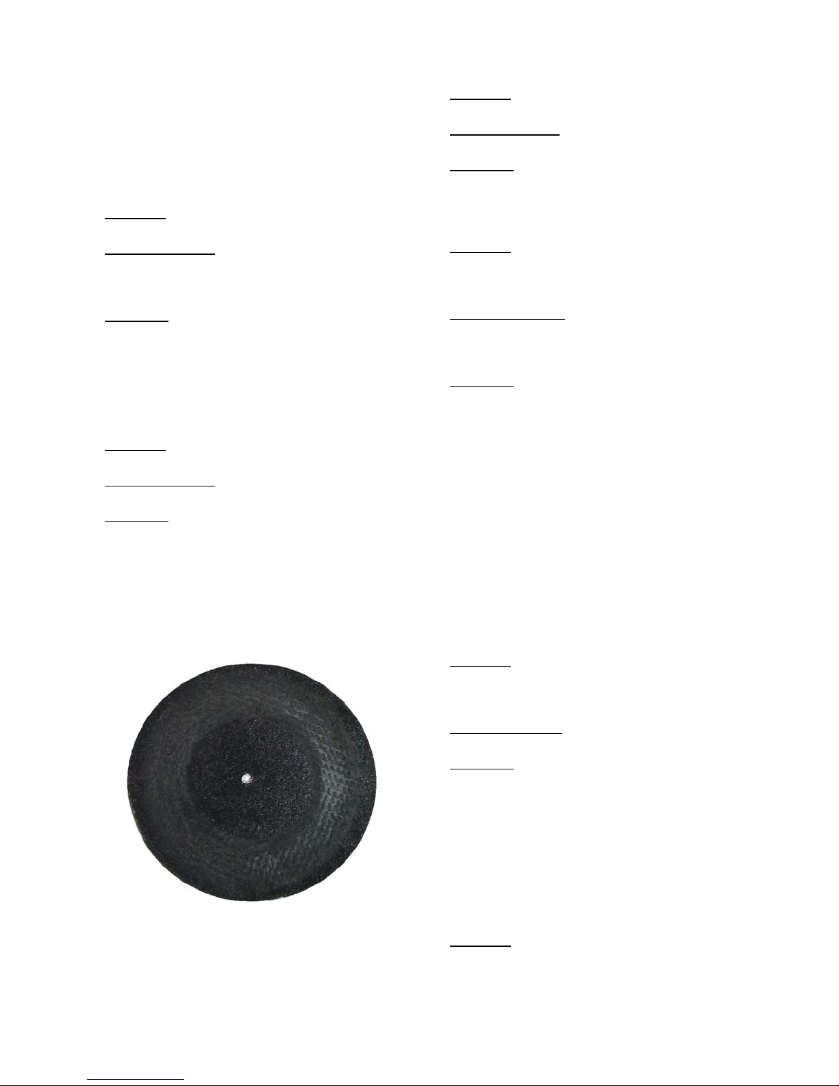
In the following procedures, it is assumed that
tests are conducted in an atmosphere controlled
to 50 percent humidity and 21 - 24°C
(70 – 75°F)
temperature. Also, samples are conditioned in
the test atmosphere for at least 24 hours before
testing.
Aluminum – Anodized Finish
Ceramic Finishes
Specimen: 100 mm (4 inch) square with 6.35 mm
(0.25 inch) center hole.
Wheels and Load
1000 gram load.
Evaluation
: Visual end point, at the first sign that
the wheels have worn through the surface glaze.
: CS-17 Calibrase with 500 or
Specimen: 100 mm (4 inch) square or diameter
with 6.35 mm
Wheels and Load
(0.25 inch) center hole.
: CS-17 with 1000 gram load.
Alternatively, use H-18 or H-10 Calibrade with
250 or 500 gram load. Or use H-38 Calibrade
with 1000 gram load.
Evaluation
: Visual end point, indicated by the
first deep abrasion marks or spot breakthrough
as the wheel wears through the hard oxide
coating into the soft aluminum; or weight loss
method.
Carpeting (Figure 73)
Specimen: 108 mm (4.5 inch) round or square
mounted on S-36 mounting card.
Wheels and Load
500 or 1000 gram load.
Evaluation
: Visual method, changes in luster;
surface; color; appearance of first broken
threads; appearance of a hole. Alternatively,
physical changes such as thickness; weight;
fiber loss.
Remark: Floor coverings, such as broadloom carpets or
automobile floor mats should be tested with 1000 gram load
using H-18 or sometimes H-22 wheels.
: H-18 or H-22 Calibrade with
Coatings (Paint, Enamel, etc.)
Specimen: Applied evenly to substrate
approximately 100 mm
(0.25 inch) center hole. (i.e. S-16 specimen
mm
(4 inch) square with 6.35
plate).
Wheels and Load
: CS-10 Calibrase with 500
gram or 1000 gram load. Alternatively the CS17 with 1000 gram load or CS-10F with 125 to
500 gram load may be used.
Evaluation: Visual end point, at the first sign that
the wheels have worn through the coating to the
substrate; weight loss method, without
permitting the wheels to wear through to
substrate; or change in coating thickness.
Remark 1: Accurate, dependable evaluation of the abrasion
resistance of organic coatings requires application of a
uniform film of normal thickness (such as that applied in
actual production practice).
Remark 2: Prior to applying a coating, the substrate should
be thoroughly cleansed of dirt and grease.
Remark 3: The effect of age on organic materials and
coatings bears close investigation. Many coatings show low
abrasion resistance the first few days but progressively
improve during the following 30 days due to curing.
Concrete Floors
Specimen: 100 mm (4 inch) diameter or square,
with thickness to 12.7 mm
(0.5 inch). The S-21
extension nut should be used, which requires a
9.525 mm
Wheels and Load
(0.375 inch) center hole.
: H-22 Calibrade with 500 or
1000 gram load.
Evaluation
: Weight loss or depth of penetration
[maximum depth of penetration recommended is
0.8 mm (0.0312 inch)].
Remark 1: Test is for abrasion resistance of cement floor
hardeners or surface coatings.
Remark 2: The specimen must be carefully molded for
uniform thickness and smooth surface to provide continuous,
even contact with the abrading wheels.
Figure 73
Decorative Laminates (Figure 74)
Specimen: 100 mm (4 inch) square with 6.35 mm
(0.25 inch) center hole for material to 6.35 mm
(0.25 inch) thick; 9.525 mm (0.375 inch) hole for S-
21 extension nut for material 6.35 mm
to 12.7 mm
34 5135 / 5155 Operating Instructions ver 1.1
(0.5 inch) thick.
(0.25 inch)
Page 36
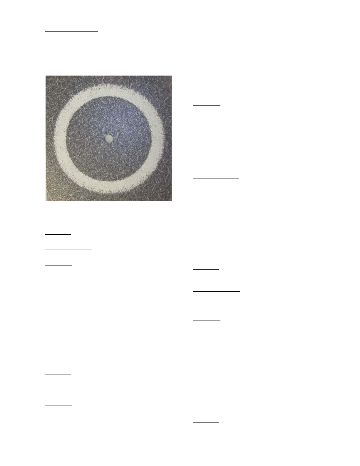
Wheels and Load: CS-0 (S-32) and S-42
sandpaper strip with 1000 gram load.
Evaluation
: Visual method, wear through of the
decorative layer.
Remark: S-42 sandpaper strips must be changed on a
frequent basis (i.e. every 200 or 500 cycles)
Figure 74
Electroplate – Chrome over Nickel
Specimen: S-16 specimen plates, plated in the
usual fashion including the chrome flash.
Wheels and Load
: CS-10 Calibrase with 500 or
1000 gram load.
Evaluation
: Visual method, by comparison of the
number of wear cycles necessary for penetration
to the nickel coating with that of a standard
specimen material tested under identical
conditions.
Remark: The color difference between the nickel and
chrome is so slight that it is necessary to prepare and use an
indicator solution that will blacken the nickel but not attack
the chrome. At intervals during the test, moisten the wear
path with the solution applied with a cotton swab on the end
of a stick. Discoloration indicates that the abrading wheels
have penetrated the chrome deposit. Clean the solution from
the specimen before resuming the test.
Electroplate – Nickel over Brass (or
Copper)
Specimen: S-16 specimen plates, plated in the
usual fashion.
Wheels and Load
1000 gram load.
Evaluation
: Visual method, by comparison of the
number of wear cycles necessary for penetration
to the brass (or copper) with that of a standard
specimen material tested under identical
conditions.
: CS-10 Calibrase with 500 or
Remark: The contrasting color of copper permits the end
point to be detected visually without an indicator solution. If a
sharper indication is desired, a formula that discolors copper
but not nickel may be used.
Electroplate – Nickel Plated Steel
Specimen: S-16 specimen plates, plated in the
usual fashion.
Wheels and Load
: CS-10 Calibrase with 500 or
1000 gram load.
Evaluation
: Visual method, by comparison of the
number of wear cycles necessary for penetration
to the steel with that of a standard specimen
material tested under identical conditions.
Remark: Use copper sulfate as an indicating solution.
Glass – Scratch Resistance
Specimen: 100 mm (4 inch) square with 6.35 mm
(0.25 inch) center hole.
Wheels and Load
Evaluation
: Comparison of the number of wear
: CS-17 with 1000 gram load.
cycles necessary to produce an equal degree of
haze or scratching with that of a standard of
similar material tested under identical conditions.
Remark 1: Reface wheels with fine side of ST-11 refacing
stone.
Remark 2: For transparent specimens, care must be taken to
mount the test specimen such that the bottom surface is not
scratched nor subjected to abrasion.
Glass – Abrasion Resistance
Specimen: 100 mm (4 inch) square with 6.35 mm
(0.25 inch) center hole. Must have a flat, even
surface and run true.
Wheels and Load
: CS-10F with 500 gram load.
Alternatively, H-18 or H-10 Calibrade wheel with
500 or 1000 gram load, which ever combination
is best suited to the desired rate of abrasion.
Evaluation
: Change in the percentage of
transmitted light and percent haze, before and
after exposure to abrasion as measured by a
hazemeter.
Remark 1: Reface wheels with fine side of ST-11 refacing
stone.
Remark 2: For transparent specimens, care must be taken to
mount the test specimen such that the bottom surface is not
scratched nor subjected to abrasion.
Remark 3: The use of an oversized nozzle is recommended
[11mm (0.4375 inch) opening vs. the nominal 8mm (0.3125
inch)].
Labels
Specimen: Affix to glass or metal specimen
plates.
35 5135 / 5155 Operating Instructions ver 1.1
Page 37
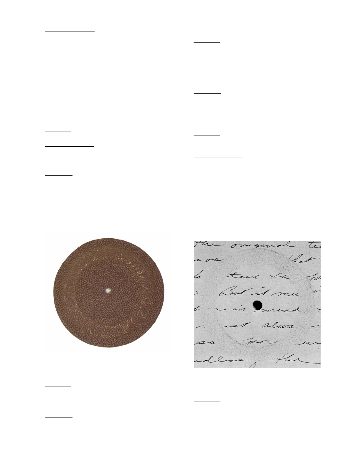
Wheels and Load: CS-10 Calibrase with 250
gram or 500 gram load.
Evaluation
: Visual changes (i.e. loss of luster;
changes of surface; etc.); weight loss method.
Remark: Duration of the test is a predetermined number of
cycles (i.e. 300, 500 or whatever number is needed to reach
the degree of wear to be regarded as the end point of the
test). The loss in milligrams is calculated on a 1000 cycle
basis which gives a Taber numerical wear index directly
comparable with that of similar materials tested under the
same conditions.
Leather Coverings – Luggage and
Upholstery (Figure 75)
Specimen: 100 mm (4 inch) diameter or square
with 6.35 mm (0.25 inch) center hole.
Wheels and Load
with 500 gram or 1000 gram load. Alternatively
use H-18 or H-22 Calibrade with 1000 gram
load.
Evaluation
: Weight loss method, visual changes
(i.e. loss of luster; changes of surface; color
changes; breakthrough of top coat).
Remark: H-22 Calibrade wheels can be used on the more
durable grades of leather subject to harsh wear; dyed,
surface colored leather may require less severe abrasion
with the CS-10 or CS-17 Calibrase wheels to produce a test
of sufficient duration to judge correctly the degree of
abrasion resistance.
: CS-10 or CS-17 Calibrase
Linoleum
Specimen: 100 mm (4 inch) diameter or square
with 6.35 mm
Wheels and Load
(0.25 inch) center hole.
: H-18 or H-22 Calibrade with
500 or 1000 gram load. For solid linoleum
subjected to extreme wear or cutting action, S35 Tungsten Carbide wheels with 1000 gram
load.
Evaluation
: Weight loss method or depth of wear
method [maximum depth of penetration
recommended is 0.8 mm
(0.0312 inch)].
Paper – Erasure Tests (Figure 76)
Specimen: 108 mm (4.25 inch) diameter with 6.35
(0.25 inch) center hole, mounted on S-36 or
mm
S-36-1 Mounting Card.
Wheels and Load
gram or 500 gram load.
Evaluation
: Visual end point determined by
partial erasure of ink marks from wear path
surface.
Remark: The properties to be determined are: 1) ease of
erasure, 2) amount of damage to surface from abrasion, 3)
ability of specimen to accept rewriting after erasure, 4)
number of times the specimen will accept erasure and
rewriting. The specimen is prepared by writing or drawing
circular lines on the surface to be tested using a permanent
ink. The ink should be thoroughly dried on the conditioned
paper before testing.
: CS-10 Calibrase with 250
Figure 75
Leather (Shoe Soles)
Specimen: 100 mm (4 inch) diameter or square
with 6.35 mm
Wheels and Load
500 gram or 1000 gram load.
Evaluation
wear method [maximum depth of penetration
recommended is 0.8 mm
36 5135 / 5155 Operating Instructions ver 1.1
(0.25 inch) center hole.
: H-18 or H-22 Calibrade with
: Weight loss method; or depth of
(0.0312 inch)].
Figure 76
Paper – Scuffing Test
Specimen: 108 mm (4.25 inch) diameter or square
with 6.35 mm
mounted on S-36 or S-36-1 Mounting Card.
Wheels and Load
with 500 or 1000 gram load. Alternately, CS-5
(0.25 inch) center hole center hole
: H-10, H-18 or H-22 Calibrade
Page 38
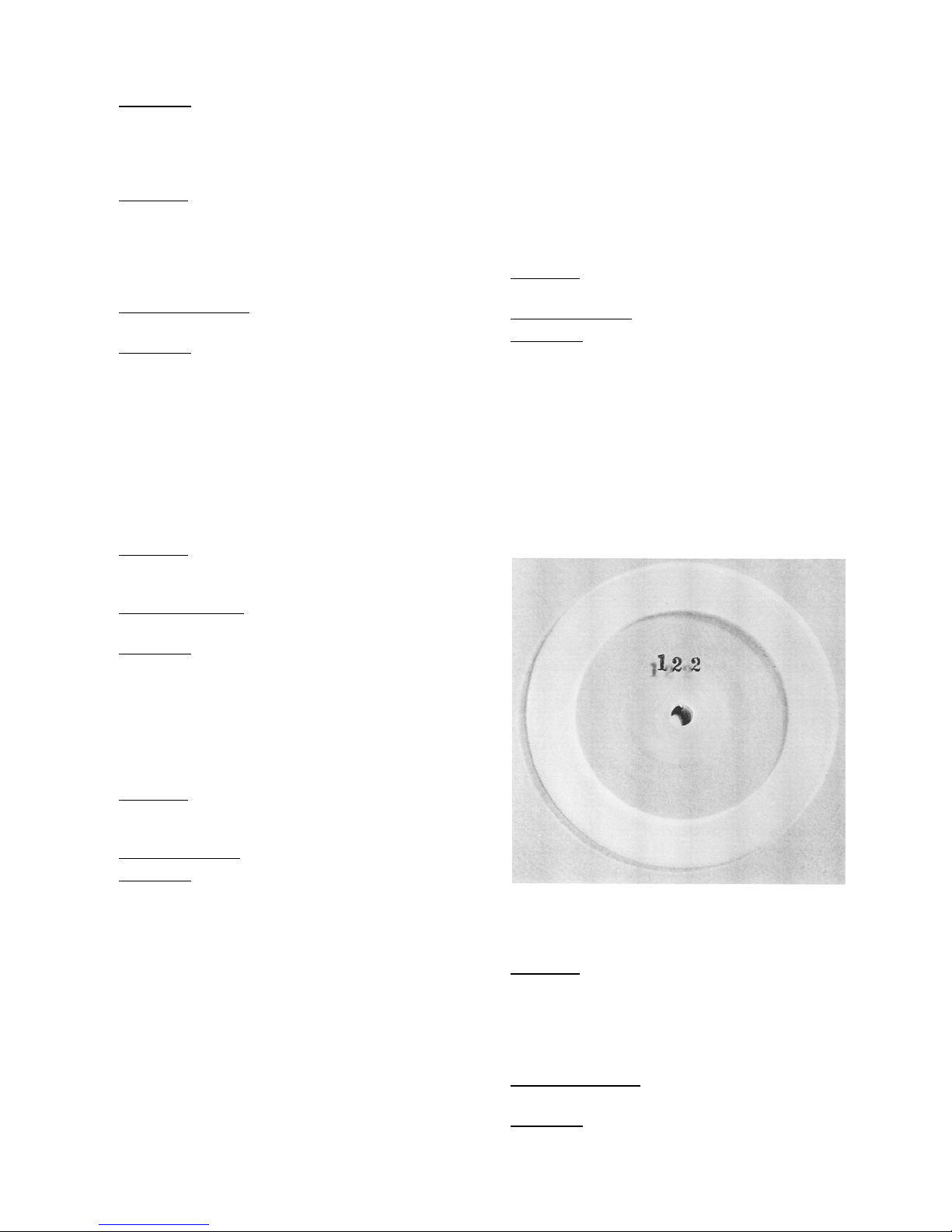
with 250 or 500 gram load.
Evaluation
: Visual change in gloss.
Paper and Cardboard – Abrasion
Resistance
Specimen: 100 mm (4 inch) diameter or square
with 6.35 mm
(0.25 inch) center hole for
sufficiently rigid materials; for flexible materials,
108 mm
mm
(4.25 inch) diameter or square with 6.35
(0.25 inch) center hole center hole mounted
on S-36 or S-36-1 Mounting Card.
Wheels and Load
: CS-10 Calibrase with 250
gram or 500 gram load.
Evaluation
: Visual changes (i.e. loss of luster;
changes of surface; etc.); weight loss method.
Remark: Duration of the test is a predetermined number of
cycles (i.e. 100, 300, 500 or whatever number is needed to
reach the degree of wear to be regarded as the end point of
the test). The loss in milligrams is calculated on a 1000 cycle
basis which gives a Taber numerical wear index directly
comparable with that of similar materials tested under the
same conditions.
Paste (Powder)
Specimen: Paste (i.e. toothpaste) or a paste
made of powder and water, applied as a thin
layer to acetate indicator plates.
Wheels and Load
250 or 500 gram load.
Evaluation: Visual method, by comparison of the
number of wear cycles necessary to produce an
equal degree of haze or scratching with that of a
standard of identical material tested under
identical conditions.
: CS-0 or S-32 Calibrase with
after firing from multiple sheets. Shearing and punching of
the plates is likely to cause some shattering of the enamel,
this is permissible if it does not extend into the path of the
wheels.
Remark 3: Special care must be taken to avoid warping the
plates in firing, since flatness of the specimen is essential to
accurate test results. Should the 20 gage S-16 specimen
plate prove too thin to withstand the heat without warping,
use heavier metal for plates.
Plastics – Transparent (Figure 77)
Specimen: 100 mm (4 inch) diameter or square
with 6.35 mm
Wheels and Load
Evaluation: Change in the percentage of
transmitted light and percent haze, before and
after exposure to abrasion as measured by a
hazemeter.
Remark 1: Reface wheels with fine side of ST-11 refacing
stone.
Remark 2: For transparent specimens, care must be taken to
mount the test specimen such that the bottom surface is not
scratched nor subjected to abrasion.
Remark 3: The use of an oversized nozzle is recommended
[11mm (0.4375 inch) opening vs. the nominal 8mm (0.3125
inch)].
(0.25 inch) center hole.
: CS-10F with 500 gram load.
Porcelain Enamel
Specimen: Prepared on S-16 or similar plate
[100 mm
center hole].
Wheels and Load
Evaluation
cycles to the first sizeable scratch as the wheels
begin to penetrate the surface glaze. Also by
comparison with a standard of the same material
tested under identical conditions. If desired, the
test may be continued to a more advanced end
point than the first sizeable scratch.
Remark 1: The hardness and density of porcelain enamel
makes them highly resistant to abrasion and scratching.
Because of the similarity of porcelain glaze with glass, the
abrading action of the Calibrase wheels is barely noticeable
in the early stages of the test although material is being
slowly removed. After a time, however, the wheels begin to
abrade through the surface glaze and penetrate the coarse
substrate.
Remark 2: Porcelain enamel frit may be sprayed on S-16
plates for testing or specimens may be cut either before or
37 5135 / 5155 Operating Instructions ver 1.1
(4 inch) square with 6.35 mm (0.25 inch)
: CS-17 with 1000 gram load.
: Visual method, based on number of
Figure 77
Plastics – Opaque
Specimen: 100 mm (4 inch) diameter or square
(molded, sheared, or sawed) with 6.35 mm
inch)
center hole for material to 6.35 mm (0.25 inch)
thick; 9.525 mm
extension nut for material 6.35 mm
12.7 mm
(0.5 inch) thick..
Wheels and Load
with 1000 gram load.
Evaluation
Remark: The CS-17 Calibrase wheel under 1000 grams
: Weight loss method.
(0.375 inch) hole for S-21
(0.25 inch) to
: CS-17 or CS-10 Calibrase
(0.25
Page 39
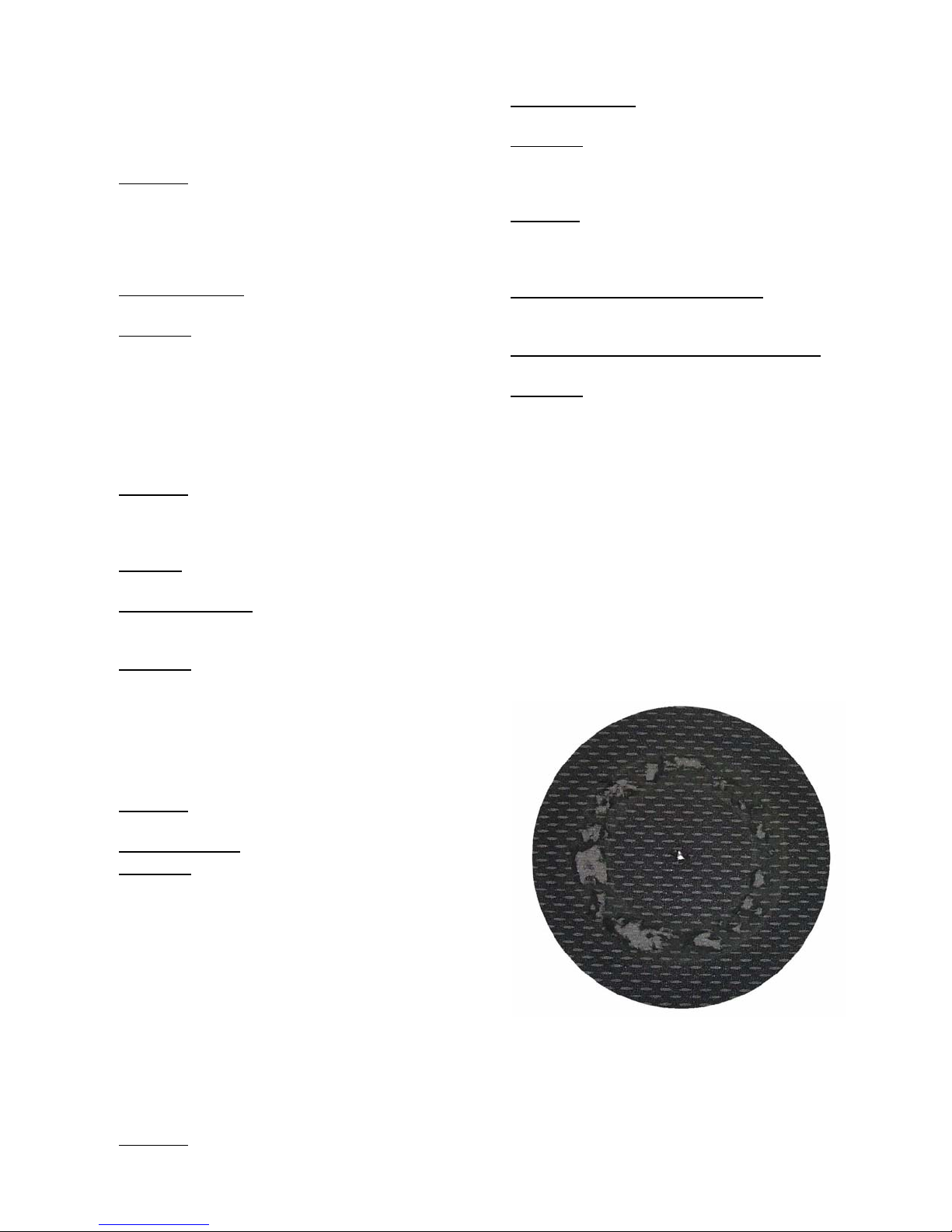
pressure is ordinarily used but the CS-10 may be substituted
when it is desired to extend the duration of the test for low
abrasion resistance finishes.
Rubber – Test A
with 6.35 mm
Wheels and Load
(0.25 inch) center hole.
: H-10 or H-18 Calibrade with
500 or 1000 gram load.
Evaluation
: Weight loss method.
Specimen: 100 mm (4 inch) diameter or square
for sufficiently thick and rigid materials; for thin,
flexible materials, 100 mm
adhered to S-36 mounting card or 108 mm
diameter when adhered to S-36-1 mounting
inch)
(4 inch) square when
(4.25
card.
Wheels and Load
: H-18 or H-22 Calibrade with
1000 gram load.
Evaluation
: Weight loss or depth of wear
method.
Remark: Flat sheet rubber samples subjected to unusually
severe abrading and cutting action in actual service may be
tested with the S-35 tungsten carbide wheels with 1000
gram load.
Rubber – Test B
Specimen: Wheels, molded or cut from sheet in
place of flat specimen; size: 50 mm
diameter x 12.7 mm
15.875mm
Abradant
(0.625 inch) center hole.
: ST-11 stone mounted on standard
(0.5 inch) thick with
specimen holder.
Wheels and Load
: Molded wheel specimens
mounted on abrading wheel shafts with 1000g
load.
Evaluation
Remark: When testing specimens molded and mounted as
wheels with the ST-11 stone, it should be noted that the
stone has a coarse and fine side; the side used should be
specified in the test report.
: Weight loss method.
(2 inch)
Textiles (Figures 78 & 79)
Specimen: 133 mm (5.25 inch) round with 12.7
mm
(0.25 inch) center hole, 108 mm (4.25 inch)
diameter with 6.35 mm
when mounted to S-36-1 Mounting Card.
Wheels and Load – Delicate Fabrics
Calibrade or CS-10 Calibrase with 500 gram or
250 gram load.
Wheels and Load – Medium / Heavy Fabrics
18 or H-22 Calibrade with 1000 gram load.
Evaluation
: Visual method, changes in luster;
surface; color; appearance of first broken
threads; appearance of a hole. Alternatively,
physical changes such as thickness; air
permeability; weight; strength.
Remark 1: Prepare center hole by folding a 133 mm (5.25
inch) round or square sample twice and cutting off the folded
corner to produce a small central hole for the clamp screw.
Mount the specimen on the holder and clamp tightly with
clamp plate and nut. Adjust the clamp ring to a tight fit over
the specimen and holder and draw taut by pressing the
clamp ring over the edge of the holder. When the desired
tension is obtained, tighten the clamp ring adjusting screw.
Avoid tightening to excess so as not to buckle the fabric.
Remark 2: Use of mounting cards prevents stretch and
wrinkles.
Remark 3: Vacuum control should be set to prevent
abradings from being trapped in the threads.
(0.25 inch) center hole
: H-38 (fine)
: H-
Safety Glazing Materials
Specimen: 100 mm (4 inch) square with 6.35 mm
(0.25 inch) center hole.
Wheels and Load: CS-10F with 500 gram load.
Evaluation
: Change in the percentage of
transmitted light and percent haze, before and
after exposure to abrasion as measured by a
hazemeter.
Remark 1: Reface wheels with fine side of ST-11 refacing
stone.
Remark 2: For transparent specimens, care must be taken to
mount the test specimen such that the bottom surface is not
scratched nor subjected to abrasion.
Remark 3: The use of an oversized nozzle is recommended
[11mm (0.4375 inch) opening vs. the nominal 8mm (0.3125
inch)].
Steel
Specimen: 100 mm (4 inch) square or diameter
38 5135 / 5155 Operating Instructions ver 1.1
Figure 78
Page 40
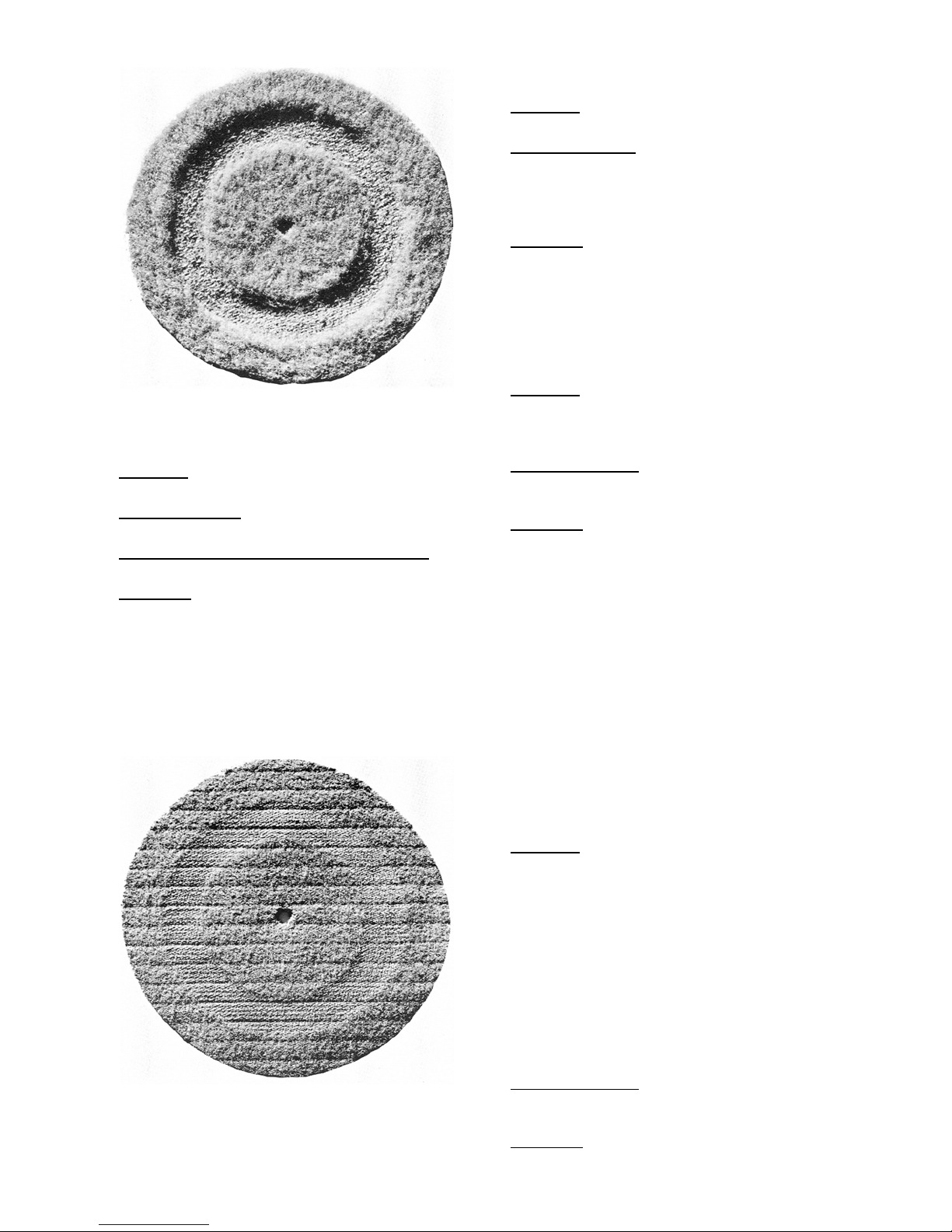
Tile (Rubber and Asphalt)
Specimen: 100 mm (4 inch) diameter or square
with 6.35 mm
Wheels and Load
(0.25 inch) center hole.
: H-18 or H-22 Calibrade with
500 or 1000 gram load. For solid linoleum
subjected to extreme wear or cutting action, S35 Tungsten Carbide wheels with 1000 gram
load.
Evaluation
: Weight loss or depth of penetration
[maximum depth of penetration recommended is
0.8 mm
Remark: For specimens 6.35 mm (0.25 inch) to 12.7 mm
(0.5 inch) thick, use S-21 Extension Nut.
(0.0312 inch)].
Wax Coating
Figure 79
Textiles – Upholstery (Figure 80)
Specimen: 108 mm (4.5 inch) round or square
mounted on S-36 mounting card.
Wheels and Load
with 500 or 1000 gram load.
Wheels and Load – Medium / Heavy Fabrics
18 or H-22 Calibrade with 1000 gram load.
Evaluation
: Visual method, changes in luster;
surface; color; appearance of first broken
threads; appearance of a hole. Alternatively,
physical changes such as thickness; air
permeability; weight; strength.
Remark: Upholstery materials ordinarily require the H-38
Calibrade wheel with 500 gram load; floor coverings, such as
broadloom carpets or automobile floor mats should be tested
with 1000 gram load using H-18 or sometimes H-22 wheels.
: H-38, H-18 or H-22 Calibrade
: H-
Specimen: Coating applied to substrate
approximately 100 mm
(4 inch) square with 6.35
mm (0.25 inch) center hole (i.e. S-16 specimen
plate).
Wheels and Load
: CS-17 Calibrase with 1000
gram load. Alternatively, the H-22 or H-18
Calibrade with 1000 gram load may be used.
Evaluation
: Visual method, by comparison of the
number of wear cycles necessary to produce an
equal degree of abrasion with that of an
unwaxed standard of like material tested under
otherwise identical conditions.
Remark 1: In making the test, it is necessary to allow for the
fact that the wheels will become coated with wax transferred
from the specimen. Depending on the number of test cycles,
wheels may require refacing during testing.
Remark 2: A coating of wax applied to a surface has
practically no abrasion resistance of itself but does act as a
lubricant which reduces the tendency of two surfaces
rubbing together to abrade. This lubricating effect prolongs
the life of the finish to varying degrees, and the action of the
wax is similar to that of grease in lubricating mechanical
devices.
Wire – Insulated (Figure 81)
Figure 80
39 5135 / 5155 Operating Instructions ver 1.1
Specimen: To prepare the specimen, an S-36-1
mounting card is placed on the specimen holder.
An abrading wheel cap nut is placed temporarily
over the holder center screw to act as a guide.
The specimen wire is wound in a clockwise
direction, in a flat spiral, outward from the
circumference of the guide to the edge of the
holder. The cap nut guide is then removed and
the coiled wire specimen, mounted on its holder,
is placed against a flat surface and weighted
with 5 pounds for 1 hour. The specimen holder
clamp plate and clamp ring are attached to the
holder before the test begins.
Wheels and Load
: CS-17 Calibrase with 1000
gram load. Alternatively use H-22 Calibrade
with 1000 gram load.
Evaluation
: Visual end point, at the first sign that
Page 41
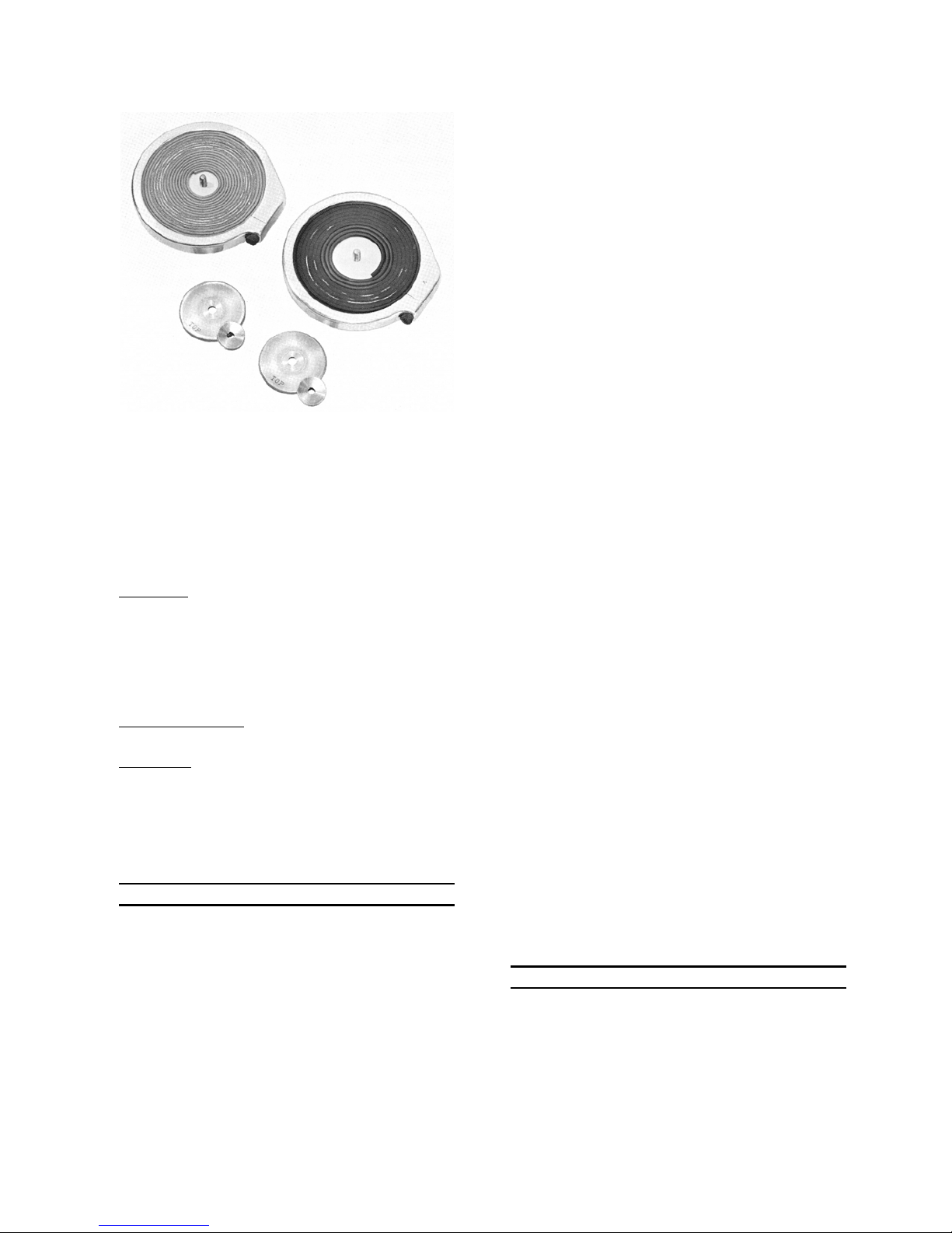
the wheels have worn through the insulation to
the wire.
dimensions of the fibers; the structure of the
yarns; the construction of the fabrics; and the
type, kind, and amount of finishing material
added to the fibers, yarns or fabrics. For rigid
materials, material surface roughness should be
considered.
The effect of age may impact the abrasion
resistance of organic materials and coatings.
Many coatings show low abrasion the first few
days but progressively improve during the
following 30 days as the coating cures.
The type of abradant used also plays an
important role. All abrasion tests are subject to
variation due to changes in the abradant during
specific tests. To minimize this variation, the
abradant must be cleaned at frequent intervals
and checked periodically.
Figure 81
Remark: Use of an electrical current to detect the end point
automatically, is suggested. One end of the specimen wire
may be grounded and a soft wire tinsel brush, in contact with
the wear path, conducted to a suitable electronic switch to
stop the abraser at a predetermined end point corresponding
to the breakdown of the insulation.
Wood
Specimen: 100 mm (4 inch) square with 6.35 mm
(0.25 inch) center hole for materials to 6.35 mm
(0.25 inch) thick. Alternatively, drill a 4.76 mm
(0.1875 inch) hole and thread the specimen onto
the center screw of the specimen holder. For
specimens 6.35 mm
inch)
thick, use the S-21 Extension Nut.
Wheels and Load
(0.25 inch) to 12.7 mm (0.5
: H-18 or H-22 Calibrade with
500 gram or 1000 gram load.
Evaluation: Weight loss or depth of wear method
Remark 1: The effect of moisture on the wear factor of wood,
such as decking, can be determined by soaking the wood in
water for a specified length of time and testing in that
condition using the rimmed specimen holder (E140-75).
INFLUENCES ON RESULTS
The measurement of abrasion resistance is a
complex phenomenon and may be influenced by
a number of factors. If there are significant
differences between reported test results for two
laboratories (or more), it is often attributed to
procedural errors, an instrument that is out of
calibration or one of the factors mentioned
below.
The resistance to abrasion is greatly affected by
the characteristics of the material itself. For
example, textile materials are affected by the
inherent mechanical properties of the fibers; the
Other factors to consider include the conditions
of the tests (i.e. temperature and humidity,
conditioning of specimens, etc.), and test
methodology (i.e. vacuum nozzle height,
pressure between the specimen and abradant,
etc.). For comparable and reproducible tests, it
is recommended that all testing be performed
under conditions covered by an established test
procedure.
The measurement of the relative amount of
abrasion may also be affected by the method of
evaluation. This is especially true with visual
assessments, as the results may be influenced
by the judgment of the operator.
If a thorough investigation does not uncover the
cause for the difference, comparative tests
should be performed to determine if there is a
statistical bias between the laboratories. The
test samples used must be as homogeneous as
possible, drawn from the material from which the
disparate test results were obtained, and
randomly assigned in equal numbers to each
laboratory for testing. The test results from the
laboratories should be compared using a
statistical test for unpaired data, at a probability
level chosen prior to the testing series. If bias is
found, either its cause must be found and
corrected, or future test results must be adjusted
in consideration of the known bias.
MAINTENANCE
The Rotary Platform Abrasion Tester is a
precision instrument that, if used and maintained
properly, should give you many years of troublefree service. This section will provide a general
guideline in caring for your instrument.
40 5135 / 5155 Operating Instructions ver 1.1
Page 42
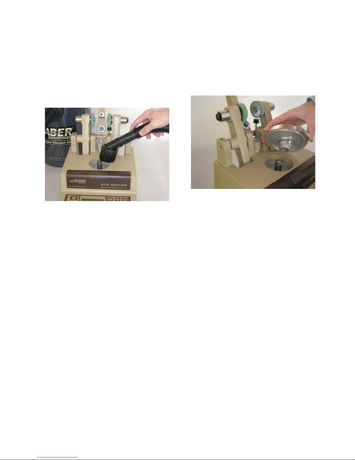
General Care
As with any precision test instrument, basic
common sense care will ensure a long life from
your Rotary Platform Abrasion Tester. Brush or
vacuum all particulate material and debris off the
instrument and surrounding work area. The
motor drive shaft cavity is prone to collect
debris. Periodically, remove the specimen
holder and vacuum this area using the suction
brush attached to the vacuum hose or Taber
Clean Up Hose.
be used or to clean the motor cavity.
Each specimen table is designed with a drive pin
and ball plunger to provide a positive retaining
force that locks the specimen holder in place.
To remove the holder, place your fingers under
the edge of the holder and lift straight upward.
In the event that the holder cannot be removed,
DO NOT USE a tool to pry the table up. Contact
Taber Industries for further instructions.
Figure 83
Figure 82
Keep the vertical drive shaft of the Abraser and
the shaft holes of the specimen holders wiped
clean with a soft cloth. Drive shaft and holder
bores are machined to close tolerances. Never
force on a holder when dirt is present. This may
damage the holder bore and affect its accuracy,
or make it impossible to remove the holder
without damaging the motor.
DO NOT allow any foreign particulate to get
into any of the bearing assemblies.
DO NOT spill any liquids onto or into the
instrument or onto any of the bearing
assemblies. Wipe off all spills immediately.
DO NOT operate the Rotary Platform
Abrasion Tester at freezing, sub-zero or
elevated, high temperatures. The
instrument is designed to operate in a
temperature range at or around room
temperature and in nominal room humidity.
Lubrication
The bearing assemblies are factory lubricated
and do not require regular lubrication.
Installing / Removing the Specimen
Holder
With frequent specimen holder removal, the ball
plunger may need to be adjusted. Using a
screwdriver, tighten the ball plunger
approximately 1/16 turn. A silicone type spray
may be used to lubricate.
To install the specimen holder, align the bottom
opening with the vertical drive shaft of the
Abraser motor making sure that the ball plunger
and drive pin are aligned. Using a downward
force, press lightly on the specimen table until it
is fully seated.
Cleaning Vacuum Pick-Up Nozzle
Abraded material and debris may collect in the
vacuum pick-up nozzle orifices. Keep the
orifices clean of particulate by using a small
brush.
Replacing Quick Release Wheel Collet
The expandable collet for the Quick Release
Wheel Hub is manufactured out of a wear
resistant plastic, however it should be replaced
when the retaining lip shows signs of wear. An
indication of this wear is a rounding of the lip or
wheels are no longer held securely in place. To
facilitate this repair, a replacement collet kit is
available from Taber Industries.
The specimen holder can be removed from the
instrument. This will allow for optional holders to
41 5135 / 5155 Operating Instructions ver 1.1
Page 43
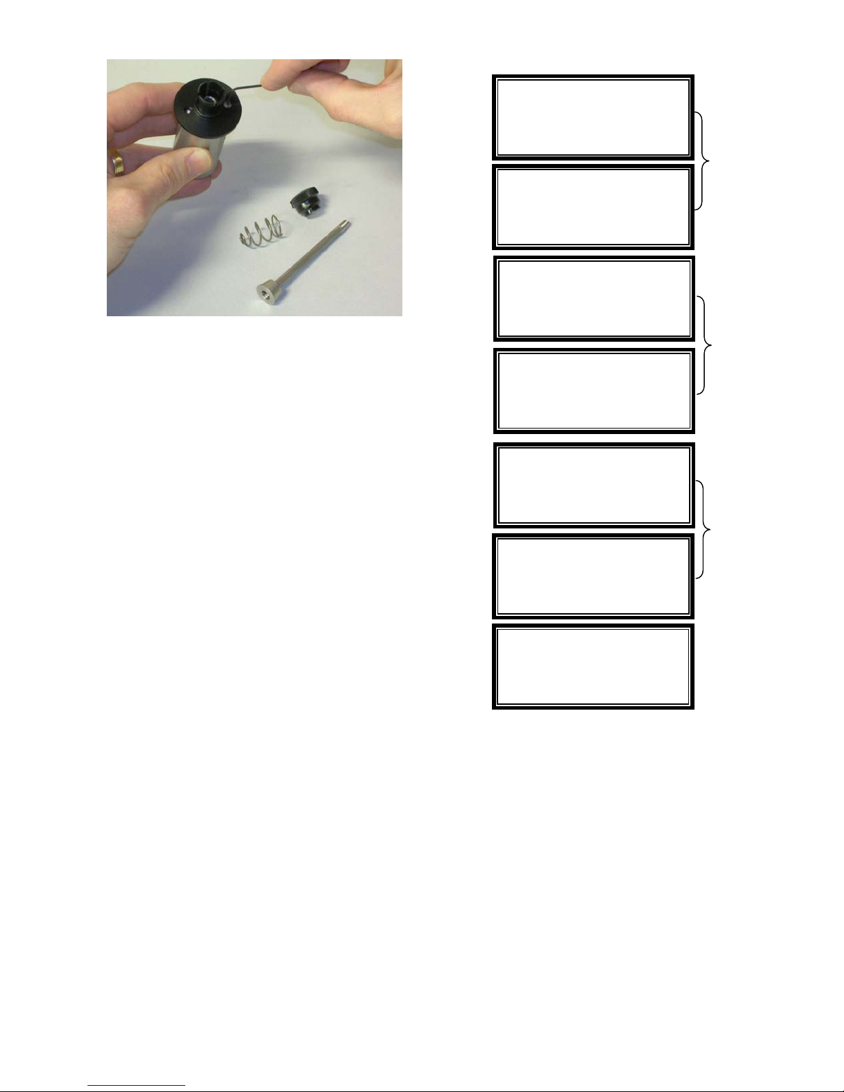
1-Speed 4-Vacuum
2-Refacing 5-Outlet
3-Display 6-Reset
>Select Menu Option
1-Speed 4-Vacuum
2-Refacing 5-Outlet
3-Display 6-Reset
>0 Zero key for more
Alternating
Display
Screens
Figure 84
Vacuum Unit
The vacuum unit included with model 5135 and
5155 is designed with a heavy-duty motor that
includes life-lubricated sealed bearings.
Vacuum cartridge filter and collection bags
should be replaced on a regular basis.
Motor Calibration
The motor speed is checked and adjusted every
time the proximity switch is triggered. The CPU
compares the amount of time that the last
revolution took to the expected amount of time,
based on the cycles per minute setting. The
voltage sent to the motor controller is then
adjusted to accommodate any deviation in the
expected versus actual revolution time. This
feature should be factory calibrated on an
annual basis.
Clock
A menu option provides a means to change the
time and date for the internal clock. The
following explains how to access this function:
1. Press the MENU button to display Menu
Options (see below for screen displays).
2. From the menu options, press 0 key for
more selections then 1 to select Clock.
3. The display screen will prompt you to type
the required time and date information.
For time, enter hour and minutes
(HH:MM); for date, enter month, day and
year (MM/DD/YY).
4. Press ENTER to save or CLEAR to
cancel.
1-Clock
2-Usage
>Select Menu Option
1-Clock
2-Usage
>CLEAR key to return
Alternating
Display
Screens
Usage
Through the Menu Option, you can also display
the total cycles of operation that the instrument
has worked. To view:
1. Press the MENU button to display Menu
2. From the menu options, press 0 key for
3. Press CLEAR, to return to the menu
Change Time and Date
00:00 HH:MM
00/00/00 MM/DD/YY
>ENTER hours (00-23)
Change Time and Date
00:00 HH:MM
00/00/00 MM/DD/YY
>CLEAR key to return
Time/Date set to
XX:XX HH:MM
XX/XX/XX MM/DD/YY
Options (see below for screen displays).
more selections then 2 to select Usage.
screen.
Alternating
Display
Screens
42 5135 / 5155 Operating Instructions ver 1.1
Page 44
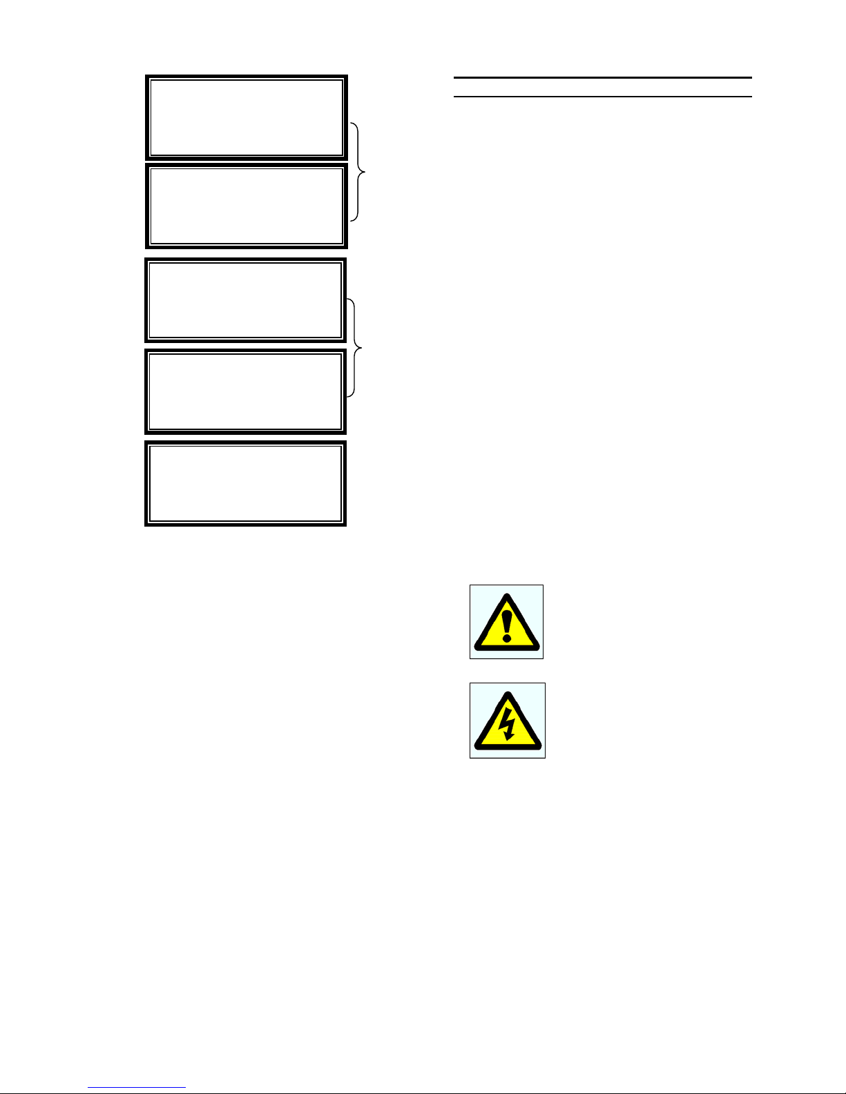
1-Speed 4-Vacuum
2-Refacing 5-Outlet
3-Display 6-Reset
>Select Menu Option
1-Speed 4-Vacuum
2-Refacing 5-Outlet
3-Display 6-Reset
>0 Zero key for more
1-Clock
2-Usage
>Select Menu Option
1-Clock
2-Usage
>CLEAR key to return
Alternating
Display
Screens
Alternating
Display
Screens
Total cycles: XXXXXX
>CLEAR key to return
CALIBRATION / FACTORY SERVICE
Taber Industries recommends that you calibrate
the Rotary Platform Abrasion Tester on an
annual basis. The software includes a
calibration reminder, which is triggered one year
after the initial date of calibration.
Should your Rotary Platform Abrasion Tester
require calibration, repair, or adjustment,
carefully pack it in a rugged container with
adequate cushioning material. After obtaining a
return authorization number from the factory, the
unit should be shipped, transportation charges
prepaid, to Taber Industries.
TABER® Industries
455 Bryant Street
North Tonawanda, New York 14120
USA
CAUTION – Read Instructions
Before Operating
CAUTION – Risk of Shock
43 5135 / 5155 Operating Instructions ver 1.1
Page 45
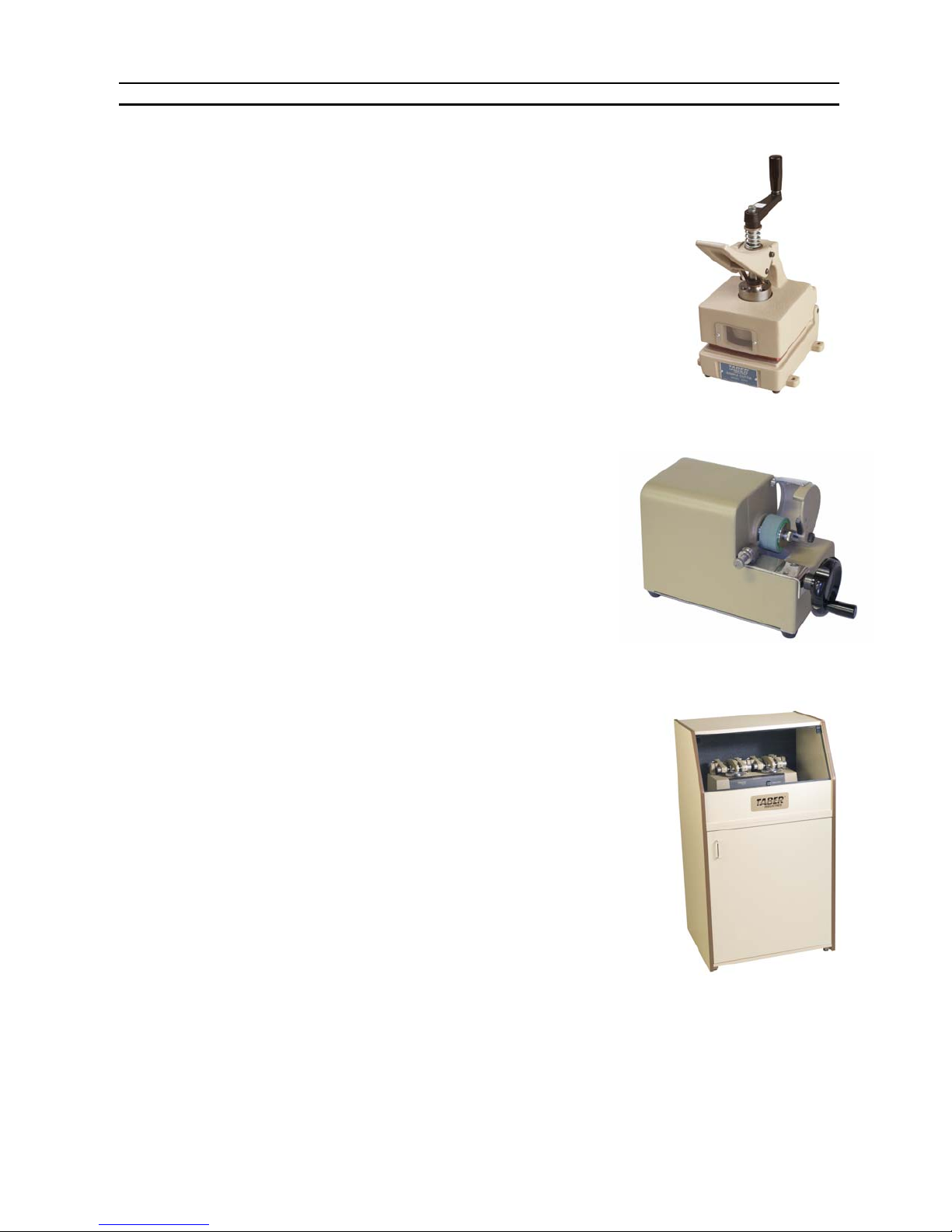
OPTIONAL ACCESSORY INSTRUMENTS
Sample Cutter 5000
The Model 5000 Sample Cutter is available to prepare a wide range of
flexible materials for testing on the Taber Rotary Platform Abraser.
Examples include: paper, cardboard, rubber, leather, vinyl, carpet, textiles,
metal foils, and flexible plastics.
This bench top instrument is designed to cut an exact 108 mm
diameter specimen and punch a 6.35 mm
tail’ rear support prevents tipping during operation, thereby eliminating the
need to secure the instrument to a work surface. A shielded punch shaft
and knife retraction system protects the operator from the cutting tools.
The punch lever is ergonomically designed to evenly transfer force through
the spring-loaded punch.
(0.25 inch) center hole. A ‘dove-
(4.2 inch)
Wheel Refacer 250
The Model 250 Wheel Refacer has been specially designed to
precision dress the working surfaces of Genuine Taber Calibrade
abrading wheels for the Taber Abraser. This compact instrument can
also be used to true out of round wheels and to correct ‘crowning’
conditions on both Calibrase and Calibrade wheels.
A refacing diamond tool is mounted in an adjustable holder, which is
supported on a shielded traverse slide. Abrading wheels are mounted
on a flanged extension of the motor shaft and are enclosed by a
hinged cover for safety during the refacing operation. By moving the
diamond point tool across the wheel faces, the wheel surfaces can be
refreshed! During operation, the vacuum unit hose is disconnected
from the Abraser and inserted in the Wheel Refacer to draw off the
abrasive cuttings. Note: To ensure identical diameters, wheels are
always refaced in pairs.
Quiet Cabinet
The Quiet Cabinet can significantly reduce the sound levels associated
with running a Taber test. Additionally, it provides a convenient, dust-free
workspace for the instrument. The typical sound level of the Taber
Abraser and its vacuum system can reach 78dB. Utilizing sound
deadening materials, the Quiet Cabinet reduces this noise level up to
20% resulting in a level that is comparable to a standard office
environment.
The upper cabinet features a hinged Plexiglas™ viewing window to
monitor testing while a detachable front permits easy transfer of the
Abraser into or out of the cabinet. The lower cabinet holds the vacuum
unit and includes a built-in exhaust system (either 120V, 60Hz or 230V,
50Hz) to provide proper air circulation. Constructed of solid wood, the
cabinet includes a high-pressure laminate outer shell for added durability.
The Quiet Cabinet is available as a complete unit, or the top and bottom
may be purchased separately.
44 5135 / 5155 Operating Instructions ver 1.1
Page 46
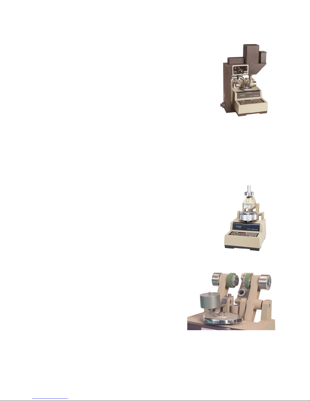
Grit Feeder Attachment 155 / 255
The Model 155 or 255 Grit Feeder is used in conjunction with the Taber
Abraser to evaluate three-body abrasion caused by the destructive action
of fine, hard particles. Positioned over the Taber Abraser, the Grit Feeder
is a freestanding instrument that deposits abrasive grit particles uniformly
and continuously onto the specimen surface. As the specimen holder
rotates, the loose grit passes under a pair of leather-clad wheels. The
resulting rolling action of the particles serves as the abradant and
contributes to the physical breakdown of the material. The vacuum hose
from the Taber Abraser is inserted into the base of the Grit Feeder allowing
a pickup tube to be positioned such that grit particles and debris are
removed. The operation of the grit feeder is controlled through the Taber
Abraser, ensuring that the turntable, grit distribution and vacuum suction
are actuated at the same time.
Two versions of the Grit Feeder are available, Model 155 and 255. Model
155 offers a hopper capacity of 1,300 grams and utilizes and alignment guide screw to set the position of
the instrument. Grit distribution and vacuum removal nozzle heights are adjusted using a thumbscrew.
Model 255 offers an increased hopper capacity of 4,500 grams. A telescoping feature allows precise
height adjustments and permits testing of specimens up to 50 mm
(2 inch). An alignment block is
incorporated into the base to assist with proper set-up. In addition, the Model 255 may be mounted to
either the right or left hand side of the Abraser, enabling two instruments to be used with Taber’s Dual
Rotary Abraser.
Multi-Media Abraser 5500
The Model 5500 Multi-Media Attachment is an accessory attachment for the
Rotary Platform Abraser used to evaluate particle abrasivity. Applications
include fluids, powders and semi-solids such as paints, pigments, adhesives,
sealants, epoxies, detergents and industrial additives. This option enables
the user to recreate actual wear conditions for contact surfaces in application
equipment, and is useful in predicting maintenance schedules.
The test medium to be evaluated is placed in a testing dish. As the dish is
rotated, a holder with three precision brass pins affixed to it rotates in the
opposite direction on a stainless steel wear disc. As the test medium flows
against the brass pins, abrasion occurs resulting in a change in weight. With
interchangeable gearing, the speed of rotation for the pin holder can be
changed which permits the testing of different material viscosity.
Scuffing Head Attachment
The Scuffing Head Attachment is used to evaluate damage
caused by the scraping action of a special scuffing head. Used
on materials such as vinyl, leather, textiles, non-woven
materials, plastics and painted products; two different weights
and three scuffing head configurations are available. Scuffing
head type “A” is similar to the flat blade of a screwdriver [blade
is approximately 8 mm
edge [blade is approximately 4 mm
“C” has a radius edge [blade is approximately 8 mm
wide].
(0.31 inch) wide]. Type “B” has a knife
(0.157 inch) wide], and type
(0.31 inch)
Used in place of the abrasive wheels, the Scuffing Head Attachment is mounted on the inside riser mount
for the left abraser arm. The abraser is operated in the normal fashion, however the vacuum system is
not utilized. With a hinged design, the scuffing tool may be raised when not in use.
45 5135 / 5155 Operating Instructions ver 1.1
Page 47

Haze Kit
The Haze Kit is intended for those customers who perform abrasion testing on plastics or glass. This kit
includes a modified vacuum pick-up nozzle with 11mm
(0.3125 inch) openings. Also supplied are a 0.8 mm (0.0132 inch) gage pin for setting the gap between
8mm
(0.4375 inch) orifice openings versus the nominal
the specimen and vacuum nozzle and an antistatic brush for cleaning the specimen.
Arm Height Extension Kit
The Arm Height Extension Kit was engineered to accommodate specimens that exceed the
recommended thickness [up to 40mm (1.5 inch)]. This kit raises the position of the abrader arms and
allows for the correct alignment and positioning of the abrasive wheels. An extension post is threaded to
the turntable and by using the appropriate combination of turntable shims the proper arm position relative
to the specimen. Kits are available for Single and Dual abrasers and include the arm height extenders,
turntable adaptor and a set of 6 shims.
calibration.
It is necessary to return your instrument to Taber Industries for
Calibration Verification Kit
Instrument verification can be performed using the Calibration Verification Kit. This cost effective method
enables the operator to verify if an instrument is in calibration or if it is in need of repair. Procedures
described in the kit allow the verification of proper abraser arm alignment (longitudinal and transverse
alignment), wheel tracking and wear pattern, irregular bearing integrity and vacuum suction force. Other
inspections include vacuum pick-up nozzle wear, table flatness, turntable speed and accessory weights.
This kit is NOT intended as a substitution for regular instrument calibration.
46 5135 / 5155 Operating Instructions ver 1.1
Page 48
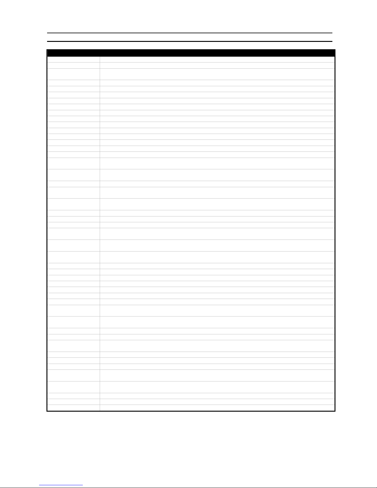
TEST METHOD REFERENCES
Reference Title
ANSI INCITS 322 Card Durability Test Methods
ANSI/SAE Z26.1 Safety Glazing Materials for Glazing Motor Vehicles and Motor Vehicle Equipment
ASTM C1353
ASTM C501 Standard Test Method for Relative Resistance to Wear of Unglazed Ceramic Tile by the Taber Abraser
ASTM D1044 Standard Test Method for Resistance of Transparent Plastics to Surface Abrasion
ASTM D3389 Standard Test Method for Coated Fabrics Abrasion Resistance (Rotary Platform Double- Head Abrader)
ASTM D3451 Standard Practices for Testing Polymeric Powders and Powder Coatings
ASTM D3730 Standard Guide for Testing High-Performance Interior Architectural Wall Coatings
ASTM D3884 Standard Guide for Abrasion Resistance of Textile Fabrics (Rotary Platform, Double-Head Method)
ASTM D4060 Standard Test Method for Abrasion Resistance of Organic Coatings by the Taber Abraser
ASTM D4685 Standard Test Method for Pile Retention of Corduroy Fabrics
ASTM D4712 Standard Guide for Testing Industrial Water-Reducible Coatings
ASTM D5144 Standard Guide for Use of Protective Coating Standards in Nuclear Power Plants
ASTM D5146 Standard Guide to Testing Solvent-Borne Architectural Coatings
ASTM D5324 Standard Guide for Testing Water-Borne Architectural Coatings
ASTM D6037 Standard Test Methods for Dry Abrasion Mar Resistance of High Gloss Coatings
ASTM F1478
ASTM F1978
ASTM F362 Standard Test Method for Determining the Erasability of Inked Ribbons
ASTM F510
EN 438-2
EN 660-2 Resilient floor coverings - Determination of wear resistance - Part 2: Frick-Taber Test
EN 13329 Laminate floor Coverings - Specifications, Requirements and Test Methods
EN 13696 Wood and Parquet Flooring - Determination of Elasticity and Resistance to Wear
Fed. Specification
TT-P-0091D
Fed. Test Method
GG-P-455b
Fed. Test Method
191A, 5306.1
ISO 10074 Specifications for Hard Anodic Oxidation Coatings on Aluminum and its Alloys
ISO 3537 Road Vehicles - Safety Glazing Materials - Mechanical Tests
ISO 4586-2 High-pressure decorative laminates - Sheets made from thermosetting resins
ISO 5470-1 Rubber or Plastics Coated Fabrics - Determination of Abrasion Resistance
ISO 7784-1 & -2 Paints and Varnishes; Determination of Resistance to Abrasion
ISO 9352 Plastics; Determination of Resistance to Wear by Abrasive Wheels
MIL-A-8625F(1) Military Specification - Anodic Coatings for Aluminum and Aluminum Alloys
MIL-C-22992E
MIL-P 18493
(NAVY)
MIL-PRF-61002A Military Specification - Pressure-Sensitive Adhesive Labels for Bar Coding
MIL-STD-13231 Department of Defense Standard Practice - Marking of Electronic Items
MIL-T-28800E
NALFA LF-01 Laminate Flooring
NEMA LD3 High Pressure Decorative Laminates
SAE J 365 Method of Testing Resistance to Scuffing of Trim Materials
SAE J 948
SAE J 1530
SAE J 1847 Abrasion Resistance Testing - Vehicle Exterior Graphics and Pin Striping
Tappi T 476 Abrasion Loss of Paper and Paperboard (Taber-type method)
UN – ECE Reg. 43 Uniform Provisions Concerning the Approval of Safety Glazing and Glazing Material
Standard Test Method Using the Taber Abraser for Abrasion Resistance of Dimension Stone Subjected
to Foot Traffic
Standard Test Method for Determination of Abrasion Resistance of Images Produced from Copiers and
Printers (Taber Method)
Standard Test Method for Measuring Abrasion Resistance of Metallic Thermal Spray Coatings by Using
the Taber Abraser
Standard Test Method for Resistance to Abrasion of Resilient Floor Coverings Using an Abrader with a
Grit Feed Method
Decorative High Pressure Laminates (HPL); Sheets Based on Thermosetting Resins; Part 2:
Determination of Properties
Interim Federal Specification - Paint, Rubber Base, Styrene-Butadiene Type, Interior, for concrete floors.
Plates and Foils, Photographic (Photosensitive Anodized Aluminum)
Abrasion Resistance of Cloth: Rotary Platform, Double-Head (Taber) Method
General Specification for Connectors, Plugs and Receptacles, Electrical Waterproof, Quick Disconnect,
Heavy Duty Type
Military Specification - Packing, Performed, Carbon; and Carbon Stock, Packing
Military Specification - General Specification for Test Equipment for use with Electrical and Electronic
Equipment
Test Method for Determining Resistance to Abrasion of Automotive Bodycloth, Vinyl, and Leather, and
the Snagging of Automotive Bodycloth
Test Method for Determining Resistance to Fiber Loss, Resistance to Abrasion and Bearding of
Automotive Carpet Materials
47 5135 / 5155 Operating Instructions ver 1.1
Page 49
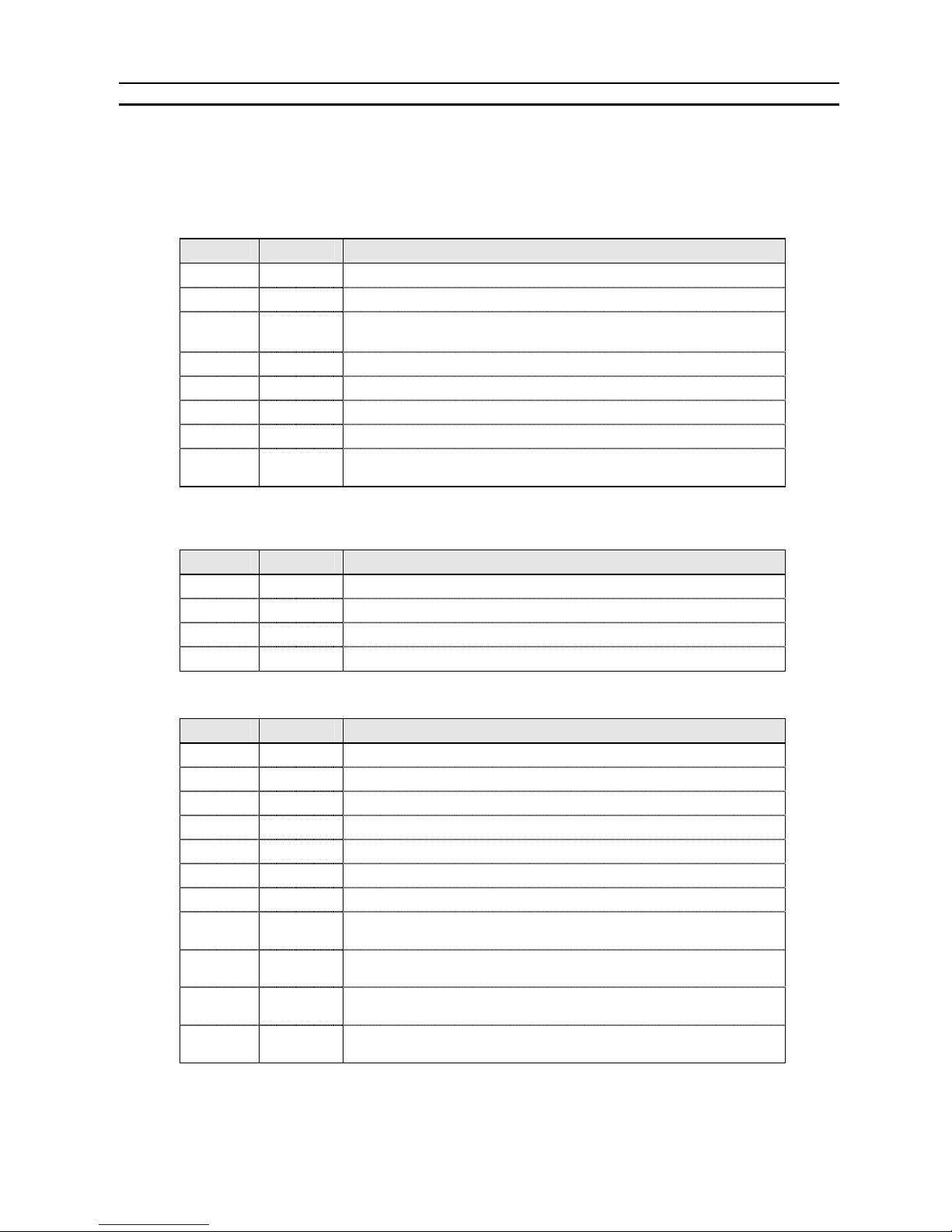
CONSUMABLES / ACCESSORIES
Genuine Taber Wheel Sets (sold in pairs)
®
Calibrase
Generally used for testing rigid specimens.
Part No. Model Description
132030
132150-1
125321 CS-10F Calibrase Wheel Set (resilient) – brown [fine abrasive]
125320 CS-10 Calibrase Wheel Set (resilient) – green [medium abrasive]
132684 CS-10P Calibrase Wheel Set (resilient) – green [medium abrasive]
130950 CS-10W Calibrase Wheel Set (resilient) – white [medium abrasive]
125322 CS-17 Calibrase Wheel Set (resilient) – green [coarse abrasive]
132661 CS-T3 Calibrase Wheel Set (resilient) – red [fine abrasive], {was Type III
– Resilient wheel composed of rubber and aluminum oxide abrasive particles.
S-45 Wheel Tracking Cards, pkg. 15
Rotary Abraser Calibration Verification Kit
NOTE: Reface with ST-11 refacing stone
improved CS-10F wheel}
Calibrade
particles. Generally used for testing flexible specimens.
®
– Non-resilient wheel composed of vitrified clay and silicone carbide or aluminum oxide abrasive
Part No. Model Description
125323 H-10 Calibrade Wheel Set (non-resilient) – gray [fine abrasive]
125324 H-18 Calibrade Wheel Set (non-resilient) – gray [med. abrasive]
125325 H-22 Calibrade Wheel Set (non-resilient) – gray [coarse abrasive]
125326 H-38 Calibrade Wheel Set (non-resilient) – tan [very fine abrasive]
Specialty – Call for custom wheel sets or custom formulations. Used for specific test applications.
Part No. Model Description
125344 CS-0 Rubber Wheel Set (resilient) – black [no abrasive]
125319 CS-5 Felt Wheel Set (resilient) – white [no abrasive]
125344 S-32 NEMA Wheel Set
125345 S-35 Tungsten Carbide Wheel Set [aggressive cutting / tearing]
125529 S-39 Leather Wheel Set [leather strip mounted to brass hub]
132743 Snag Wheel Set [large grit, used on resilient materials for snagging]
127405 Aluminum Wheel Set (type 6061)
121124 S-33 Sandpaper Strips - fine (coated abrasive backed with pressure sensitive
adhesive), 100 pcs.
132495 S-33 Sandpaper Strips - fine (coated abrasive backed with pressure sensitive
adhesive), 500 pcs.
125564 S-42 Sandpaper Strips – medium (coated abrasive backed with pressure
sensitive adhesive), 100 pcs.
132403 S-42 Sandpaper Strips – medium (coated abrasive backed with pressure
sensitive adhesive), 500 pcs.
48 5135 / 5155 Operating Instructions ver 1.1
Page 50
Wheel Refacing
Part No. Model Description
121102 S-11 Refacing Discs (4” diameter, 150 grit abrasive paper), 100 pc.
125777 ST-11 Refacing Stone (4” diameter x ¼” thick with ⅛” hole, opposing sides are
980250 250
128990 133-60 Single Point Diamond Tool for Wheel Refacer, 3/8” – 24 thread (for
125608 200-62 Multiple Point Diamond Tool for Wheel Refacer, 3/8” – 24 thread (for
Specimen Mounting
Part No. Model Description
125560 S-36 Specimen Mounting Cards – 4 ¼” square (one side coated w/pressure
129270 S-36-1 Specimen Mounting Cards – 4 ¼” round (same description as S-36), 50
125558 S-37 Specimen Mounting Sheets – 4 ¼” square (both sides coated w/pressure
129271 S-37-1 Specimen Mounting Sheets – 4 ¼” round (same description as S-37),
120990 E100-125 Specimen Holder – 4 ¼” O.D. (complete with spring clutch, rubber pad,
125795 E100-101 Specimen Hold-down Ring, 4 17/64” I.D.
125796 E100-102 Specimen Hold-down Ring, 4 21/64” I.D.
121205 E100-10 Specimen Holder – 4 ¼” O.D. (transparent plastic)
121155 E140-14 Specimen Holder with Clamp Ring – With Center Screw (S) or without
121148 E140-15 Specimen Holder – Textile
121208 E140-18 Specimen Holder – Textile (rimmed)
121207 E140-19 Specimen Holder – “Drive Pin” Type
121206 E140-21 Specimen Holder – Threaded Ring (NEMA)
125604 E140-75 Specimen Holder – Rimmed
132725 Specimen Holder – Sliding Mount (permits testing of four 2” x 2” square
121241 E3945 Specimen Holder – Multiple Textile
121224 S-21 Extension Nut for ¼” to ½” Thick Materials (samples require 3/8”
132690 Arm Height Extension Kit, for Model 5135 Single Abraser – test
132705 Arm Height Extension Kit, for Model 5155 Dual Abraser – test specimens
121016 S-19 Rubber Pads for Specimen Holder (4 ¼” O.D.), each
80 and 180 grit)
Wheel Refacer [for use with all Rotary Abrasers]
980250 s/n 20041462 and later, and 980200-20)
980250 s/n 20041462 and later, and 980200-10)
sensitive adhesive, opposite w/test record form), 50 pcs.
pcs.
sensitive adhesive), 100 pcs.
100 pcs.
nut and clamp plate)
Center Screw (NS)
samples)
diameter center hole)
specimens up to 40mm (includes left & right arm height extenders and
set of 6 shims)
up to 40mm (includes left & right arm height extenders and set of 6
shims)
49 5135 / 5155 Operating Instructions ver 1.1
Page 51
Test Accessories
Part No. Model Description
125563 S-16 Specimen Plates (4” square, 20 ga. steel with ¼” hole), 10 pcs.
132088-1 S-17 Specimen Plaques (4” square, ¼” Birch Plywood with ¼” hole), 10 pcs.
132086 S-18 Specimen Plates (4” square, 5052 Aluminum with ¼” hole), 10 pcs.
125561 S-31 NEMA Glass Standardization Plates (4” square, ⅛” plate glass with ¼”
hole), 10 pcs.
125562 S-34 NEMA Zinc Standardization Plates (4” square, .032” zinc with ¼” hole), 5
pcs.
121257 S-38 Standardization Plates (4” square, 1/16” Plexiglas with ¼” hole), 10 pcs.
Miscellaneous Accessories / Instruments
Part No. Model Description
132030 Rotary Abraser Calibration Verification Kit
132150-1 S-45 Wheel Tracking Cards, pkg. 15
985000 5000 Sample Cutter
128372 Quiet Cabinet – complete set (115V, 60Hz)
129497
980503-13 503-13 Scuffing Head Attachment Set - for Ford Motor Company FLTM BN 108-
980503-13-1
120918 Scuffing Head “A”
120920 Scuffing Head “B”
127524 Scuffing Head “C”
132672 Vacuum Nozzle Assembly – modified with 11mm openings
132615 Haze Kit – includes modified vacuum nozzle assembly with 11mm
129259 905-61 Paper Filter Bag for metal tanks (each)
131680-1 Cartridge Type Filter, requires retaining ring (replacement)
132991 HEPA Cartridge Type Filter
129280 Taber Abraser Clean-up Hose
126108 140-109 Counterweights, 125g (2 pcs.)
133004 Counterweights, 175g (2 pcs.)
304-GM Scuffing Head Attachment Set – for General Motors GM9911P (includes
Quiet Cabinet – complete set (230V, 50Hz)
04 (includes heads “A” & “B” and 2 lb. weight)
“C” head and 1 lb. weight)
openings; antistatic brush; 1/32” gage pin
TABER
455 Bryant Street
North Tonawanda, New York 14120 - USA
Toll-Free: 800.333.5300 (U.S. or Canada)
Phone: 716.694.4000
Fax: 716.694.1450
E-mail: [email protected]
WebSite:
50 5135 / 5155 Operating Instructions ver 1.1
®
Industries
www.TaberIndustries.com or www.OrderTaber.com
Page 52
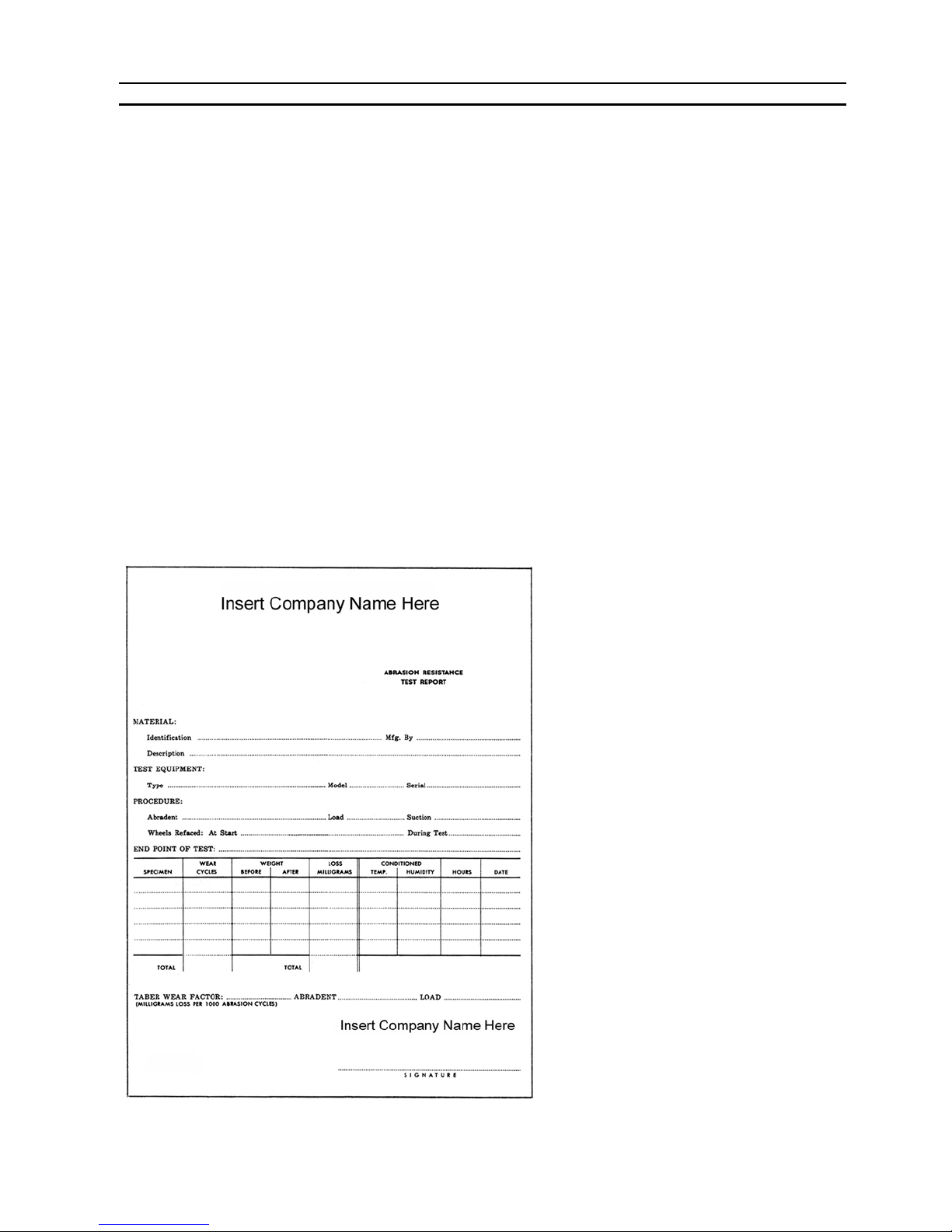
DATA SHEET
The following section provides a brief guideline on developing a data sheet and information that should be
included.
Tested By: Print the name of the test technician.
Signature: For authenticity, have the test technician sign here.
Date: Indicate the date the test was performed.
Product: Indicate or describe the product or type of material being tested.
Notes: Add any special test procedures or other general notes.
Sample No.: For traceability, it is recommended that all test specimens be issued a sample number and that the
sample number be recorded here.
Test No.: It is recommended that all tests on a particular specimen be issued a sequential test number and that
test number be recorded here.
Test Medium: Indicate the test medium used.
Speed: Indicate the speed used in cycles / minute.
Stroke Length: Indicate the stroke length used.
No. of Cycles: Indicate the number of cycles per each test.
Evaluation Criteria:
Hazemeter: The percentage of transmitted light and percent haze, before and after exposure to abrasion.
Appearance Changes: Description of the visual changes.
Weight: The specimen weight prior to starting and after completing the test.
Data Sheet#: Indicate the sequential data sheet number here, for your records.
51 5135 / 5155 Operating Instructions ver 1.1
Page 53

52 5135 / 5155 Operating Instructions ver 1.1
 Loading...