

Page 1
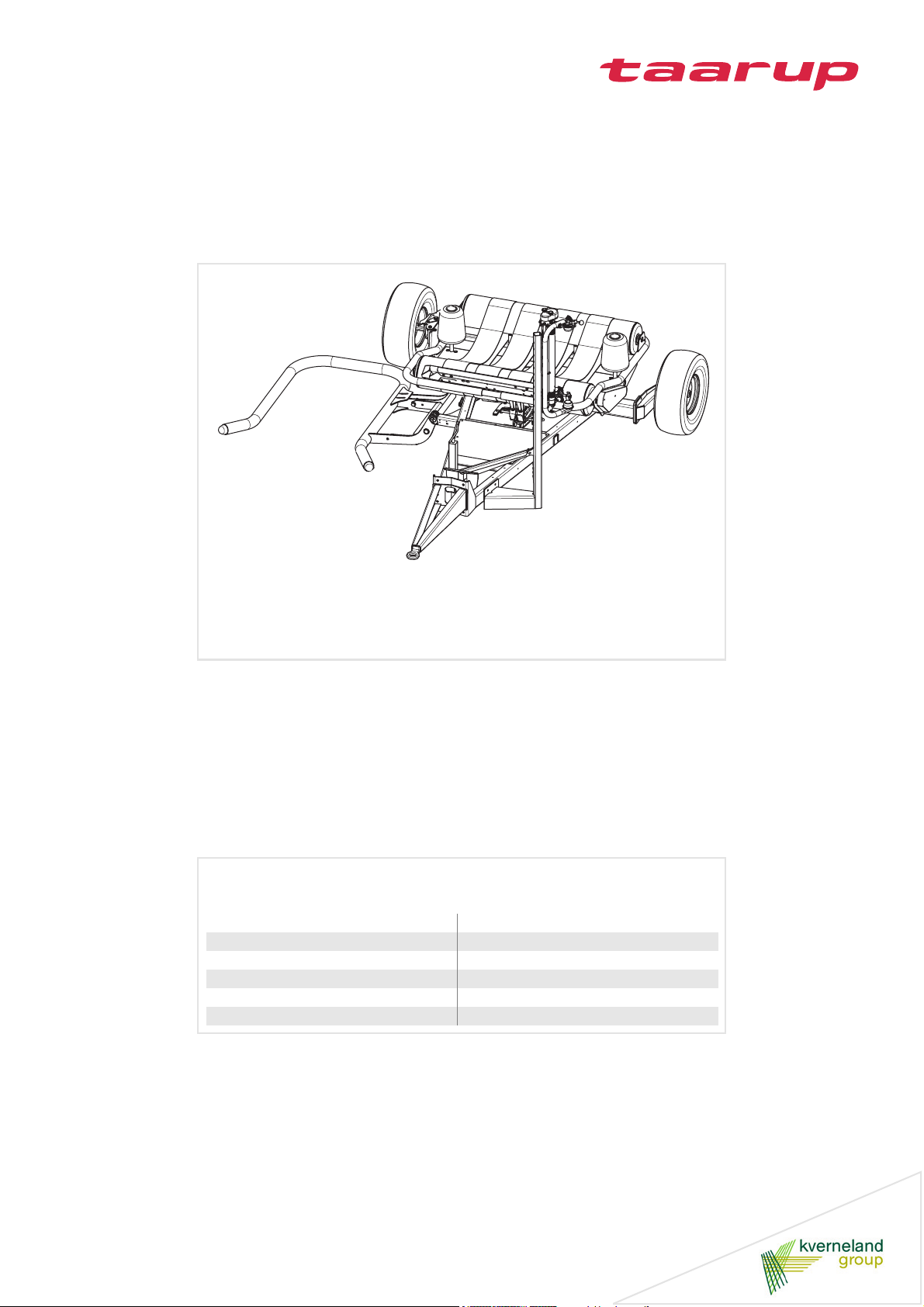
7420
Operation manual
Issue 09/2006
Date of printing 10.2006
Language EN
Ex machine no.(PSN) DW001000
Serial number (PIN) 02DW01
Reference No. VGG0609DW(7)EN
Page 2

Identification of the machine
To support you as soon as possible your dealer requires several details of your machine.
Please enter the information here.
Designation
PIN
Mounted options
Dealer's address
7420
Manufacturer's
address
Kverneland Group Geldrop BV, retains all copyrights and rights of usage. The contents of this operating manual are subject to change without
notice. All rights reserved. The right to technical revision is reserved.
Kverneland Group Geldrop BV
Nuenenseweg 165
5667 KP Geldrop
The Netherlands
Phone +31 40 2893300
Page 3

Table of contents
Preface..............................................................6
Target group of this operation manual 6
Symbols used 7
Safety instructions ..........................................8
For your safety 8
Safety decals at the machine 9
Who is allowed to operate the machine? 13
General 13
Hitching the machine 14
Road transport 15
Working with the machine 16
Unhitching the machine 17
Care and maintenance 18
Further prescriptions 19
Acquaintance with the machine..................20
Destination of the machine 20
Characteristics of the machine 20
Description of the components 21
Technical specifications 22
Delivery and preparation ..............................26
Safety 26
Checking the delivery 26
Preparing the machine 26
Road lighting [+] 26
Hitching the machine ....................................27
Safety 27
General 27
General 28
Support jack 30
Installation cable control 31
Installation control box 32
Hydraulic connections 33
Electronic connections 35
Preparation for use........................................36
Safety 36
Table roller adjustment 37
Support rollers 38
Pre-stretcher 39
Film installation 40
Film overlap 41
Check at beginning of the season 42
Running 42
Road transport...............................................43
Safety 43
Before road transport 43
Road transport 44
Preparation at the field..................................45
Safety 45
Performing settings 45
Prior to wrapping 45
Table of contents
Placing into working position 46
Use at the field............................................... 47
Safety 47
Checks before use 47
Film wrap recommendations 48
Start position mode 49
Wrapping 49
Wrap and bale counter.................................. 51
General 51
Wrap and bale counter box 51
Parameter change 52
Parameter settings 53
Electronic control system ............................55
General 55
Control box 55
Control mode 58
Parameter change 60
Parameter settings 61
Cleaning and caring ...................................... 66
Safety 66
Cleaning 66
Caring 66
Storing the machine...................................... 67
Safety 67
Unhitching and securing of the machine 67
After the season 67
Maintenance................................................... 68
Safety 68
General 70
Attaching elements 72
Tightening torques 73
Pre-stretcher 74
Wheels/tyres 75
Hydraulics 76
Table 77
Applicutter 78
Lubrication 80
Optional equipment....................................... 84
General 84
Standard drawbar 84
Drawbar with eye 84
Drawbar with double tongue 85
High drawbar 85
Film roll holder 85
Wheel chock set 86
Bale turner 86
Drop mat 86
Road lighting 86
Remote control 87
Film break set 87
3
Page 4

Table of contents
Bale counter 87
Troubleshooting ............................................88
Safety 88
Electronic control system 88
Applicutter 89
Pre-stretcher 91
Hydraulics 91
Film 92
Bale 92
Disposal of the machine ...............................93
EC Declaration of conformity ....................... 94
Index ...............................................................95
4
Page 5

Table of contents
5
Page 6

Preface
Preface
Target group of
this operation
manual
This operation manual is meant for those concerned with the control,
use and maintenance of the machine. It contains all data required for
a safe handling, use and maintenance of the machine.
For your safety
Before starting to adjust and use your machine, familiarise yourself
with this operation manual. By doing so your safety and the best performance are assured. It is very important to read this manual carefully
before using the machine and to keep it handy. In this way, you will
• avoid accidents
• respect the warranty conditions
• always have a functional machine in perfect working order
For the employer
All personnel are to be trained in the use of the machine regularly (at
least once a year) in accordance with employers’ liability insurance association guidelines. Untrained or unauthorised individuals are not
permitted to use the machinery.
You are responsible for the safe operation and maintenance of your
machine. You must ensure that you and anyone else who is going to
operate, maintain or work around the unit be familiar with the operating and maintenance procedures and related safety information contained in this manual.
6
Page 7
Preface
Symbols used
In this operation manual the following symbols and terms are used:
• A bullet stands at enumerations
> A triangle stands at steps, which you must do
→ An arrow shows cross-references at other text passages
[+] The plus sign shows that it involves optional equipment, which
does not belong to the standard model.
Besides these symbols, pictograms are used, which will help you with
locating of text passages:
TIPThe word “Tip“ shows tips and advices to the use.
The triangle refers to danger at assembling or (adjusting) work.
The key refers to tips at assembling or adjusting work.
8 The star shows examples, which are needed for a better understand-
ing.
7
Page 8

Safety instructions
Safety instructions
For your safety
This chapter contains all general safety instructions. Subject-specific
safety instructions are located per chapter. Take care of the safety instructions
• because of your own safety
• because of the safety of your fellow man
• to guarantee the machine safety
When handling agricultural machinery, wrong behaviour can lead to a
lot of danger. Therefore work with special care and never under pressure of time.
For the employer
Inform the one who works with this machine frequently about these
safety instructions and according to the legal regulations.
8
Page 9
Safety instructions
Safety decals at
the machine
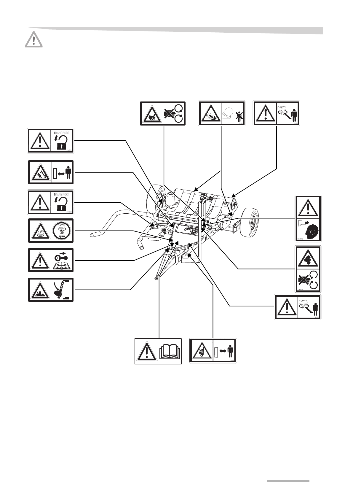
The installed warning and advisory signs give important hints for a
safe operation; adhering to serves your own safety. Keep safety decals and signs clean and legible at all times. Replace safety decals
and signs that are missing or have become illegible. If original parts on
which a safety decal or sign was installed are replaced, be sure that
the replacement part also displays the current decal or sign.
9
Page 10
Safety instructions
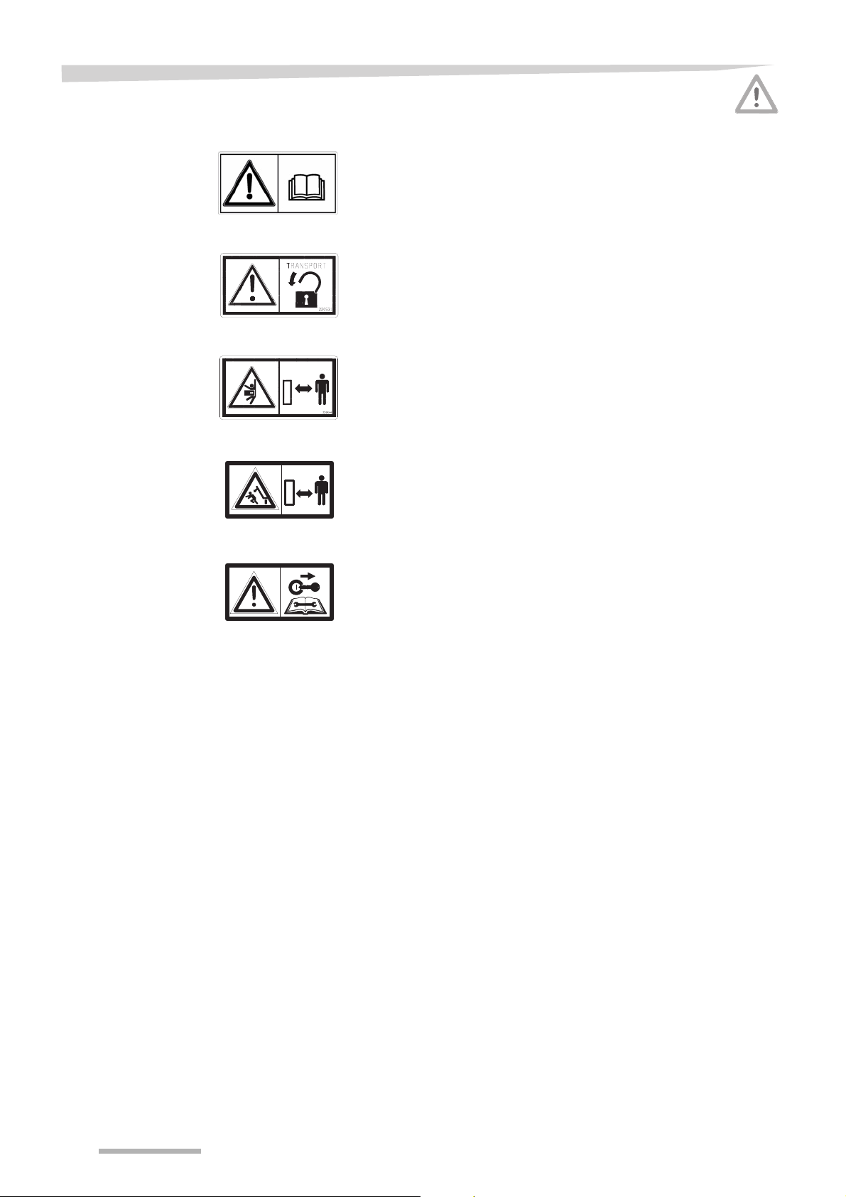
Meaning of the safety
decals
Read the operation manual carefully
Read the operation manual carefully before taking the machine into
operation. Read and obey the safety instructions.
Use the transport lock
Before road transport, the transport lock must be used to secure the
loading arm. A non-secured loading arm can cause serious or deadly
injuries or damages.
Stay clear of the pre-stretcher
Stay clear of the pre-stretcher area while the wrapper arms are rotating. Serious injuries can occur.
Stay clear of the loading arm area
Stay clear of the moving loading arm area. A loading arm moving
down can cause serious personal injuries.
Stop the tractor engine
Prior to any maintenance, repair and adjustment work, stop the tractor
engine and remove the ignition key. Otherwise serious or deadly injuries can occur.
10
Page 11

Safety instructions
Pre-stretcher rotation 30 rpm
The prescribed pre-stretcher rotation of maximum 30 rpm may not be
exceeded.
Use ear protection
Use adequate ear protection during wrapping. Serious hearing injuries
can occur.
Never stay behind the machine while unloading
Stay clear of the table area while unloading a bale. An outcoming, rolling bale has a heavy mass and a high speed. A rolling bale can cause
serious or deadly injuries.
Stay clear of pre-stretcher rollers
Stay clear of the pre-stretcher rollers. Hands can be squeezed between the rollers. Personal injuries can occur.
Stay clear of the pre-stretcher area
Stay clear of the pre-stretcher area while the wrapper arms are rotating. Serious injuries can occur.
11
Page 12
Safety instructions
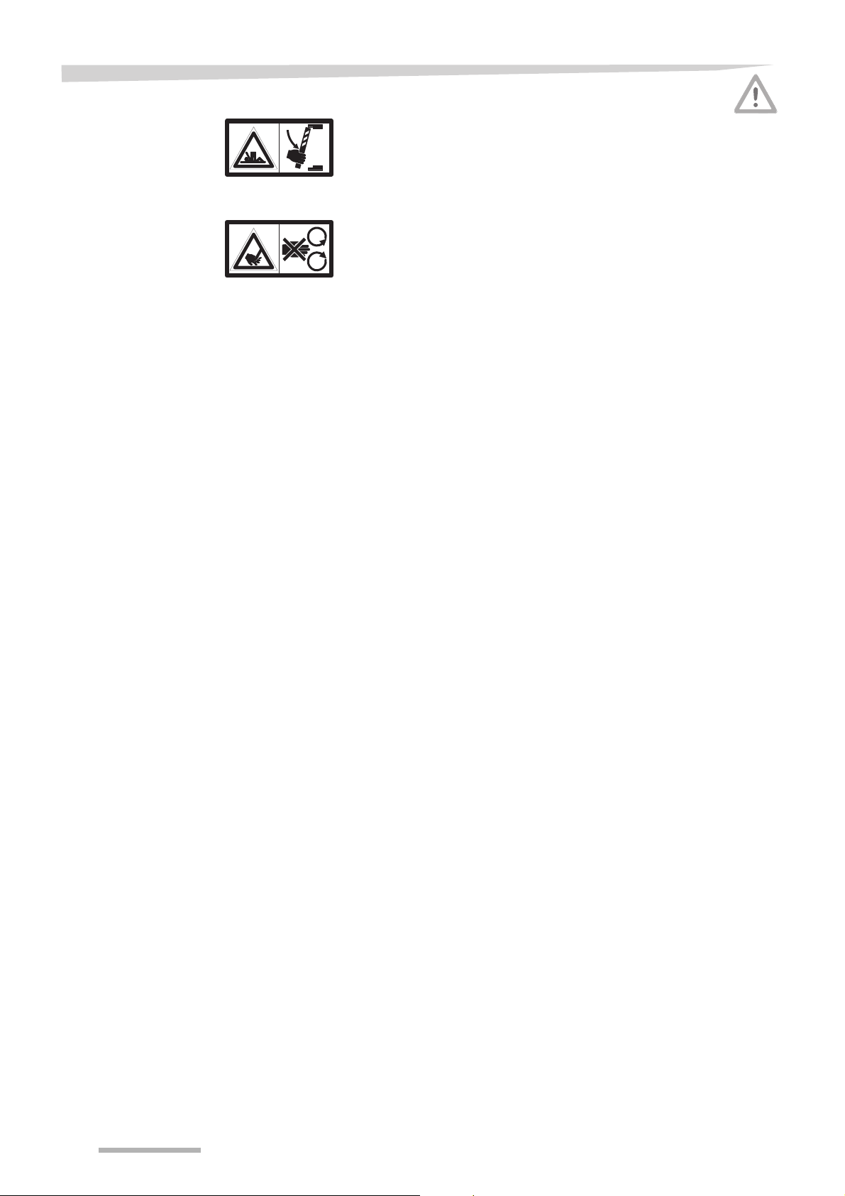
Use the table safety bar
Prior to any maintenance, repair and adjustment work on the tipped table, place the table safety bar. A non-secured table can cause serious
or deadly injuries.
Stay clear of the applicutter rollers
Stay clear of the applicutter rollers. Hands can be squeezed between
the rollers. Personal injuries can occur.
12
Page 13

Safety instructions
Who is allowed to
operate the machine?
General
Authorised people only
The machine may only be used, maintained or repaired by authorised
people who have been informed about the dangers when handling the
machine.
Usually such persons have an agricultural or equal intensive education.
Safety is your responsibility
Apply and insist upon application of the safety instructions. Most accidents are avoidable. Do not run the risk of serious or fatal accidents
through ignorance of these safety instructions.
Wear close fitting clothing
Avoid wearing loose fitting clothing.
Loose clothing can get stuck between rotating parts. Danger of serious injury.
Keep the machine clean
Always keep the machine clean to avoid fire risk. Equip the machine
with a 10 litre pressurised water fire extinguisher to be prepared in
case of fire.
Running in an enclosed area
Do not run the machine in an enclosed area. Exhaust fumes can be
dangerous.
Never work on a running machine
Never work on the machine while it is running. Severe injuries can occur.
No modification of the machine
Do not modify the machine in any way. Unauthorised modifications
may impair the function and/or safety and could affect the life of the
machine.
13
Page 14

Safety instructions
Hitching the machine
Hydraulics
Increased danger of injury
While hitching the machine onto the tractor an increased danger of injury occurs. Therefore:
• prevent the tractor from rolling away, shut down the engine and re-
move the ignition key
• never stay between tractor and machine during hitching
In case of negligence damages to the machine or serious personal injuries can occur.
Hydraulic couplings only pressureless
Only couple the hydraulic hoses to the tractor when both tractor and
machine hydraulics are pressureless. Hydraulics under pressure can
cause accidental movements of the machine.
High pressure in the hydraulic system
The hydraulic system is under high pressure. All tubes, hoses and
couplings must be controlled regularly for leaks and external damages. Only use suitable tools when searching for leaks. Immediately repair damages. Leaking oil can cause injuries and fire. When having injuries visit a doctor immediately.
14
Page 15

Safety instructions
Road transport
Pay attention to a road-safe condition
When driving on the local roads, the machine must correspond to the
current traffic prescriptions. To which e.g. belongs:
• mounting of lighting, warning and protection installations
• comply with the permittable transport dimensions and weights,
maximum permittable axle loads, tyre carrying capacity, total
weights and national speed limits
• taking care of the maximum permitted speed of 25 km/h
In case of negligence, driver and owner of the machine are fully liable.
Prohibition of transporting people on the machine
Nobody and nothing shall be transported on the machine during transport. Transporting of people or objects on the machine is perilous and
prohibited.
Changed driving and braking handling
Because of the hitched machine the driving and braking handling
changes. Especially when driving curves the dimensions and mass of
the machine have to be taken into account. A not adapted driving style
can lead to accidents.
Adapted driving speed
Under bad road circumstances and at high driving speeds very high
crafts can appear, which load or overload the tractor and machine to
much. Adapt the driving speed according to the road circumstances.
A not adapted driving speed can lead to accidents.
15
Page 16

Safety instructions
Working with the
machine
First use only after instruction
The machine may at the first time of use only be brought into use by
employees of the dealer, factory representatives or employees of the
manufacturer. False use after bringing the machine into use without instructions can cause damages to the machine or accidents.
Take care of technical correct condition
Only bring the machine into use in a technical correct condition. Check
all important parts and replace defective parts before use. Defective
parts can cause material or personal damages.
Do not remove protective covers
The protective covers should not be removed or evaded. Check all
protective covers before using. Unprotected machine parts can cause
heavy or deadly accidents.
Prohibition of transporting people on the machine
Nobody and nothing shall be transported on the machine during transport. Transporting of people or objects on the machine is perilous and
prohibited.
Check the direct surroundings
Before driving and bringing into use of the machine the direct surroundings must be checked. Take care of sufficient view. Only start
driving when no persons or objects are in the direct surroundings. Perilous injuries can occur.
Tighten bolts and nuts
Check bolts and nuts regularly for being tight and tighten if necessary.
Because of using the machine bolts can get loose. Damages to the
machine or accidents can be caused.
Behaviour at troubles
At functional troubles stop and secure the machine immediately. Remedy the trouble immediately or commission a workshop. Continuing
working with the machine cause accidents or damages.
Blockage or operation of a security device
In case of a blockage or operation of a security device, never work on
the machine without
• stopping the engine and
• removing the ignition key
Never be tempted to hand feed or unblock the machine while it is running. Serious or deadly injuries can occur.
16
Page 17

Safety instructions
Unhitching the machine
Increased danger of injury
While unhitching the machine from the tractor an increased danger of
injury occurs. Therefore:
• prevent the tractor from rolling away, shut down the engine and re-
move the ignition key
• never stay between tractor and machine during unhitching
• take care of a level and secure surface for the machine
• take care of a secure lock of the support jack
• only detach the hydraulic hoses when the hydraulic system at both
tractor and machine is pressureless
In case of negligence heavy or deadly injuries can be the consequence.
17
Page 18

Safety instructions
Care and maintenance
Observe the care and maintenance intervals
Observe the prescribed intervals and those stated in the operation
manual for recurring checks and inspections. In case of negligence of
the intervals damages to the machine or accidents can be caused.
Use original parts only
Lots of components have special properties which decides for the stability and the function of the machine. Only the parts and options delivered from the manufacturer have been tested and released. Other
products can interrupt the function of the machine or can harm the security. When using not original parts the warranty and liability of the
manufacturer reduces to nil and void.
At all care and maintenance work:
• make the hydraulics pressureless
• switch off the engine and remove the ignition key
• make sure the tractor and machine are positioned on a firm and
level area, support if necessary
• unhitch the tractor if possible
• do not use parts of the machine as climbing help, use suitable
climbing helps on the contrary
Only when observing these prescriptions a secured working during
care and maintenance work is guaranteed.
Interrupt electric power supply
Before working on the electrical device, separate this from the electric
power supply. Supplies being charged can cause material or personal
damages.
Exchange hydraulic hoses
Hydraulic hoses can age without external recognizable indications.
We therefore recommend to exchange all hydraulic hoses every six
years. Defective hydraulic hoses can cause heavy or deadly injuries.
Careful when cleaning with high-pressure cleaner
The machine can partly be cleaned with water or steam. Clean bearings, plastic parts and hydraulic hoses with low pressure only. Too high
pressure can damage these parts.
18
Page 19

Safety instructions
Careful when cleaning with compressed air cleaner
The machine can partly be cleaned with compressed air. Clean electric parts and the hydraulic valve block with low pressure only. Too high
pressure can damage these parts.
No aggressive wax additives
When cleaning do not use aggressive wax additives. Bright metal surfaces can get damaged.
Before welding work
Before welding to the hitched machine, untie the tractor’s battery and
the dynamo. Therefore you will avoid damages to the electrical installation.
Tighten bolted links
After care and maintenance work all loose bolted links must be tightened. Because of loose bolted links material damages can be caused.
Further prescriptions
Observe the prescriptions
Please observe besides these safety instructions
• the accident prevention prescriptions
• the general accredited safety-technical, industrial medicinal and
road traffic law rules
• the tips in this operation manual
• the work, care and maintenance prescriptions
19
Page 20

Acquaintance with the machine
Destination of the
machine
Intended use of the
machine
Characteristics of
the machine
This chapter contains general information about your machine and information about:
Acquaintance with the machine
• characteristics
• technical specifications
This machine is exclusively appropriate designed for film wrapping of
round bales of ligneous plants, mainly grasses, taking into account all
prescriptions, procedures, etcetera as stated herein and/or through
decals or other signs on the machine.
This machine shall be exclusively used for the normal agricultural
work.
Any use beyond the one stipulated above requires written authorization of the manufacturer, this may be required for film wrapping unusual, non-grass plants as well.
The loading arm picks up, lifts the bale and puts it onto the table. The
table starts rotating. The bale is being wrapped with film. When the desired number of film wraps is reached, the table stops rotating. The
film is cut by the applicutter. The bale will be unloaded by tipping backward the table.
20
Page 21
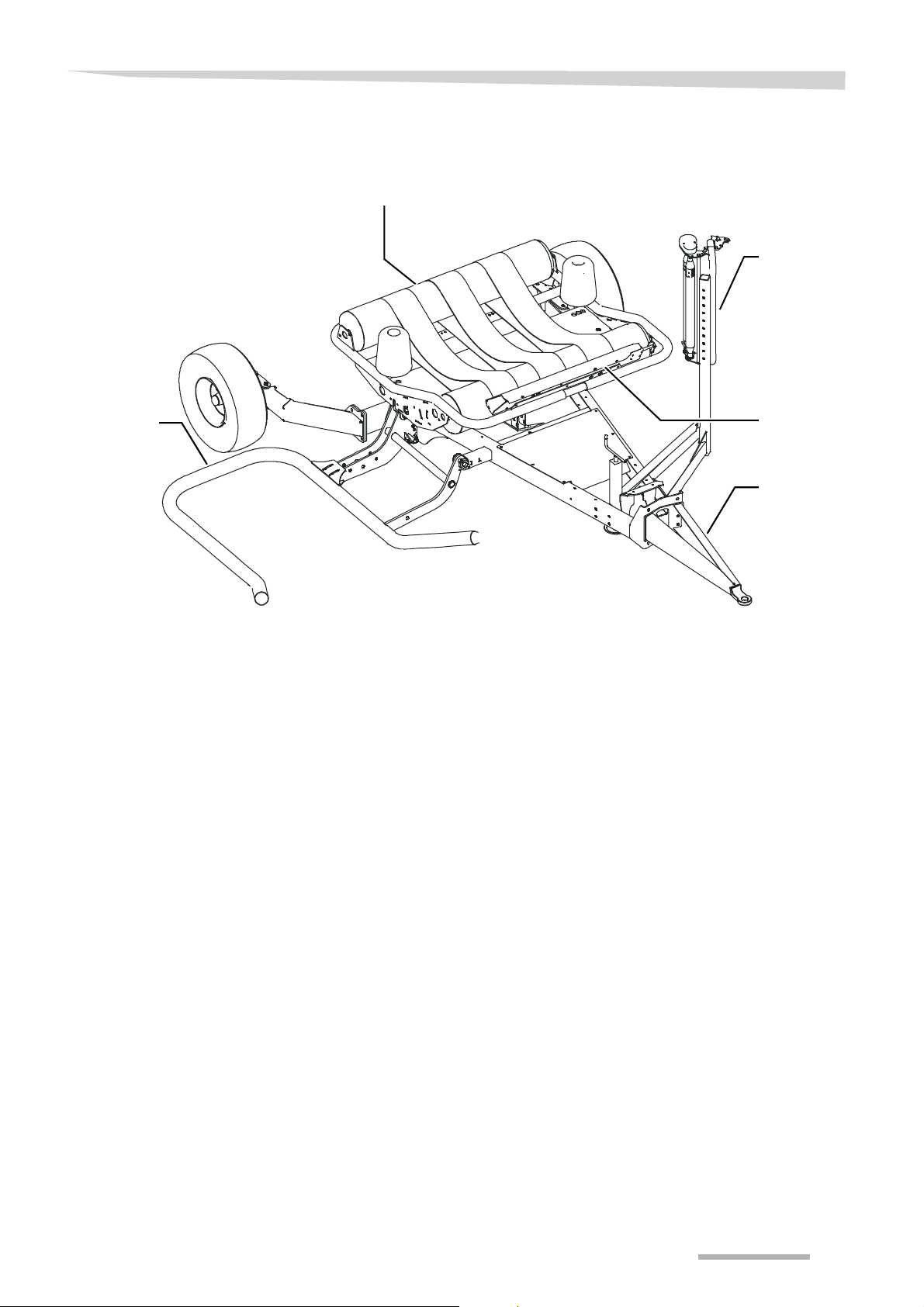
Description of the
components
Acquaintance with the machine
Table
Pre-stretcher
Loading arm
Applicutter
Drawbar
21
Page 22
Acquaintance with the machine
Technical specifications
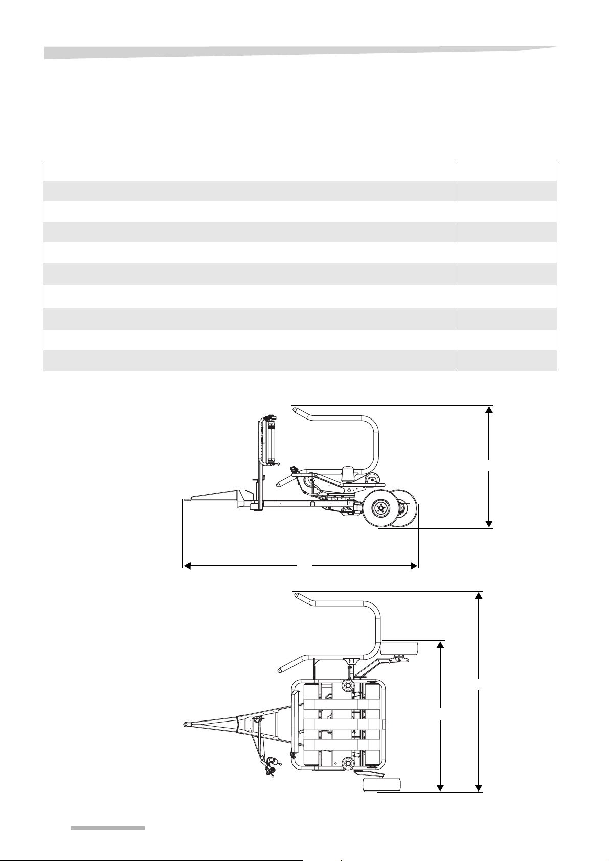
Dimensions / weight
Weight
Maximum weight (kg) 1,000
Length (m)
Overall length 4.55 (L)
Width (m)
Overall width with loading arm folded up and right wheel in transport position 2.45 (W2)
Overall width with loading arm folded up with both left and right wheel in transport position 2.18 (W
Overall width with loading arm folded down 3.75 (W1)
Height (m)
Overall height with loading arm folded up 2.28 (H)
H
L
)
2
22
W
1
W
2
Page 23

Bale requirements
Round bales
Minimum diameter (cm) 100
Maximum diameter (cm) 150
Maximum weight (kg) 1.000
Acquaintance with the machine
Maximum
150 cm
23
Page 24

Acquaintance with the machine
Optional equipment
Film roll holder
Road lighting set
Film break kit
Drop mat
Bale turner
Adapter for 500 mm film rolls
Remote control
Wheel chocks
Wrap and bale counter
Tractor requirements
Tractor requirements
Electronics 12 V (DC) coupling for control box
(DIN 9680)
12 V (DC) coupling for road lighting
(DIN ISO 1724) [+]
Hydraulics 1 single acting control valve with pres-
sureless return
Pump capacity (l/min) 26
Pressure (bar) 150
24
Page 25

Acquaintance with the machine
Machine requirements
Tyres
standard 11.0/65-12
Maximum transport speed (km/h) 25
Maximum satellite rpm 30
Film requirements
Film width (mm) 750
Alternative film width (mm) 500
Minimum film thickness (µm) 25
Quality 3-layer blown film
25
Page 26
Delivery and preparation
Delivery and preparation
Safety
Checking the delivery
Preparing the machine
Wear safety shoes
During all work at the machine never bring your feet under the machine and always wear safety shoes. Wearing safety shoes prevents
or decreases the risk of serious injuries.
Completely delivered
The machine is delivered completely. In case parts are not present,
please contact your dealer.
The machine must be checked after delivery. The machine is
equipped with:
• Operation manual
• Spare parts manual
• Hydraulic hose with coupling
• Cable control [+]
• Electronic control system (control box, fixing brackets, power ca-
ble) [+]
The machine must be prepared before taking into use is possible.
The following must be prepared:
• the road lighting [+]
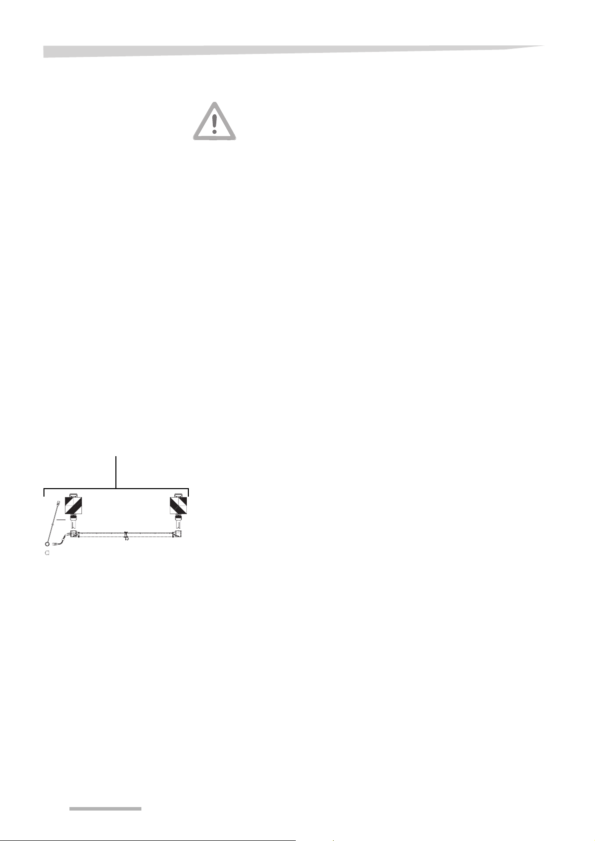
Road lighting [+]
Road lighting
The road lighting must be mounted according to the assembly instruction.
> Mount the road lighting at the places provided
26
Page 27

Hitching the machine
Hitching the machine
Safety
General
Increased danger of injury
• Prevent the tractor from rolling away
• Never stay between the tractor and the machine during hitching
In case of negligence serious or deadly injuries can occur.
Use a proper tractor
Make sure the tractor
• is in safe operating condition
• has adequate braking capabilities for this machine
• is suitable for carrying and transporting this machine
Using a tractor which is not suitable can cause serious personal and
material damages.
The machine is provided for hitching to the towing hook of the tractor.
To prepare the machine for hitching, the following items are necessary:
• Both tractor and machine must be placed on a firm level
• The machine must be levelled horizontally
• The hydraulic hoses must be coupled
• The lighting cables [+] must be coupled
• The cable control [+] must be installed
or
• The electronic control box [+] must be installed
27
Page 28
Hitching the machine
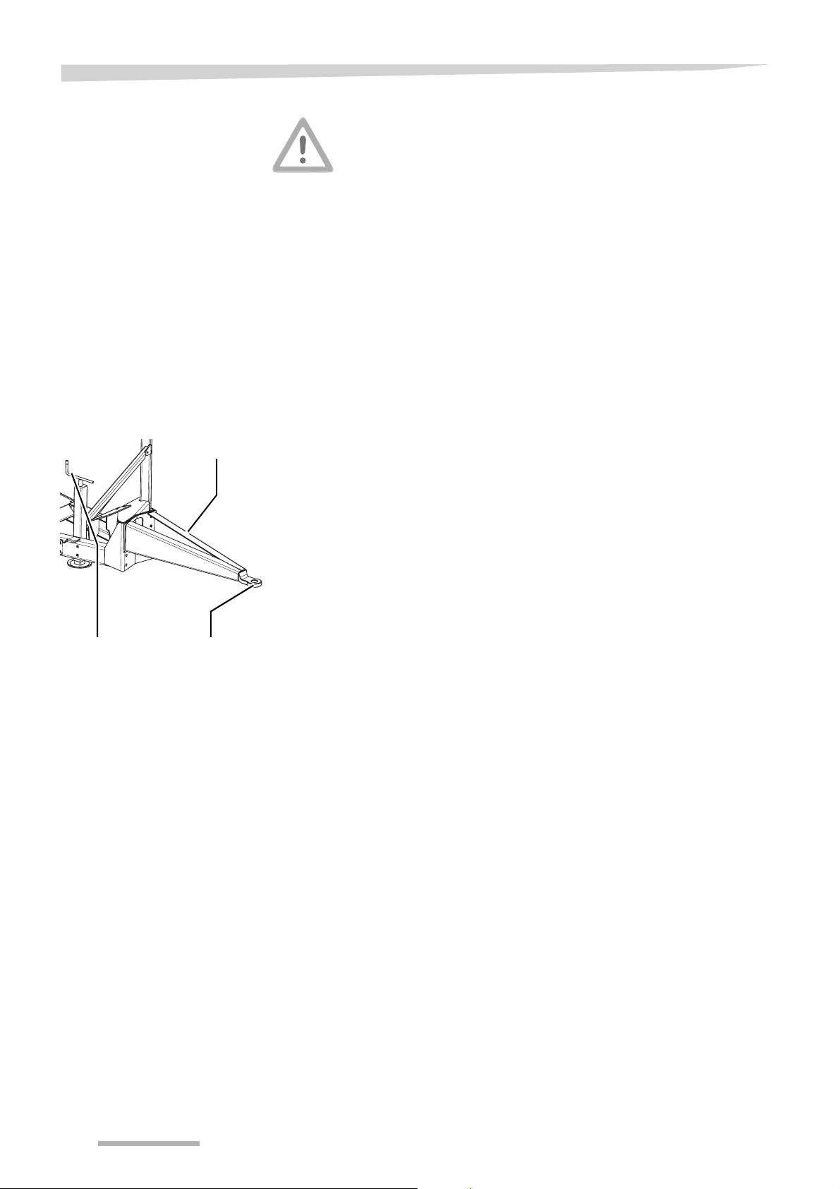
General
Drawbar adjustment
Drawbar
Remove the tractor lower links
Remove the lower links of the tractor to avoid them touching the drawbar. During turning, the lower links of the tractor can touch the drawbar
and the machine can tip over. Personal or machine damages can occur.
The machine is ex works provided for hitching to the towing hook of
the tractor.
Before the machine can be hitched to the towing hook of the tractor,
the correct height of the hitch eye to the towing hook of the tractor
must be determined.
> Place both tractor and machine in line on a firm level, with a dis-
tance between the towing hook of the tractor and the hitch eye of
about 15 cm
If necessary, the drawbar can be turned upside down. Doing this, the
drawbar can be set for high or low attachment.
Four drawbar types exist:
• standard drawbar
• drawbar with eye
• drawbar with double tongue
• high drawbar
→ Optional equipment, page 84
Handle Hitch eye
The machine must be placed in a horizontal position:
> Turn the handle to the left: the drawbar goes upwards
or
> Turn the handle to the right: the drawbar goes downwards
> Check the height of the towing hook of the tractor
The drawbar height can be changed by moving the drawbar. The
drawbar can be placed into six positions.
Select the correct position in accordance with your tractor in order to
have tractor and machine lined up correctly.
→ Moving the drawbar, page 29
28
Page 29
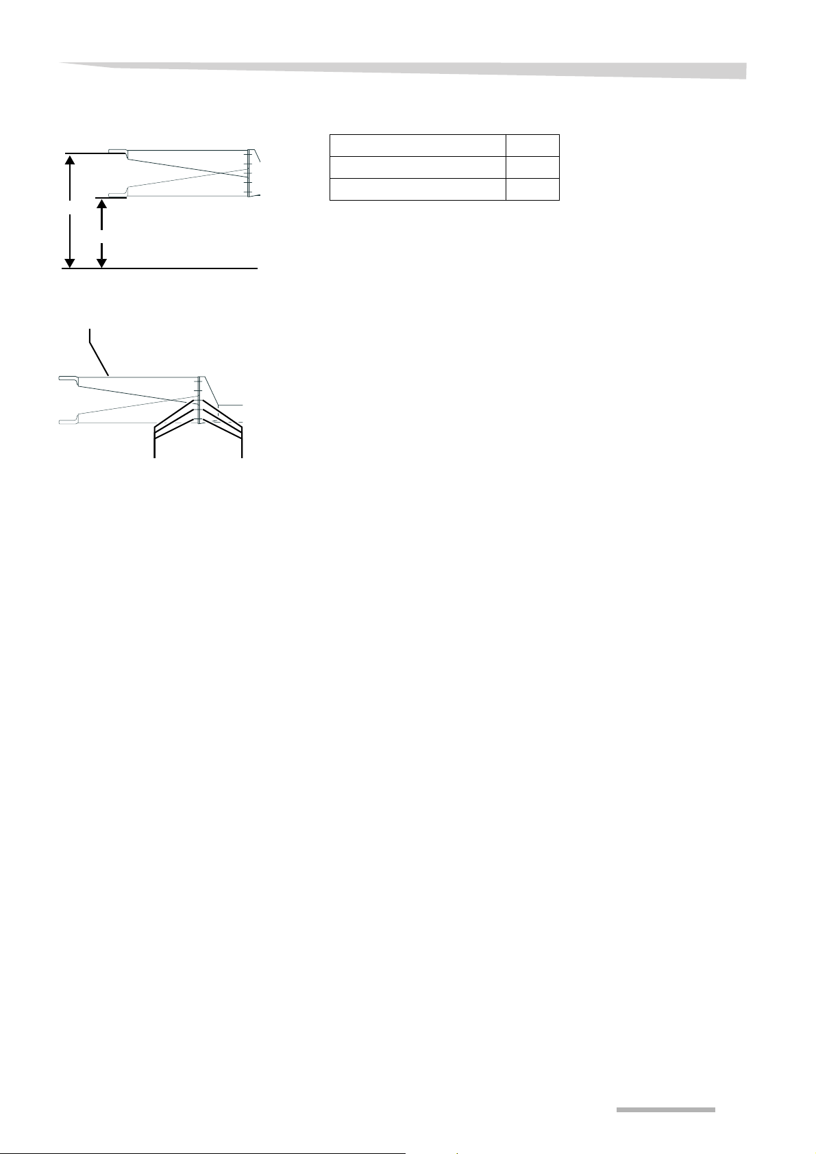
Moving the drawbar
69
36
Drawbar
Hitching the machine
Towing hook height (cm) Cm
Minimum 36
Maximum 69
> Secure the drawbar by placing it in a well suited hoist
> Loosen the bolts and nuts
> Move the drawbar to the desired position
The drawbar must always be fitted with 3 bolts and nuts per side.
> Tighten the bolts and nuts
> Torque the bolts and nuts to 220 Nm
> Remove the hoist
Hitching
BoltsNuts
> Hitch and secure the machine to the towing hook of the tractor
29
Page 30
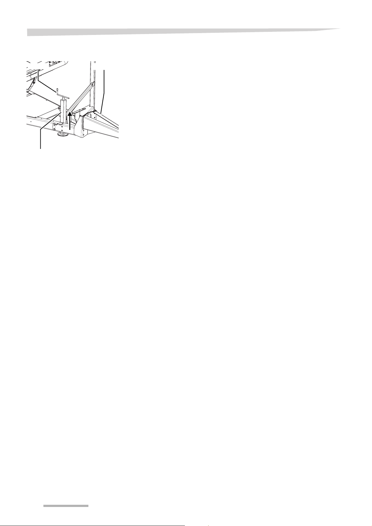
Hitching the machine
Support jack
DrawbarHandle
Support
jack
> Fully retract the support jack using the handle
30
Page 31
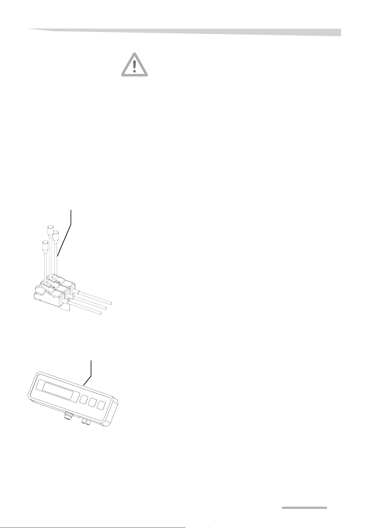
Hitching the machine
Installation cable
control
Mounting and connecting
Cable control
Check correct lying of the cables
Cables may not get stretched or get trapped. Take care of sufficient
free space. Torn or trapped cables can lead to unpredictable movements of the machine and can lead to serious damages and injuries.
The cable control must be installed on a support or holder in the tractor
cab.
Take care of the following:
• Ensure the cable control is installed in good manual and visible
reach of the operator
• Do not mount the cable control onto a part that is subject to strong
vibrations
• Ensure the cable control is in an area with less dust
• Avoid sharp bends in the cables
> Mount and connect the cable control at the tractor
Rotation and bale
counter
Rotation and
bale counter
The rotation and bale counter must be mounted and connected.
31
Page 32
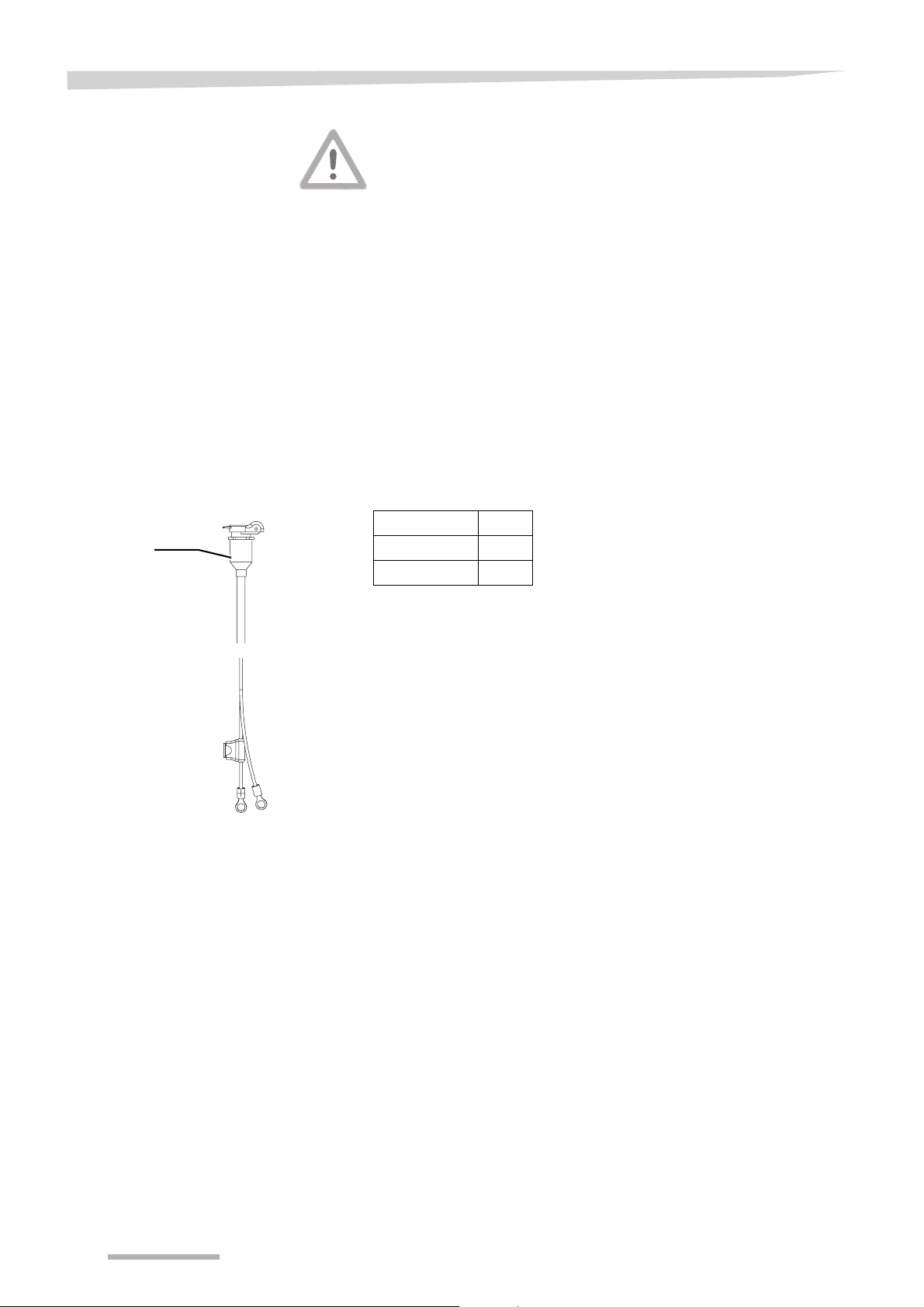
Hitching the machine
Installation control box
Electrical connections control box
Connection to
control box
Correct connection of the electronic control system
Never connect the cable to the cigarette lighter because of interference risk. Always connect the cable directly to the interference-free
power source. Therefore check the functioning of the fuses on the
power cables.
The control box must be installed on a support or holder in the tractor
cab.
Take care of the following:
• Ensure the control box is installed in good manual and visible
reach of the operator
• Do not mount the control box onto a part that is subject to strong
vibrations
• Ensure the control box is in an area with less dust
• Do not install the control box where bright sun or rain may reach it
> Connect the main power cable of the machine box directly to the
12V battery of the tractor
Cable code Pole
++
--
> Connect the 4-pin connectors of the control box and machine box
to each other
32
Page 33

Hitching the machine
Hydraulic connections
Hydraulic coupling only pressureless
Only couple the hydraulic hoses to the tractor when both tractor and
machine hydraulics are pressureless. Hydraulics under pressure can
cause accidental movements of the machine.
Avoid oil mixture
When using the machine in combination with different tractors, improper oil mixture can take place. Improper oil mixture can destroy
tractor parts.
Avoid entering of dirt into the hydraulic system
The hydraulic system can get seriously damaged. Personal injuries or
material damage can be caused.
Check hoses and couplings
Before connecting, prove all hydraulic hoses for damages. After connecting check all hydraulic couplings for tight connection. Defective
hydraulic hoses or bad connected hydraulic couplings can cause injuries or unforeseen movements of the machine.
Secure tractor hydraulic devices
In transport position tractor hydraulic devices must be secured against
unintentional movements. Unintentional movements of the hydraulic
device can cause serious injuries or unforeseen movements of the
machine.
Check correct position of hydraulic hoses
Hydraulic hoses may not stick or tighten. Pay attention to sufficient
free space. Torn or stuck hydraulic hoses cause unverifiable movements of the machine and serious injuries.
Take care of the correct laying of hydraulic hoses
Hydraulic hoses may not stick or tighten. Take care of sufficient free
space. Worn or stuck hydraulic hoses can cause heavy damage to the
machine or severe injuries.
Check, if applicable, the following connections from the tractor to the
machine:
• hydraulic connections
• electronic connections
Before coupling, the hydraulic block must be adapted:
• Hydraulic block - open centre
• Hydraulic block - closed centre
• Hydraulic block - load sensing
33
Page 34
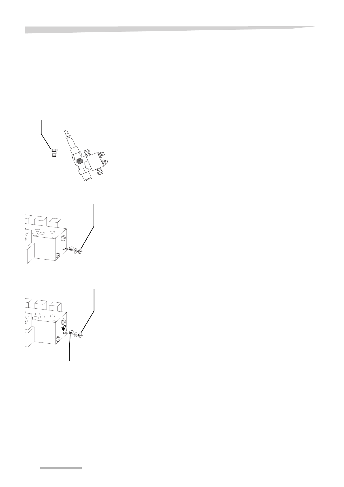
Hitching the machine
Hydraulic block open centre
Hydraulic block closed centre
Cable control
Blocking plug
Electronic control
Main plug
The machine is standardly adjusted for tractors with an open centre
hydraulic system.
No adjustment of the hydraulic block is necessary.
When the tractor is provided with a closed centre hydraulic system,
the hydraulic block must be adjusted accordingly.
When the machine is provided with a cable control the hydraulic block
must be adjusted accordingly.
> Switch off the tractor engine and remove the ignition key
> Mount the blocking plug
When the machine is provided with an electronic control the hydraulic
block must be adjusted accordingly.
> Switch off the tractor engine and remove the ignition key
Blocking bolt
Main plug
> Remove the main plug
> Mount the blocking bolt
> Mount the main plug
34
Page 35

Hitching the machine
Hydraulic block - load
sensing
Hydraulic hose
Electronic connections
The machine is standardly adjusted for tractors with an open centre
hydraulic system.
No adjustment of the hydraulic block is necessary.
The oil flow of the tractor must be adjusted to 26 l/min.
> Make sure the tractor hydraulic device is pressureless
> Couple the hydraulic coupling to a single or to a double acting hy-
draulic device with pressureless return
Check cables and couplings
Before connecting, prove all electronic cables for damages. After connecting check all electronic couplings for tight connection. Defective
electronic cables or bad connected electronic couplings can cause injuries or unforeseen movements of the machine.
Check correct position of electronic cables
Cables hoses may not stick or tighten. Pay attention to sufficient free
space. Torn or stuck electronic cables cause unverifiable movements
of the machine and serious injuries.
Take care of the correct laying of electronic cables
Electronic cables may not stick or tighten. Take care of sufficient free
space. Worn or stuck electronic cables can cause heavy damage to
the machine or severe injuries.
Electric lighting [+]
> Connect the 7-pin plug to the trailer lighting socket on the tractor
35
Page 36

Preparation for use
Preparation for use
Safety
Obey safety instructions
Obey the safety instructions at the execution of all work. Ignoring the
safety instructions can lead to serious or deadly injuries.
Guarantee correct hydraulic coupling
Check before using if all hydraulic couplings are coupled correct to the
single and double acting valves. Not correct coupled hydraulic couplings can cause unpredictable movements of the machine.
Never work on the machine while it is running
Never carry out adjustment work while the machine is running.
• The tractor engine must be switched off and the ignition key must
be removed
• The electronic control box must be switched off
In case of negligence, serious or deadly injuries can occur.
No persons in turning area
During work, no persons may be within the turning area of the machine, including the satellite area. Serious personal injuries can be
caused.
Secure the machine
During adjustment, an increased danger of injury exists. Therefore
• secure the machine from accidental commencement of operations
and rolling away
• the machine must have a level, secure position and must be sup-
ported during working if necessary
Unsecured or not supported machines can lead to accidents.
Wear safety shoes
During all work at the machine never bring your feet under the machine and always wear safety shoes. Wearing safety shoes prevents
or decreases the risk of serious injuries.
Guarantee correct hydraulic coupling
Check definitely, before using the machine, if the hydraulics for the
system are coupled to the correct single acting valves with pressureless return. Not correct coupled hydraulic hoses can cause accidental
movements of the machine.
The following preparations have to be done:
• table roller adjustment
• support rollers adjustment
• pre-stretcher adjustment
• film installation
• film overlap
36
Page 37

Preparation for use
Table roller adjustment
Front position Rear position
Table roller Bolts
To ensure good stability of the bale during wrapping, the table roller
must be adjusted for small or large bales.
Recommended position, depending on the bale diameter:
Bale size (m) Recommended position
until 1.30 front
over 1.30 rear
To prevent the table roller from unintented moving:
> support the roller
> Remove the bolts
> Move the roller to the desired setting
> Tighten the bolts
> Remove the support of the roller
37
Page 38
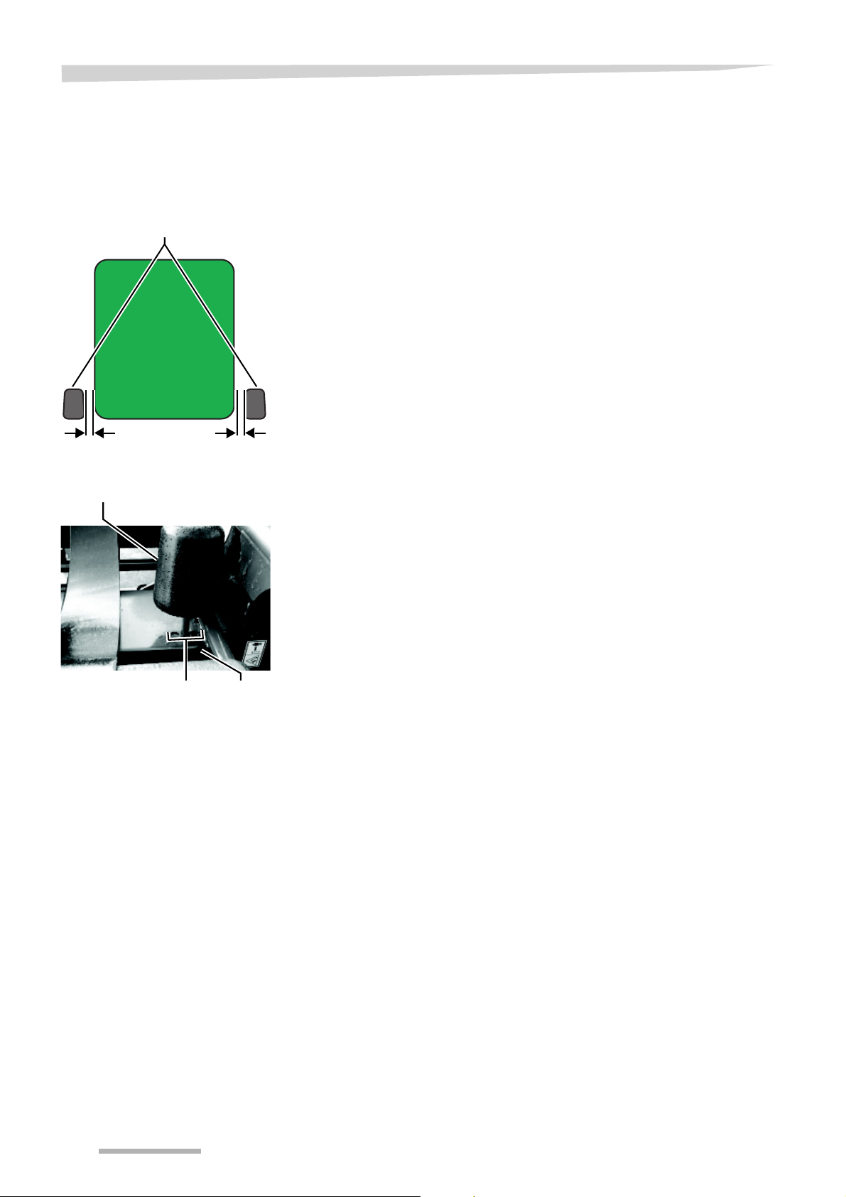
Preparation for use
Support rollers
Support rollers adjustment
Support rollers
C C
Support roller
To ensure a good stability of the bale during wrapping, the support rollers can be adjusted for small or large bales.
The support roller must be adjusted so, that the bale is in the middle
of the table. When the bale is on the table, the clearance C on both
sides between the bale and both support rollers should be maximum
150 mm.
The support rollers can be placed in three positions. The middle or the
right hole are recommended.
> Remove the linch pin
> Place the roller in the correct hole, to adjust to clearance C
> Place the linch pin
Holes Linch pin
38
Page 39
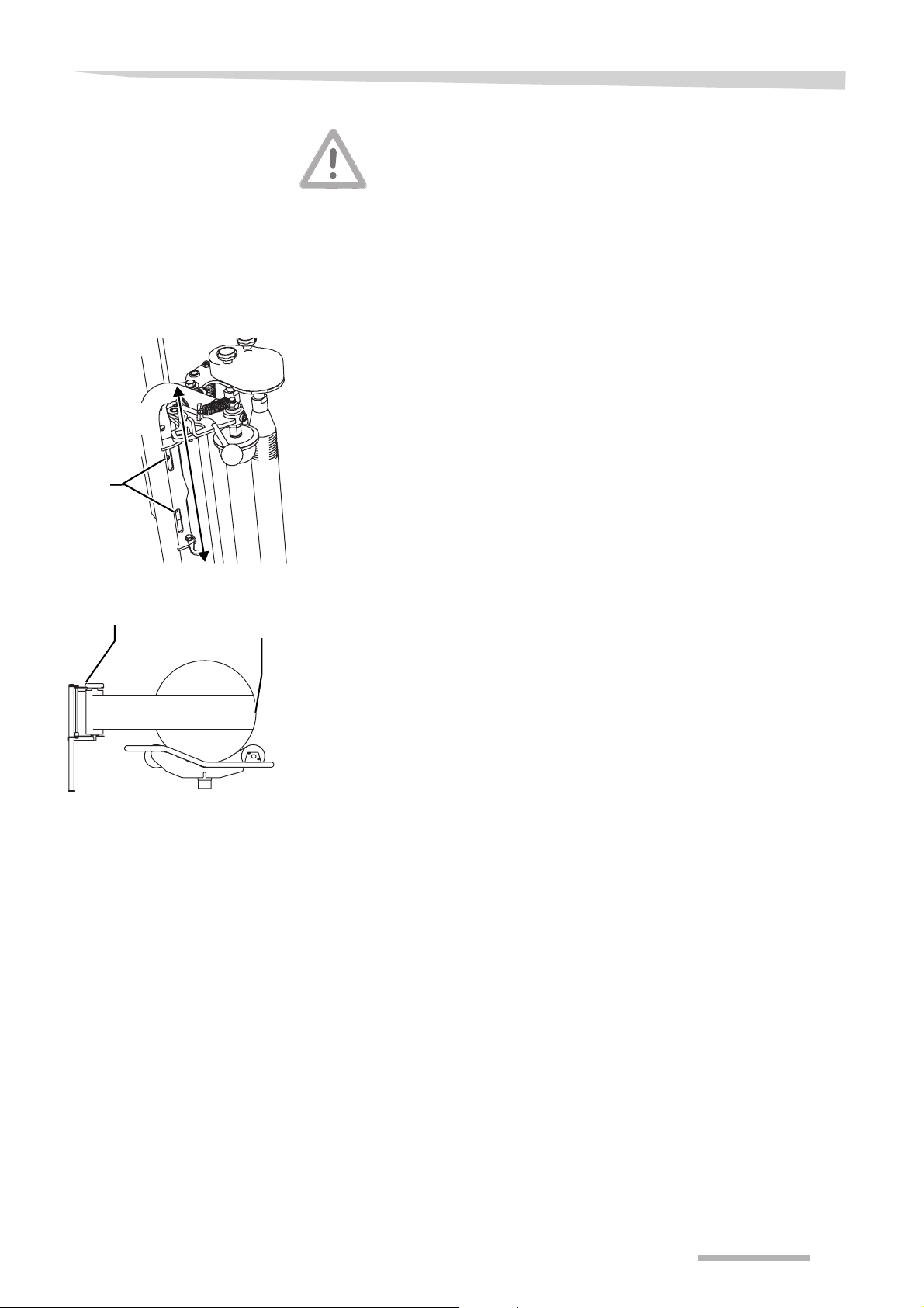
Preparation for use
Pre-stretcher
Pre-stretcher adjustment
Bolts
Wear safety shoes
During all work at the machine never bring your feet under the machine and always wear safety shoes. Wearing safety shoes prevents
or decreases the risk of serious injuries.
The pre-stretcher must be adjusted so, that the centre of the film roll
matches the centre of the bale.
> Switch off the tractor engine and remove the ignition key
> Loosen the bolts one turn
> Move the entire pre-stretcher upwards or downwards, depending
on the bale diameter and the kind of bales to be wrapped
Pre-stretcher
Centre of
the bale
The centre of the film roll must now match the centre of the bale.
> Tighten the bolts
39
Page 40
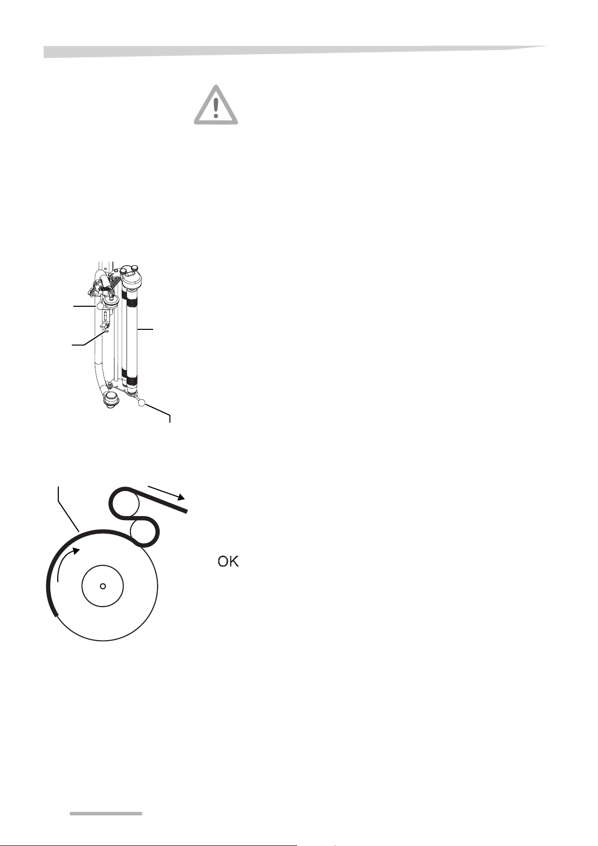
Preparation for use
Film installation
Loading the film roll
Upper
lever
Prestretcher
Hook
Before installing the film:
> switch off the tractor engine
> remove the ignition key
Stay clear of pre-stretcher rollers
Stay clear of the pre-stretcher rollers. Hands can be squeezed between the rollers. Personal injuries can occur.
Choose a good quality of film in order to ensure troublefree functioning
of the film wrap system. Recommended is
→ Film requirements, page 25
> Move the lower lever to secure the pre-stretcher with the hook
> Release and lift the upper lever
In case a 500-mm film roll is used:
> place an adapter [+] on top of the film roll
> Place a film roll
Take care of the right direction of rotation of the film roll.
> Lower the upper lever
Film
Lower
lever
> Guide the film between the pre-stretcher, according to direction of
the arrows
> Move the lower lever to unsecure the pre-stretcher from the hook
> Connect the end of the film to the applicutter
Electronic control only:
> push for a counter/programme reset
40
Page 41
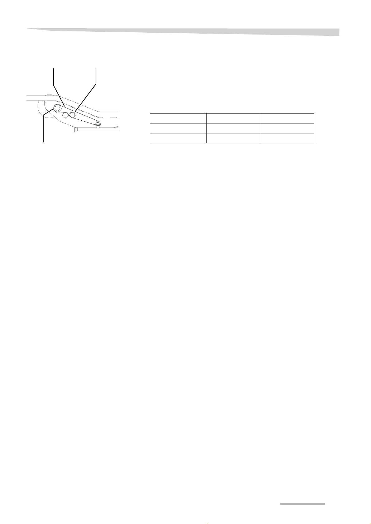
Preparation for use
Film overlap
Chain tensionerChain
Sprocket
The film overloap is determined by the rotation speed of the table
belts. The speed of the table belts can be varied by mounting a different sprocket.
A 12-teeth sprocket is standard mounted. In case a pre-stretcher
adapter for 500 mm film rolls [+] is mounted, an 18-teeth sprocket can
be mounted.
Recommended setting, depending on the desired film roll width:
Film width (mm) Sprocket (teeth) Film overlap (%)
500 18 50
750 12 50
Exchanging the sprocket:
> Loosen the chain tensioner
> Remove the chain
> Remove the sprocket
> Mount the desired sprocket
> Mount the chain
> Tighten the chain tensioner
41
Page 42

Preparation for use
Check at beginning of the season
Running
The following items have to be checked before using the machine at
the beginning of the season:
• Check the electric connections
→ Electrical connections control box, page 32
• Check the road lighting [+]
→ Road lighting [+], page 26
• Check the lubrication
→ Maintenance intervals, page 71
• Check the tyre pressure
→ Tyre pressure, page 75
> Run the tractor hydraulics at idle
• Check the correct operation of the components
• Check, if there are no unusual noises
> Switch off the tractor hydraulics
• Check the tightness of the hardware
During the running-in period, a specific maintenance must be done,
confer to maintenance chart
→ Maintenance intervals, page 71
42
Page 43
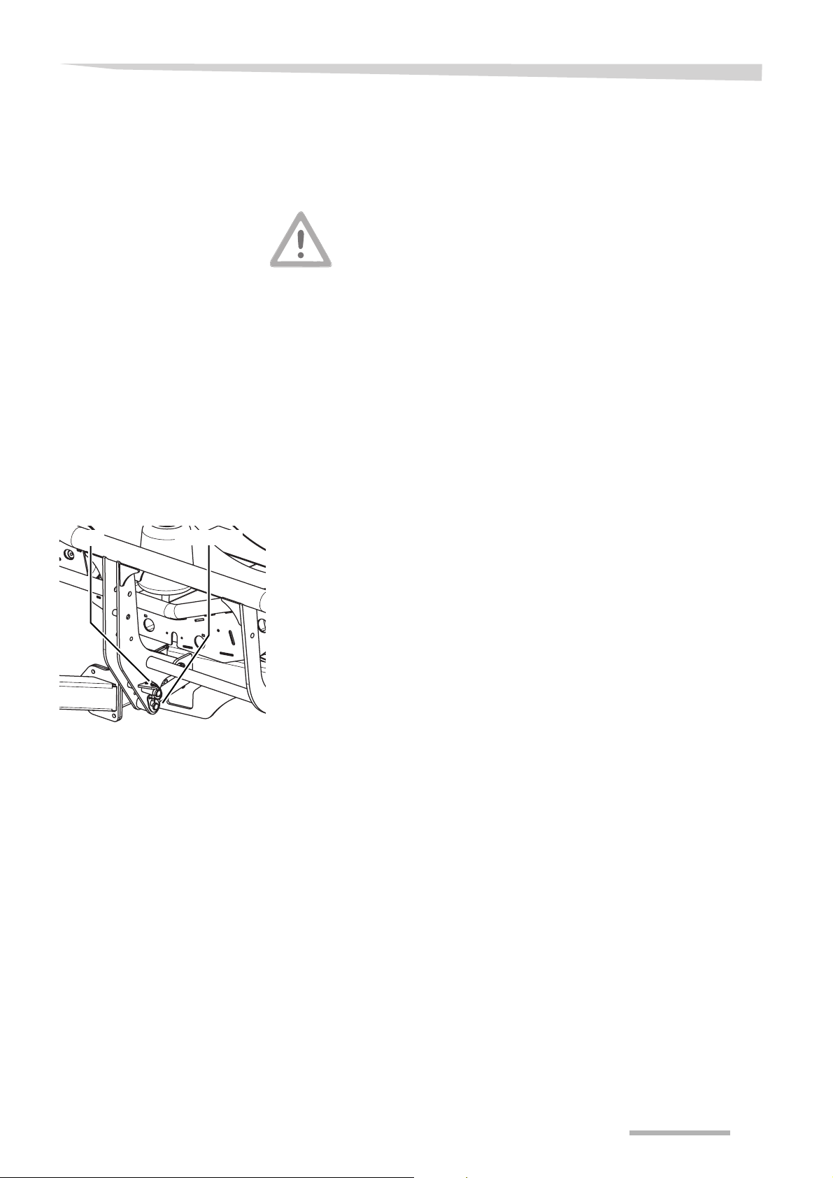
Road transport
Road transport
Safety
Before road transport
Loading arm lock
Locking pinPin
Before road transport will take place, please read the following safety
instructions. The compliance is prescribed and helps you to avoid accidents.
Close valves
Before road transport close all valves. With open valves and false operation the lifting cylinder can be lowered. Traffic accidents can be
caused.
Clean the machine before road transport
Clean the machine, before every road transport, from crop residues
and heavy dirt. Crop or dirt, falling at the road, can cause a slippery
state of the road. This can lead to fatal accidents.
Road transport must be done in transport position. To bring the machine into transport position, the following steps are necessary:
• the table must be fully tipped forwards
• the loading arm lock must be applied
• the right wheel must be in transport position
The loading arm must be locked into transport position.
> Move up the loading arm completely
> Mount the pin
> Lock the pin with the locking pin
The locking pin must be in the left hole.
43
Page 44
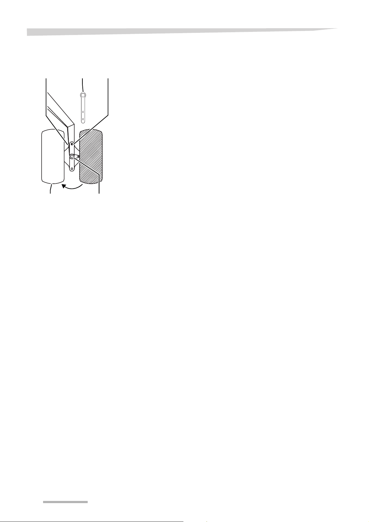
Road transport
Right wheel in transport position
Locking pin Pin
Transport position Hexagon bolt
Wrench
Checking the machine
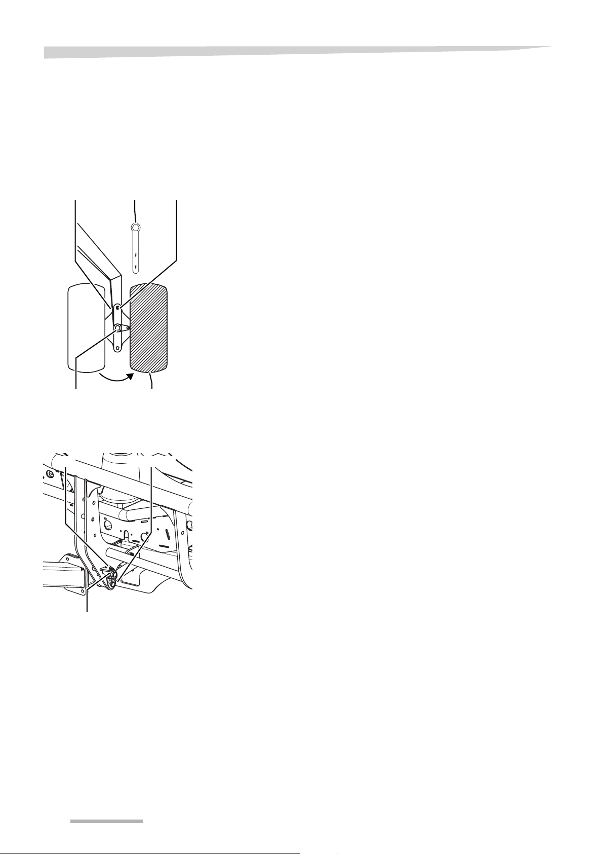
The right wheel must be in transport position.
> Remove the locking pin
> Remove the pin
> Place the wrench on the hexagon bolt
> Use the wrench to turn the wheel into transport position
> Place the pin
> Place the locking pin
> Remove the wrench
Check the machine before road transport by means of the checklist:
• The tractor hydraulic is switched off?
• All valves are closed?
• Crop residues and heavy dirt are removed?
• Cables and lines are placed in that way they will not tension or get
in touch with the tractor rear tyres during curve driving?
Road transport
• Before starting driving, check the close environment. Always take
care of a clear view and especially at children in the working environment of the machine.
• Lock the hydraulic valves of the tractor before road transport
• Do not transport any persons or objects at the machine
• Adapt the drive speed to the road conditions
• Do not exceed the maximum speed of 25 km/h. Obey the national
and local speed limits.
• Pay attention to sufficient driving and braking capacity. Then driv-
ing and braking capacity are influenced by the attached machine
(longer braking paths because of larger driving power).
44
Page 45

Preparation at the field
Preparation at the field
Safety
Performing settings
Prior to wrapping
Obey the safety instructions
Obey the safety instructions at the execution of all work. Ignoring the
safety information can lead to serious or deadly injuries.
Secure tractor and machine
• Switch off and secure the tractor
• Prevent the machine against accidental commencement of opera-
tions
Unsecured machines and tractors can lead to accidents.
The settings to the machine must be performed in working position.
They are described in the next sections:
• Prior to wrapping
• Placing into working position
Before wrapping can start, the following has to be checked:
• Has the loading arm been placed into working position?
• Has the right wheel been placed into working position?
The machine has to be adapted to the type of the bale and the size of
the bales wrapped
• Is the number of table rotations ok?
• Is the pre-stretcher height ok?
45
Page 46
Preparation at the field
Placing into working position
Right wheel in working position
Locking pin Pin
Wrench
The machine must be used in working position. To bring the machine
into working position, the following steps are necessary:
• the right wheel must be in working position
• the loading arm lock must be removed
The right wheel must be in working position.
> Remove the locking pin
> Remove the pin
> Place the wrench on the hexagon bolt
> Use the wrench to turn the wheel into working position
> Place the pin
> Place the locking pin
> Remove the wrench
Hexagon bolt
Working position
Loading arm lock
Locking pinPin
Right hole
The loading arm must be placed into working position.
> Remove the locking pin
> Remove the pin
> Move down the loading arm completely
> Mount the pin
> Lock the pin with the locking pin
The locking pin must be in the right hole.
46
Page 47

Use at the field
Use at the field
Safety
Checks before use
Driving along at the machine prohibited
It is never allowed that people or objects drive along at the machine.
Driving along at the machine is perilous and prohibited.
No persons in the turning area
Take care of no people be in the turning and working area of the machine. People can get grabbed by the machine within this area. Serious or deadly injuries can occur.
No persons in the folding area
Take care of no people be in the folding area of the machine. People
can get crushed by the machine within this area. Serious or deadly injuries can occur.
Take care of the field condition
Take care of the field condition especially during driving on slopes
when unloading a round bale. Unloading a round bale on a slope may
only take place in a 90° direction to the slope. Serious or deadly injuries can occur.
Check that
• the film is held between the applicutter
• the number of film wraps is set
47
Page 48

Use at the field
Film wrap recommendations
Recommendation
500 mm film
Recommendation
750 mm film
The number of table laps decides how many film layers the bale is
wrapped with. It is recommended that a minimum 6 layers of film are
applied to the bale. It may be necessary to increase the number of layers if the bale has hard and stemmy material.
> Count the number of the table revolutions to cover the bale com-
pletely with film
> Add 1 to this number
> Multiply this with 3, for 6 layers
or
> multiply this with 4, for 8 layers
The table drive is set to give 2+2+2... layers overlap, using 750 mm
film.
The recommended number of film wraps must be 6 film wraps.
Bale diameter (cm) 4 layers 6 layers
120 24 36
150 30 45
The recommended number of film wraps must be 6 film wraps.
Bale diameter (cm) 4 layers 6 layers
120 16 24
150 20 30
48
Page 49
Use at the field
Start position
mode
Wrapping
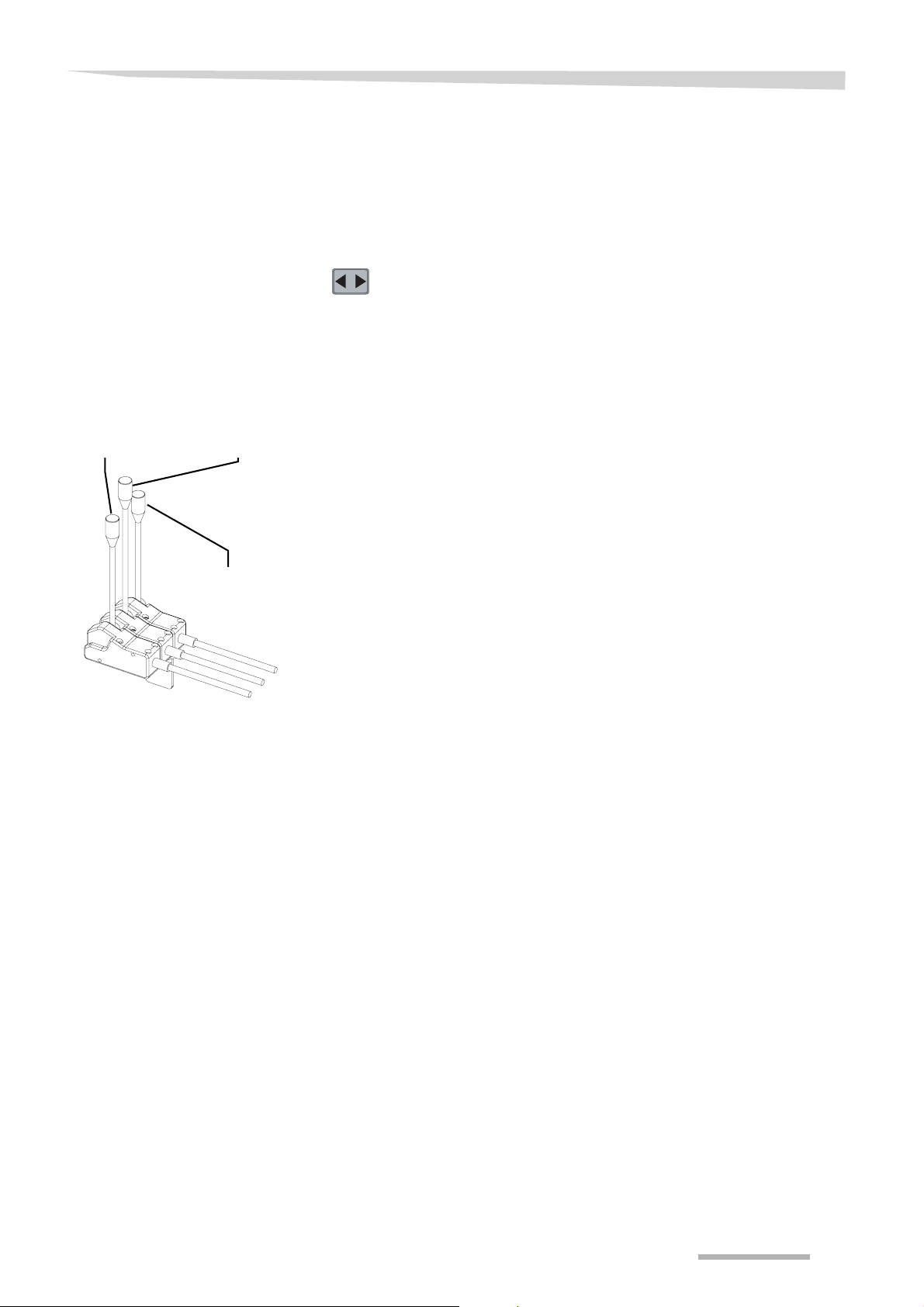
Cable control
Middle leverRight lever
Left lever
The loading arm and the table must be put into start position before
wrapping can get started.
The start position is reached when:
• the loading arm is in the middle position
• the table is fully downwards and in the loading position
> Push to reset the table revolution counter
The wrapping cycle depends on the kind of control on the machine:
• cable control
• electronic control
> Drive to the bale
> Move the right lever forwards to lift the bale using the loading arm
onto the table
> Move the right lever backwards to lower the loading arm complete-
ly
> Use the middle lever to start wrapping
The table must turn with maximum 30 rpm.
After the last but one number of film wraps, the buzzer sounds. Than
the final wrap is added.
Extra wraps can be added. The buzzer will sound 2 seconds for every
extra wrap.
> Leave the middle lever to stop wrapping
The bale counter will be reset to zero.
The table must be in tip off position now.
> Move the left lever backwards to unload the bale
> Move the left lever forwards to move the table into loading position
49
Page 50

Use at the field
Electronic control
The required number of film wraps must have been set
→ CYC, page 61
> Drive to the bale
> Use the hydraulic valve to lift the bale using the loading arm onto
the table
>Push
> Push activate the programm
> Push to operate the loading arm
> Push to start wrapping
In case the wrapping process is interrupted
> push to restart wrapping
The table must turn with about 30 rpm.
50
Page 51
Wrap and bale counter
Wrap and bale counter
General
Wrap and bale
counter box
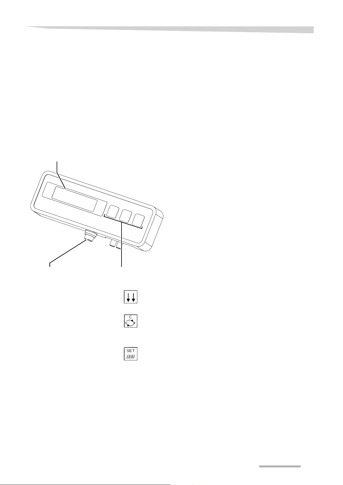
Control box front
Display
If the machine is equipped with a cable control, the wrap and bale
counter can be mounted. This counter controls and monitors the wrapping of the bale. Furthermore the buzzer sounds when the pre-set
number of wraps has been reached.
The wrap and bale counter box enables supervision of the bale wrapping procedure from the tractor cab. Especially the following functions
can be monitored:
• Bale counters (1 day counter, 1 total bale counter)
• Film wrap counter
Fuse Buttons
Buttons
Actual mode button
• Selection of the mentioned bale wrap sequence
Clear button
• Change a value
• Reset a value
Set button
• Change a value
51
Page 52

Wrap and bale counter
Parameter change
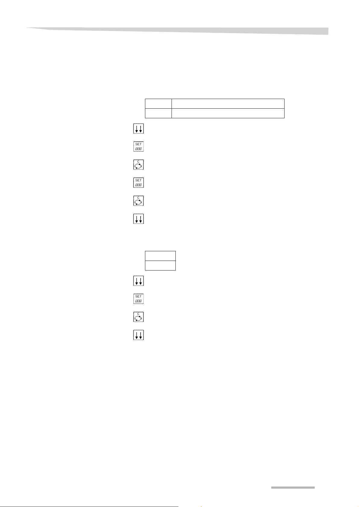
The parameters can be changed upon desire.
> Push to enter the desired display
> Push until the desired digit flashes
> Push to set the digit
> Push to confirm
52
Page 53
Wrap and bale counter
Parameter settings
CYK
Via the parameter settings, the entire wrapping process is prescribed.
The current number of table laps can be set. The pre-set number of
table laps can be shown in the display.
Number Recommended number
2 - 99 → Film wrap recommendations, page 48
> Push to enter the display CYK
> Push until the current number of table laps flashes
> Push to set the first digit
> Push for the last digit
> Push to set the last digit
> Push to confirm
BAL
The number of bales wrapped can be shown in the display. The number of bales wrapped can be reset to zero.
Number
0 - 99999
> Push to enter the display BAL
> Push until the number of bales wrapped flashes
> Push to reset to clear the number of bales wrapped to zero
> Push to confirm
53
Page 54

Wrap and bale counter
BAL +
F.
The total number of bales wrapped.
Number
0 - 99999
The total number of bales wrapped can not be reset
The stop position of the table can be set. Which gives the possibility
to leave the lever until the pre-set number of film wraps is reached.
Auto stop function must be set
Setting
0.00 -1.99
8 In case 0.00 is set: the table stops rotating immediately after reaching
the pre-set number of film wraps.
In case 1.00 is set: the table makes one turn after reaching the pre-set
number of film wraps.
> Push to enter the display F.
> Push until the first digit flashes
> Push to set the first digit
> Push until the second digit flashes
> Push to set the second digit
> Push until the last digit flashes
> Push to set the last digit
> Push to confirm
54
Page 55
Electronic control system
Electronic control system
General
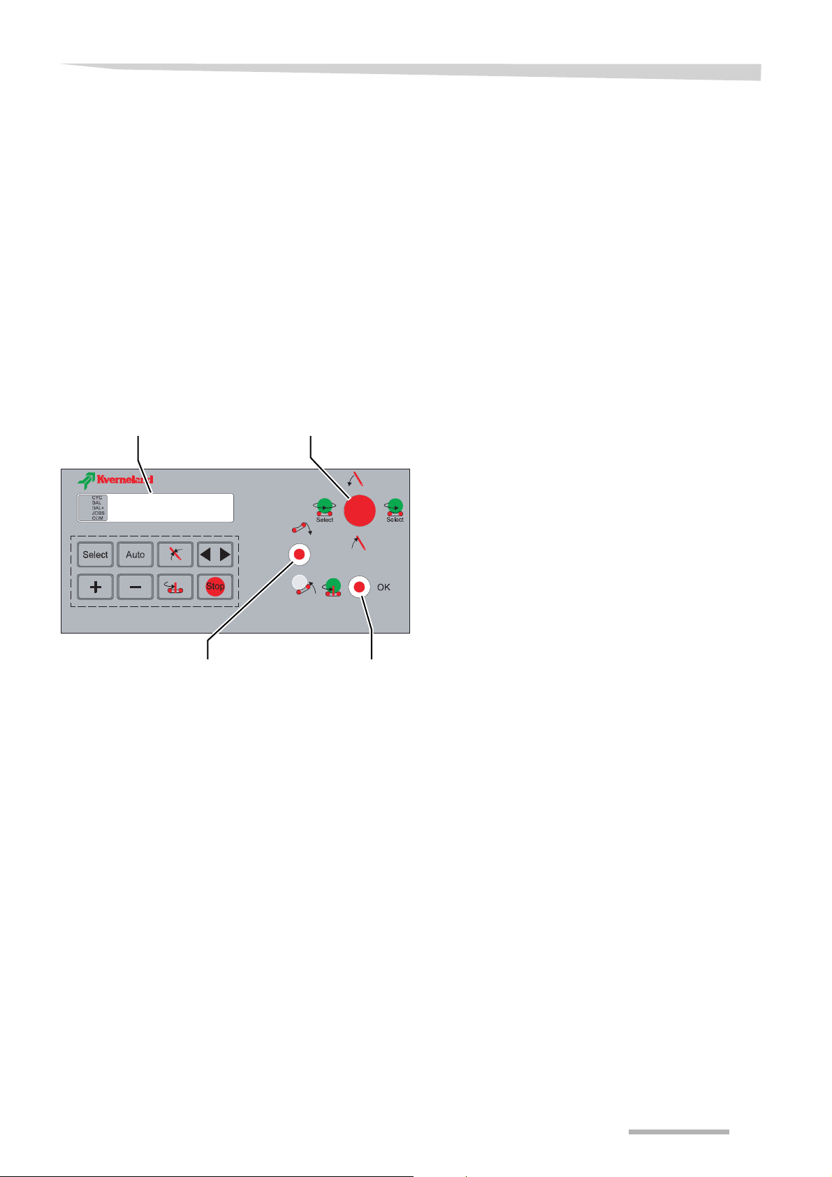
Control box
Control box front
Display
The machine can be equipped with an electronic control system. This
control system controls and monitors the wrapping and clearing out of
the bale. Furthermore the system also provides error indicating functions.
The control box enables supervision of the total bale wrapping procedure from the tractor cab. Especially the following functions can be
monitored:
• Bale counters (4 day counters, 1 total counter)
• Film wrapping process
• Automatic or manual film wrapping control
• Control of several individual parts of the machine
Joystick
Upper toggle
switch
Lower toggle
switch
55
Page 56
Electronic control system
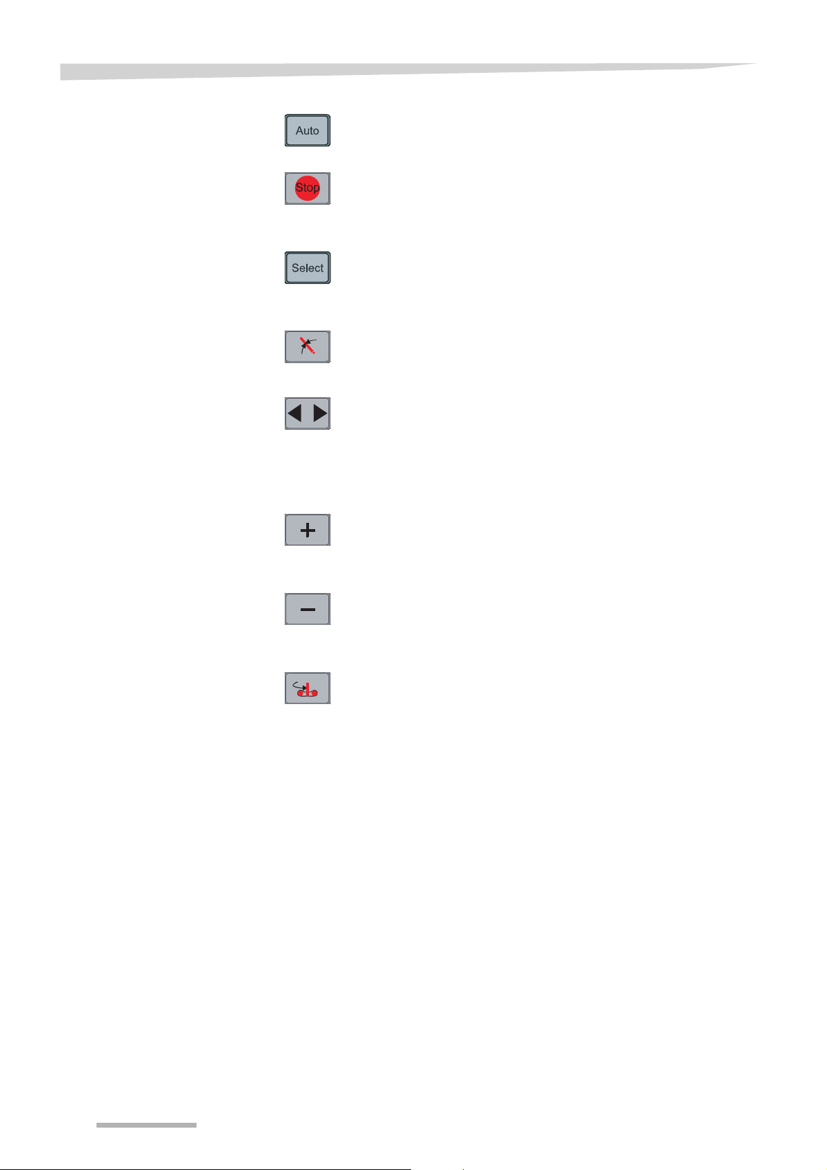
Buttons
Auto button
• Selection of automatic mode
Stop button
• To stop, interrupt a procedure. Rotation of the table is interrupted.
• Selection of manual mode
Programme mode button
• Programming functions
• Counter reset
To neutral position
The loading arm is moved to its neutral position, in front of its sensor.
To start point
To :
• move the loading arm to the middle position
• move the table fully downwards
• reset the revolution counter to zero
Pushing to
• increase a value
• switch the buzzer on
Pushing to
• decrease a value
• switch the buzzer off
Table to bale loading position
This is only possible, if the loading position sensor is mounted on the
machine.
56
Page 57
Electronic control system
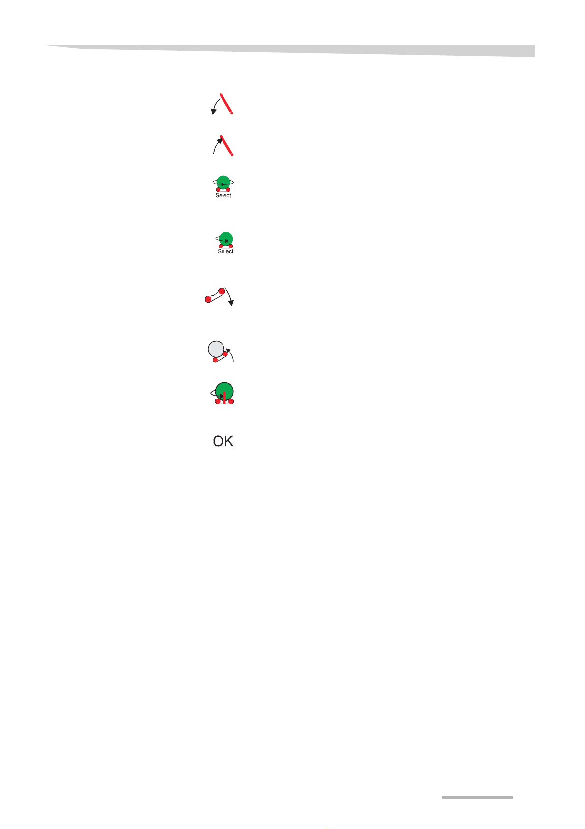
Joystick
Pushing up:
• lowering the loading arm
Pushing down:
• raising the loading arm
Pushing to the left:
• parameter selection
• table rotation at normal speed
Pushing to the right:
• parameter selection
• table rotation at low speed
Upper toggle switch
Pushing up:
• lowering the table
Pushing down:
• raising the table
Lower toggle switch
Pushing to the left:
• table to loading position
Pushing to the right:
• approve of a function
• interrupt the programm before the preset number of foil wraps has
been reached
• reset the revolution counter
57
Page 58

Electronic control system
Control mode
Manual mode
Semi-automatic
mode
The electronic control system can be used in the following control
modes:
• manual mode
• semi-automatic mode
• automatic mode
The set of parameters determines working in semi-automatic or automatic mode.
In manual mode, the wrapping cycle is controlled by the toggle switches and the joystick.
> Push to select manual mode
Depending on the requested action
> Push the concerning toggle switches or joystick on the control box
Semi-automatic mode offers the possibility for the following:
• to stop the table before film wrapping starts
• to stop before bale unloading
> Push to select semi-automatic mode
When one or more of the above-mentioned adjustments are selected,
the wrapping cycle will stop at the concerning point(s).
> Push to set the desired parameter
> Push to continue wrapping
58
Page 59

Electronic control system
Automatic mode
In automatic mode, the entire wrapping cycle is automatic.
> Push to select automatic mode
> Push to start wrapping
The machine starts in a programmed cycle.
In case of a failure or correction during wrapping
> Push to select manual mode
> Push to select automatic mode
>Push
Wrapping will continue from the point of failure.
59
Page 60

Electronic control system
Parameter change
The parameters can be changed upon desire.
>Push
> Push joystick left or right to select the desired parameter
> Push to change the parameter value
> Push to return to automatic mode
or
> Push to return to manual mode
The value is stored.
60
Page 61

Electronic control system
Parameter settings
CYC
BAL
BAL +
Via the parameter settings, the entire wrapping process is prescribed.
The number of table laps can be set.
Number Recommended number
1 - 100 no recommendation
The number of bales wrapped.
Number
0 - 99999
The number of bales can be reset
> Push to confirm
Now the total number of jobs increases with one.
→ JOBS, page 61
The total number of bales wrapped.
Number
0 - 99999
JOBS
The total number of bales wrapped can not be reset
The total number of jobs done.
Setting
0 - 99999 Can be cleared to zero
The total number of jobs can be reset to zero
> Push to confirm
After the number of bales has been cleared to zero, the total number
of jobs done increases with one.
61
Page 62

Electronic control system
A. on / A. off
A1:1 / A1:0
A2:1 / A2:0
A buzzer can be switched on or off for
• a sound after the last sensor by-pass
• when an error occurs
Setting Buzzer
• +
• -
This setting is only valid in case your machine is equipped with the
electronic control system.
The bale loading with the loading arm can be included in the wrapping
procedure.
Setting Recommended setting
• 1 = yes
• on
• off
1
• 0 = no
This setting is only valid in case your machine is equipped with the
electronic control system.
The start of film wrapping after bale loading.
Setting Recommended setting
• 1 = start
1
• 0 = stop
After the bale is loaded
> Push to confirm
62
Page 63

Electronic control system
A3:1 / A3:0
A4:1 / A4:0
A6:1 / A6:0
The bale unloading can be included in the wrapping procedure.
Setting Recommended setting
• 1 = yes
1
• 0 = no
If ‘0’ is chosen, a new loading and wrapping cycle can be started
> Push to confirm
The bale unloading can be done immediately after the wrapping cycle
is finished.
Setting Recommended setting
• 1 = yes
0
• 0 = no
If ‘0’ is chosen, the bale unloading can be done manually
> Push to confirm
This setting is only valid in case your machine is equipped with the
loading position sensor.
After bale unloading the table turns 90°.
A7:1 / A7:0
Setting Recommended setting
• 1 = possible
1
• 0 = impossible
Independent on an optional film sensor is mounted, this setting must
be used.
Setting Recommended setting
• 1 = mounted
0
• 0 = not mounted
63
Page 64

Electronic control system
t1
t2
t3
Start of the flashing light before the automatic wrapping cycle starts.
It is recommended to mount a flashing light when a remote control is
mounted.
Flashing light Setting Recommended setting
• mounted
• not mounted
The time can be set before an error message occurs, in case a sensor
does not function.
Setting Recommended setting
sec 15
This setting is only valid in case your machine is equipped with the
electronic control system.
The maximum raising time for the loading arm from the middle position
to the fully lifted position.
Setting Recommended setting
sec 4 - 6
• sec and 1/10 sec
• sec and 1/10 sec
• 2.0
• 0.0
t4
t5
t6
This setting is only valid in case your machine is equipped with the
electronic control system.
The time delay for lowering the loading arm after reaching the sensor.
Setting Recommended setting
sec and 1/10 sec 0.5
Before the table rotates at normal speed, a slow-motion start time can
be set.
Setting Recommended setting
sec and 1/10 sec 2.5
After the last sensor by-pass, the table speed can be delayed slow
down.
Setting Recommended setting
sec and 1/10 sec 1.0 - 2.0
64
Page 65

Electronic control system
t7
t8
t9
t10
The time the table turns at half speed before stopping, after the last
sensor by-pass t6 has taken place.
Setting Recommended setting
sec and 1/10 sec 1.5 - 2.5
The time the table is standing still before turning at half speed to the
bale unloading position, after the table has stopped.
Setting Recommended setting
sec and 1/10 sec 0.5 - 0.7
The table raising time before bale unloading.
Setting Recommended setting
sec 4 - 6
The time delay before lowering the table.
Setting Recommended setting
sec and 1/10 sec 0.3 - 0.5
t11
t12
t14
The time delay after the table is fully lowered.
Setting Recommended setting
sec and 1/10 sec 0.3 - 0.5
Not in use.
The maximum interval between the pulses of the film sensor when
wrapping in automatic mode.
Setting Recommended setting
sec and 1/10 sec 1.0
> Push to confirm
65
Page 66

Cleaning and caring
Cleaning and caring
Safety
Cleaning
Pre-stretcher rollers
For all cleaning and caring activities applies:
Do not penetrate bearings and hydraulic parts
Be careful when cleaning with a high-pressure cleaner. Bearings,
sealings and bolted joints are not waterproof. To avoid machine damages never penetrate bearings, sealings and bolted joints with water.
Do not clean bearings and hydraulic parts with high pressure
Do not clean bearings and hydraulic parts with a high-pressure cleaner. Bright metal parts will get degreased and start rusting. After every
cleaning grease the bearings and grease bright metal parts.
After every time of using the machine:
> Empty and clean the machine of all accumulated crop
Cleaning can be done with low pressure with the high-pressure cleaner. Do not clean bearings, electronic and hydraulic parts with the highpressure cleaner.
The pre-stretcher rollers must be cleaned from particles, dust, crop
and tack.
> Use methylated spirit or similar to clean the rollers
After cleaning
Caring
After cleaning with the high-pressure cleaner
> grease all bearings
When you observe the rules below, you will have a fully operational
machine at the start of the next season:
> Protect all bright metal parts with an oil film. Only use authorized
biological oil, like rape oil
> Repaint any paint damages
66
Page 67
Storing the machine
Storing the machine
Safety
Unhitching and securing of the machine
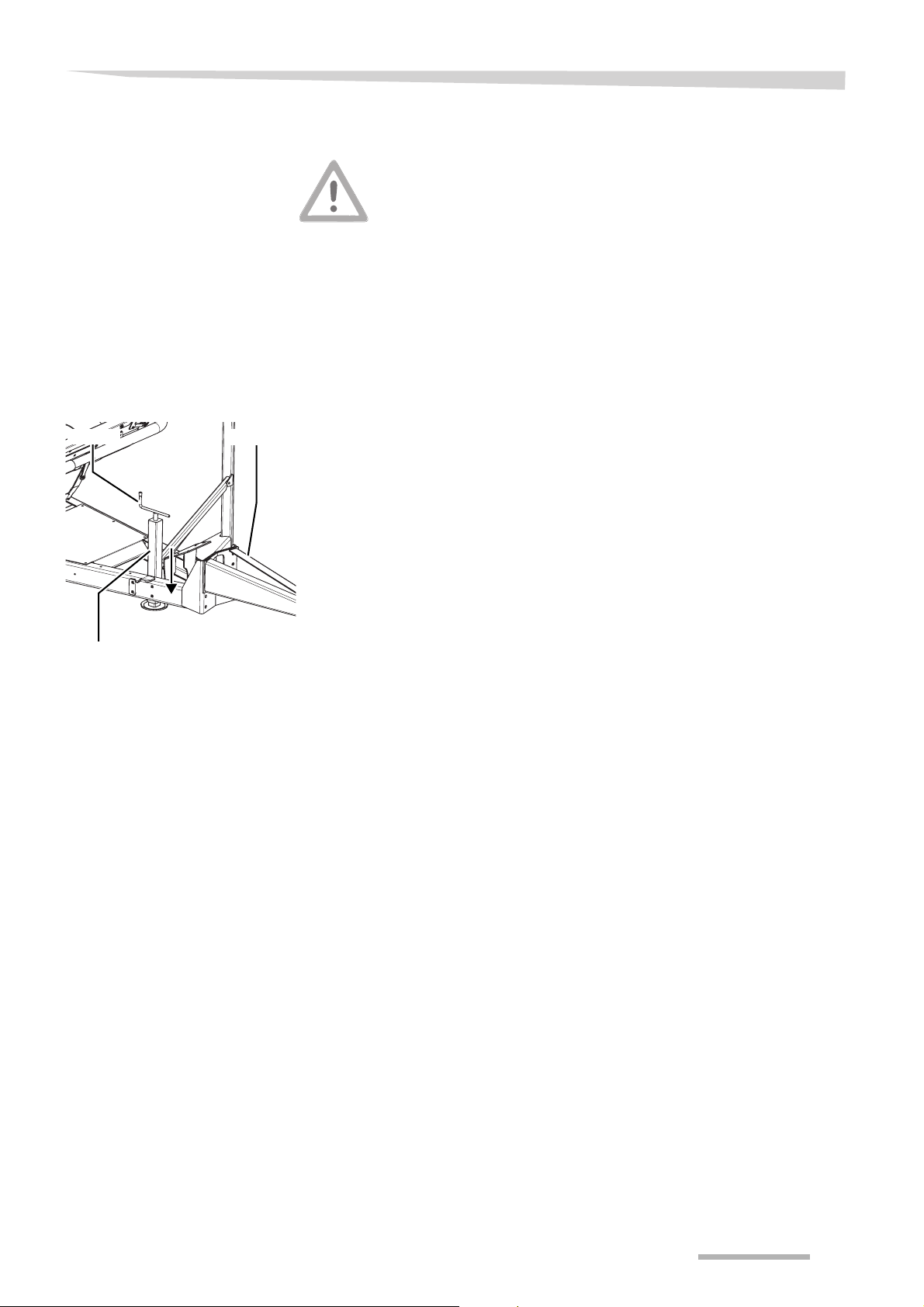
DrawbarHandle
Obey the safety instructions
Obey the safety instructions at the execution of all work. Ignoring the
safety information can lead to serious or deadly injuries.
Machine is no toy
Store the machine in an area away from human activity. Never allow
children to play on or around the stored machine. Metal edges and
parts of the machine can lead to serious injuries.
> Place the machine on a dry and stable ground
> Secure the tractor from rolling away
> Disconnect the hydraulic connections and store them in the sup-
port at the drawbar
> Disconnect the electronic connections and store them in the sup-
port at the drawbar
> Use the handle to lower the support jack fully
Machine with electronic control box only
> Store the control box in a dry and dust-proof room free from ro-
dents, insects and martens
Support
jack
After the season
> Unhitch the machine from the towing hook of the tractor
After the season and at longer storage periods, the following work
must be performed:
• Thoroughly clean the machine
→ Cleaning, page 66
• Check all bolted joints and torque them
• Repair or replace damaged parts
• Repaint any paint damages
• Lubricate the machine
• Check the tyre pressure
67
Page 68

Maintenance
Maintenance
Safety
For all maintenance work applies:
Take care of the safety instructions
Definitely take care of the safety instructions during all work. In case
of negligence of the safety instructions serious or deadly accidents
can occur.
Conditions for maintenance work
Only carry out maintenance work if you do dispose of the necessary
professional knowledge and of the suitable tools. Missing professional
knowledge or unsuitable tools can cause accidents or damages.
Use original parts
Use original parts for safety relevant components. Dimensions,
strength, and material quality must be guaranteed. Building in of not
original parts reduces the warranty to nil and void.
Protect the machine against unintentional use
Carry out general repairs, maintenance and repair of function troubles
at the hitched machine, in principle with switched off hydraulics,
switched off engine and removed ignition key! At unintended taking into use serious accidents can be caused.
Welding work
Before welding work at the tractor and the machine in principal the
electronic circuit must be interrupted. Otherwise damages to the electronic can not be excluded.
68
Page 69

Maintenance
Protection measures
in contact with oil or
lubricants
Additives in oil and lubricants can have, under circumstances, harmful
effects to health. Because an indication according to the danger order
is not necessary, therefore in principle please pay attention to:
Avoid skin contact
Avoid skin contact with these oil and lubricants. Protect your skin by
skin protection creams or oil-resistant gloves. Skin contact can lead to
skin diseases.
Do not use oil for cleaning
Never use oil and lubricants for hand cleaning! Chips and waste in this
oil and lubricants can extra lead to injuries.
Change dirty clothing
Change extremely filthy oiled clothing as soon as possible. Oil can
cause health injuries.
T
IP
• Waste oil must be collected and recycled
• in case skin diseases by oil or lubricants occur, immediately visit a
doctor
69
Page 70

Maintenance
General
Information of directions
Direction Description
Left counterclockwards
Right clockwards
Front in the direction of travel
Rear in the direction of travel
Rotation around a horizontal axis as seen at right angles to the direction of travel from left to right
Rotation around a vertical axis as seen from top to bottom
Rotation from bolts, nuts, etcetera always as seen from the operating side
This information is related to all maintenance work. At all maintenance
work the machine must be secured in working position. In case the
transport position is necessary for maintenance, you will find suitable
tips to the maintenance work.
Information of directions (left, right, front, rear, above, below) are to be
seen in the direction of travel.
The directions have been defined as follows:
70
Page 71
Maintenance
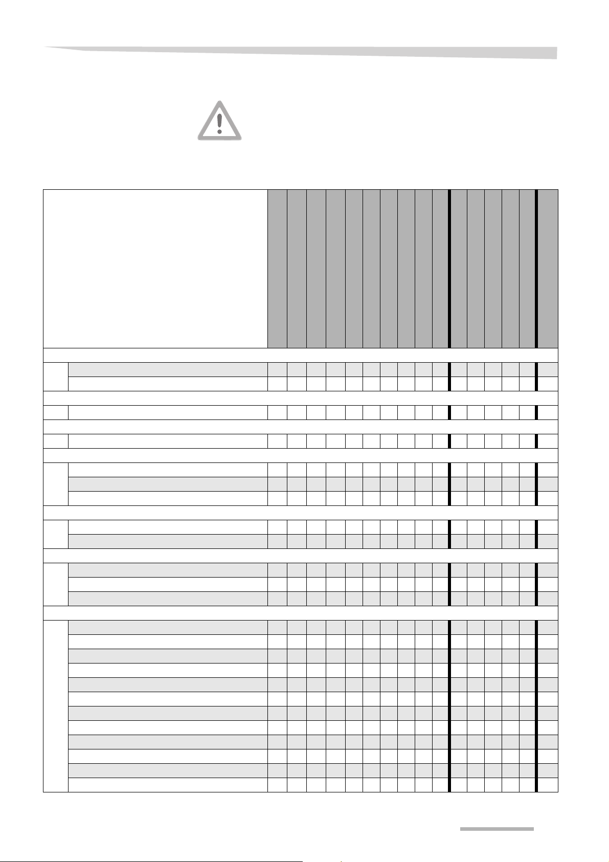
Maintenance intervals
Before doing any maintenance, the following must be obtained:
• Clean the machine before doing any repair work
• Never work on the machine while it is running
• The tractor engine must be switched off and the ignition key must
be removed
• Clean the machine with a compressor
Oil
Grease
Every week
Once per season
Every 10 working hours
Every 15 working hours
Every 50 working hours
Every 150 working hours
After the first working hour
After the first 8 working hours
After the first 50 working hours
Attaching elements
Screwing bolts tighter
Special torques
Pre-stretcher
Checking the pre-stretcher rollers
Wheels/tyres
Tyre pressure
Hydraulics
Hydraulic hoses 76
Filter hydraulic block
Filter hydraulic block
Table
Drive chain tension
Table lock adjustment 77
Applicutter
Applicutter knife replacement
Catch rod adjustment 78
Cutting time adjustment 79
Lubrication
Motor gear
Gear ring
Table roller drive chain
Table sprocket
Tipping frame hinges
Loading arm hinge
Loading arm cylinder
Wheel hubs
Wheel arm right
Applicutter
Catch rod applicutter
Pre-stretcher gears
• • • • •
•• • ••
••••
•••
• •
• • •
••
• •
••
••
• •
••
• •
••
Every 200 working hours
• •
••
••
••
• •
Check
Tighten
Change
•
Page
72
72
74
75
76
76
77
78
80
80
80
81
81
81
81
82
82
82
82
83
71
Page 72
Maintenance
Attaching elements
Screwing bolts
tighter
Special torques
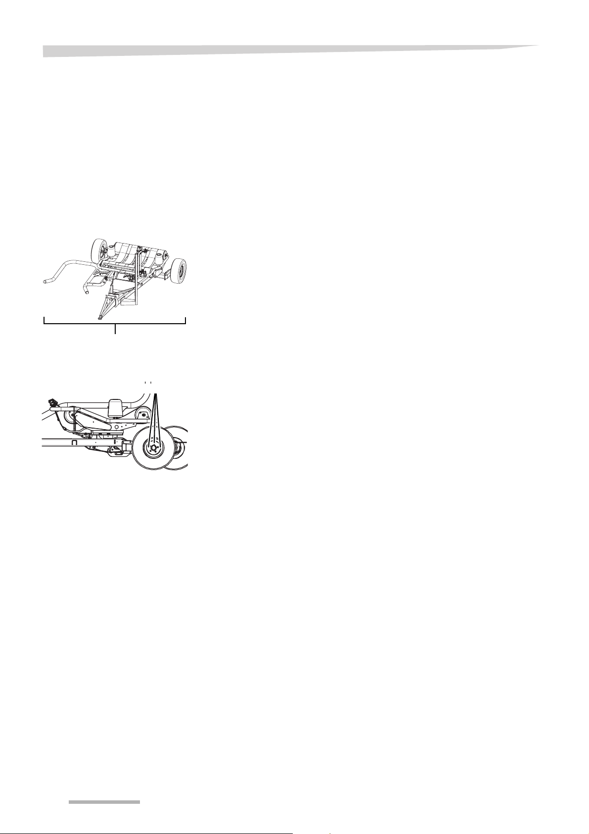
220 Nm
220 Nm
All bolts and nuts must be checked and screwed tighter:
• after the first 8 working hours
• depending on the usage frequency of the machine
• at least once per season
Take care of the special torques for the following screwed joints:
• 220 Nm all main frame bolts
All main frame bolts must be checked and screwed tighter:
• after one working hour
• every week
• 220 Nm wheel nuts
Check and screw tighter the wheel nuts:
• after the first 8 working hours
• every week
• after every tyre / wheel renewal
72
Page 73
Maintenance
Tightening
torques
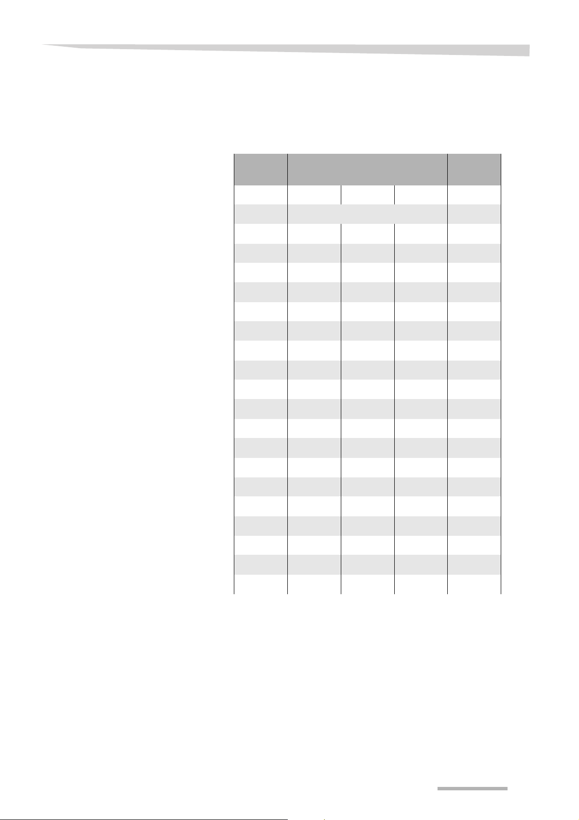
All screwed joints on this machine must be torqued in accordance with
the values given in this table below unless indicated otherwise.
On this machine, 8.8 is both standard and minimum quality used. If not
indicated anyhow use this quality for determination of torque (in most
cases the quality can be found on the head of the respective bolt).
Thread Torque value Spanner
size*
8.8 10.9 12.9
Nm mm
M3 1.3 1.8 2.1 6
M4 2.9 4.1 1.9 7
M5 5.7 8.1 9.7 8
M6 9.9 14 17 10
M8 24 34 41 13
M10 48 68 81 17 (15)
M12 85 120 145 19 (17)
M14 135 190 225 22 (19)
M16 210 290 350 24 (22)
M18 290 400 480 27
M20 400 570 680 30
M20 x 1.5 - 640 - 30
M22 550 770 920 32
M24 700 980 11 80 36
M27 1040 1460 1750 41
M30 1410 1980 2350 46
M33 1910 2700 3200 50
M36 2450 2546 3063 55
M39 3200 4500 5400 60
* Values in brackets = spanner size of lock bolts and nuts with toothed
flange are given in brackets if different from standard.
T
IP
• The listed values are applicable for dry or slightly oiled joints
• Do not use plated bolts/screws/nuts without grease
• When a stiff grease is applied decrease the given value by 10%
• In case lock nuts, lock screws or lock bolts are used increase the
given value by 10%
73
Page 74
Maintenance
Pre-stretcher
Checking the prestretcher rollers
Pre-stretcher
rollers
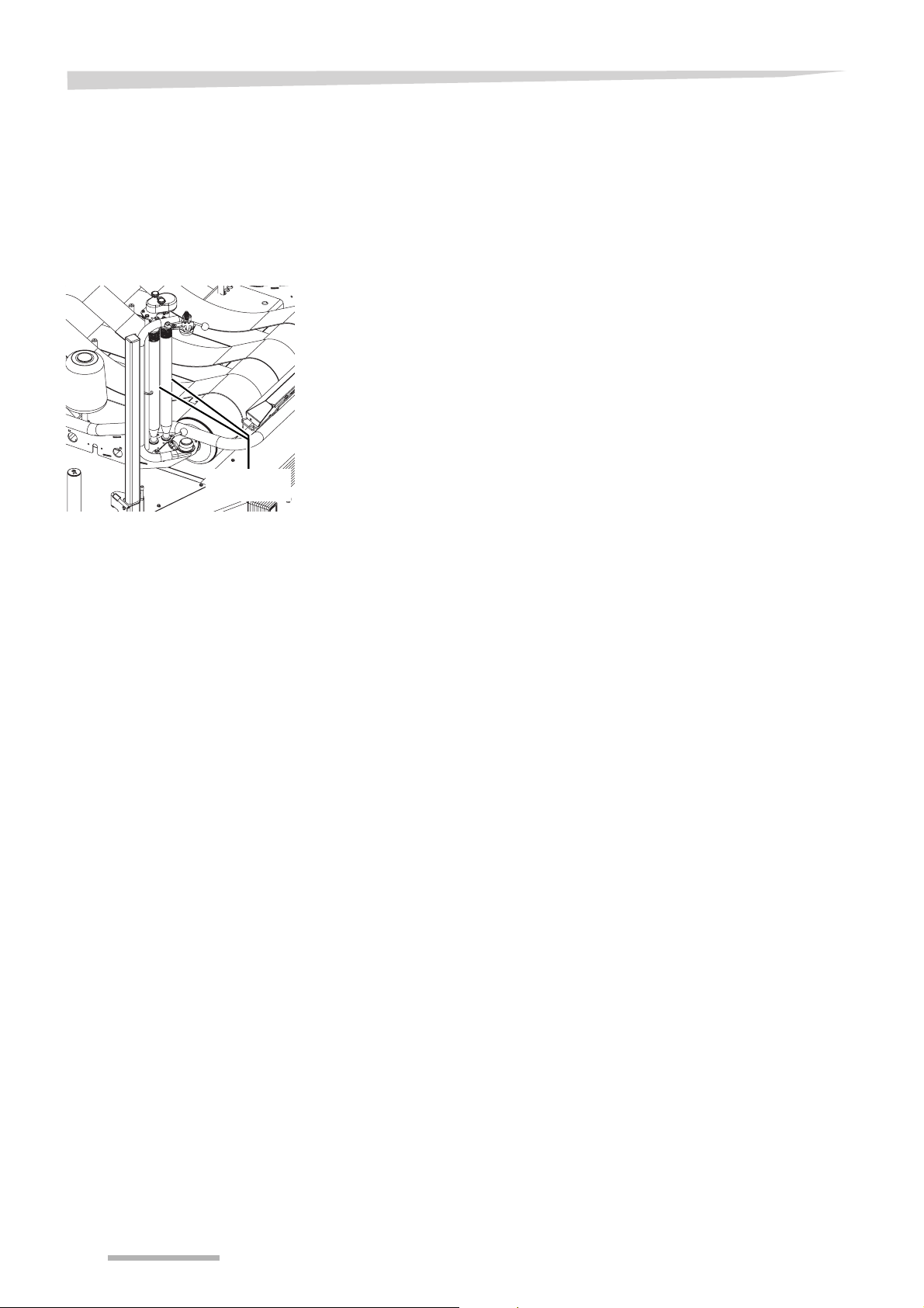
The pre-stretcher must be checked
• after the first 50 working hours
• after every 500 working hours
> Check that the bolts of the rollers gears are tightened correctly
> Check that the pre-stretcher rollers can be moved by hand easily
> Check that the pre-stretcher rollers are clean
74
Page 75

Maintenance
Wheels/tyres
Do not drive with worn-out or damaged tyres
Exchange worn-out or damaged tyres immediately. Especially during
road transport with such tyres an increased risk of accidents exists.
Correct repairwork only
Repairwork on wheels and tyres must only be carried out
• by professionals
• with the correct fitting equipment
Mounting wheels and tyres requires sufficient knowledge and availability of prescribed tools and equipment being in perfect condition.
Serious personal injuries or machine damages can occur.
Tyre dimensions as prescribed
Do not fit other tyre dimensions than prescribed. Fitting other tyre dimensions can cause accidents. Personal injuries or machine damages can occur.
Prescribed tyre pressure only
Only use the prescribed tyre pressure. Using the wrong tyres pressure
can cause serious personal injuries, machine damages or traffic accidents.
When working on the wheels and tyres make sure that the machine
• has been placed on the ground safely (use support jack)
• is secured by chocks against unintentional rolling
Tyre pressure
Check the tyre pressure regularly
• once a day
• before every road transport
• before and after every season
Tyre size Tyre pressure (bar)
11.0/65-12 2.3
75
Page 76
Maintenance
Hydraulics
Hydraulic hoses
Filter hydraulic block
Indicator
Take care at welding work
Do not carry out welding work near to hydraulic hoses. Hydraulic oil
can ignite very easily.
Hydraulic device pressureless
Before replacing the hydraulic hoses, the hydraulic device must be
pressureless. When working at a hydraulic device which is under pressure, by unintentional movements at the machine or by squirting hydraulic oil, accidents can occur.
Hydraulic hoses age without recognizable external indications, too.
Therefore, we recommend to replace the hydraulic hoses every six
years.
> Make the hydraulic device pressureless
> Switch off the engine and remove the ignition key
> Discouple the hydraulic hoses
> Replace the hydraulic hoses
Stay clear of the table area
Stay clear of the table area while it is rotating. Serious injuries can occur.
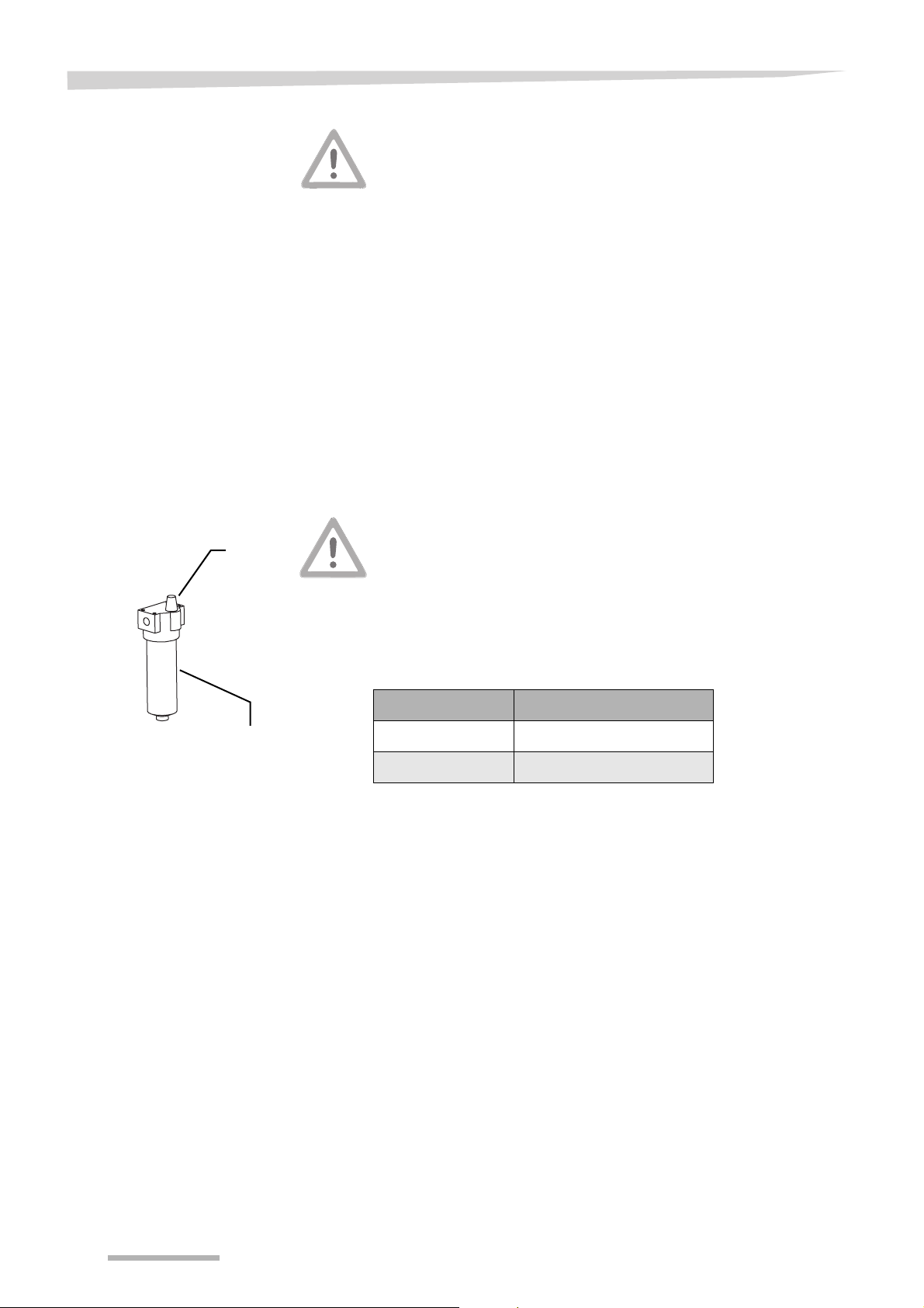
Filter
The filter is situated near the hydraulic block of machines with control
box only.
The filter contains an indicator on top of it. The indicator shows, whether the filter has to be exchanged or not.
Indicator colour Meaning
green The filter is clean
red The filter must be replaced
Only check the indicator when the hydraulic oil is at working temperature.
When the machine is hitched onto a tractor with a closed centre hydraulic system, the tractor engine must be at the rpm as during wrapping before checking the filter indicator.
> Check the indicator every 3000 bales or once a season
> Replace the filter every 8000 bales and once a season
76
Page 77
Table
Maintenance
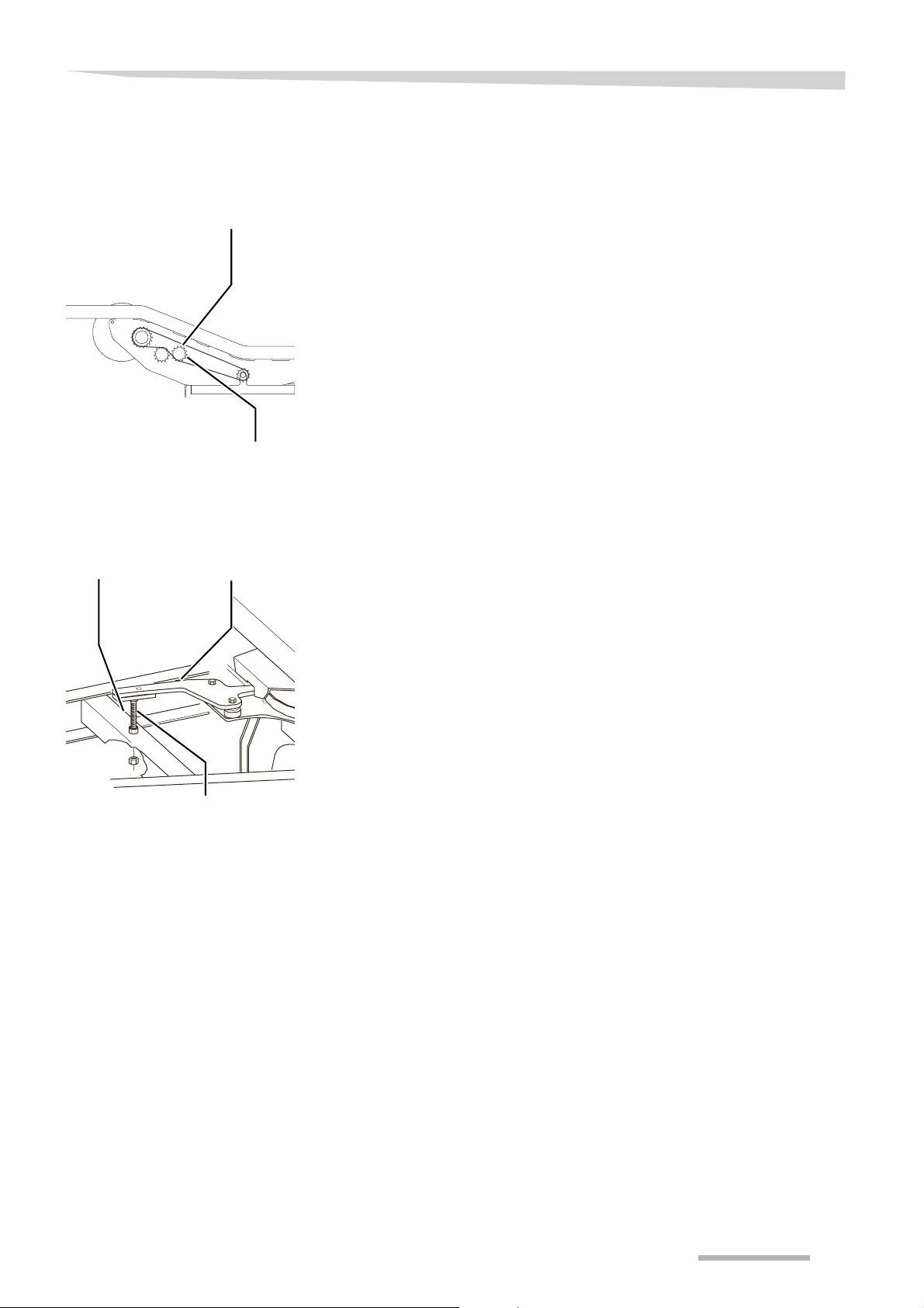
Drive chain tension
Chain tensioner
Lock nut
Table lock adjustment
Frame
Table lock
The table roller drive chain is under the cover, at the side of the table.
The chain should have a slight slack.
> Check the chain tension every week
Correct the chain tension as follows:
> Loosen the lock nut
> Move the chain tensioner to the left or to the right until the chain is
tensioned correctly
> Tighten the lock nut
The table lock prevents the table from turning in the wrong direction.
When the table is fully down, the length of the bolt must be adjusted
so that the table lock
• is open when the table rotates to the left
• is closed when the table rotates to the right
Bolt
The table lock must be adjusted if it does not work correctly.
> Turn the bolt to the left or to the right until it touches the frame
77
Page 78
Maintenance
Applicutter
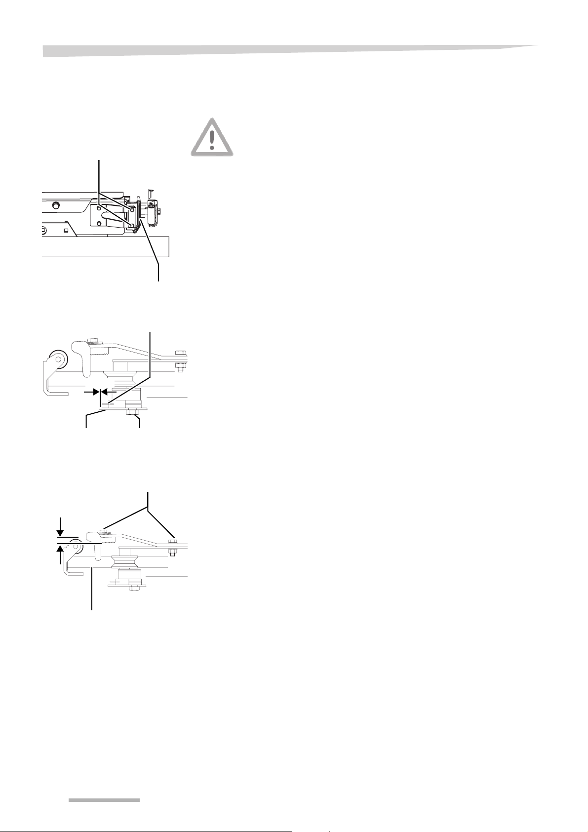
Applicutter knife replacement
Bolts
Applicutter knife
Applicutter knife
2 mm
Wear safety gloves
The applicutter knife is very sharp. Always wear safety gloves when
handling the applicutter knife. Not wearing safety gloves can cause
serious injuries.
In case of a dull applicutter knife, it can be exchanged.
> Switch off the electronic control system
> Shut down the tractor engine
> Remove the ignition key
> Loosen the bolts
> Take out the dull applicutter knife
> Place a new applicutter knife
The applicutter knife must be adjusted:
• parallel to the edge of the cover
• 2 mm from the edge of the cover
> Tighten the bolts
Cover Bolts
Catch rod adjustment
Bolts
C
Catch rod
The catch rod must have a distance C of 4 - 5 mm between the
wheels. If the film is slipping out the catch rod after cutting, distance C
must be checked and adjusted if necessary.
> Use washers below the bolts to increase distance C
> Remove washers below the bolts to decrease distance C
78
Page 79
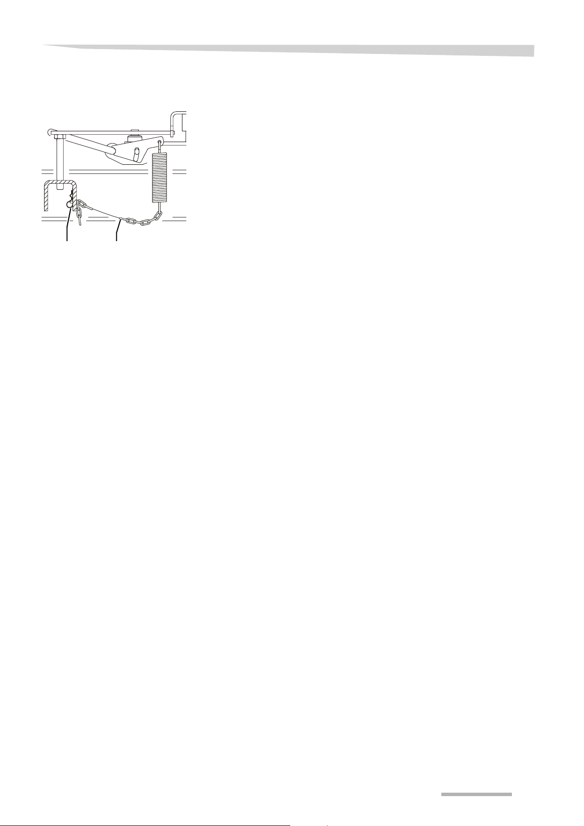
Maintenance
Cutting time adjustment
ChainSpring clip
The length of the chain must be adjusted so that the film is cut when
it is fully collected by the catch rod.
> Remove the spring clip
> Adjust the chain to the desired length
> Mount the spring clip
79
Page 80
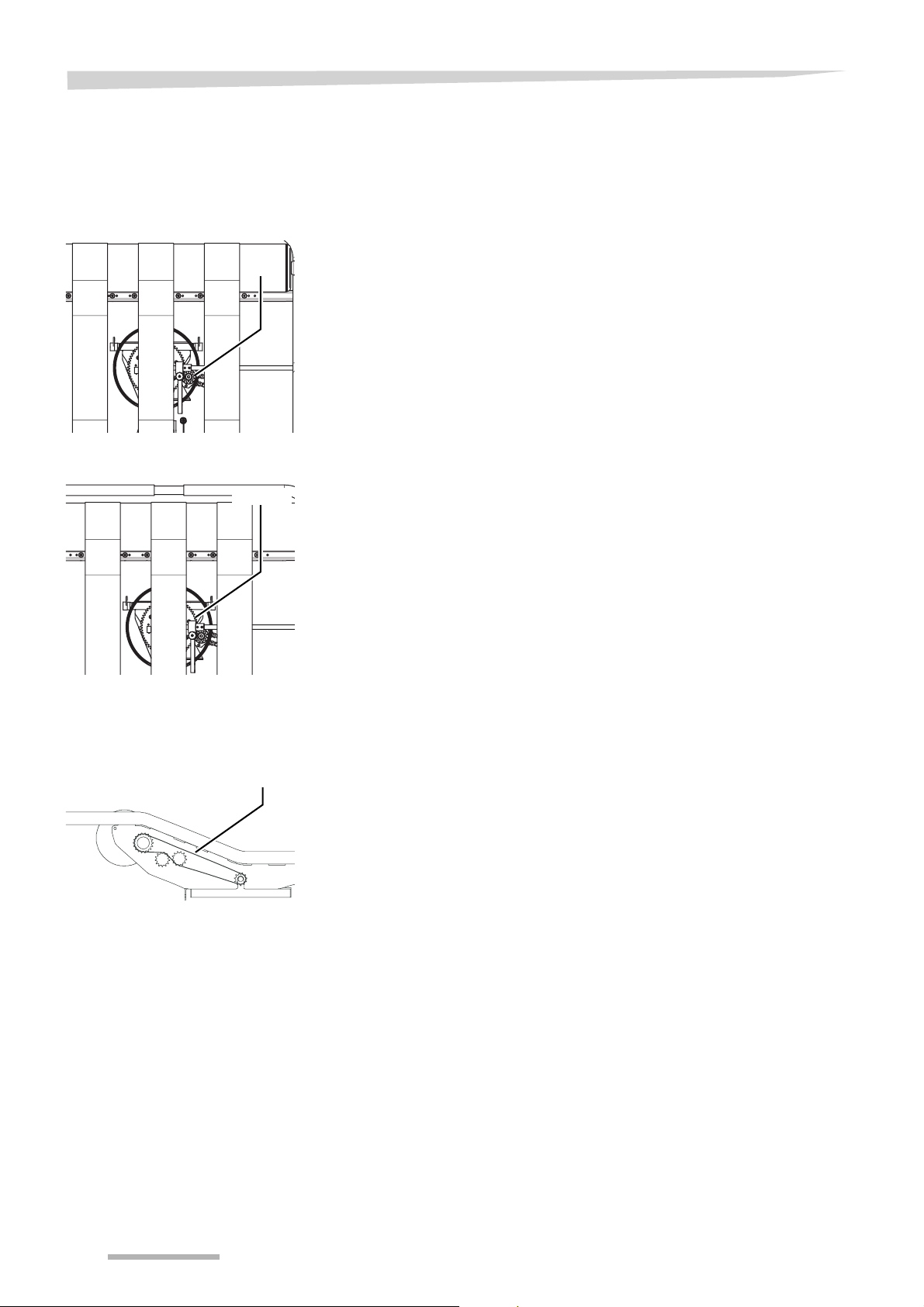
Maintenance
Lubrication
Motor gear
Gear ring
Motor
gear
Gear ring
All grease nipples must be greased
• after every cleaning with a high-pressure cleaner
• every indicated working hours indication
> Clean the motor gear if necessary
> Grease the motor gear every 10 working hours
> Clean the gear ring if necessary
> Grease the gear ring every 200 working hours
Table roller drive
chain
Drive
chain
> Oil the table roller drive chain every 50 working hours
80
Page 81
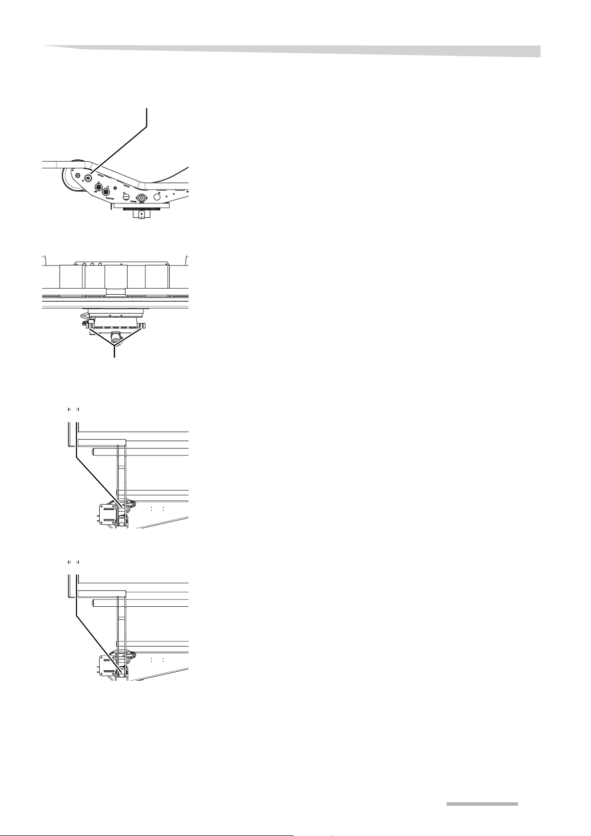
Table sprocket
Grease nipple
Tipping frame hinges
Maintenance
> Grease the grease nipple every 50 working hours
> Grease the grease nipples on both sides every 50 working hours
Grease nipples
Loading arm hinge
Grease nipple
Loading arm cylinder
Grease nipple
> Grease the grease nipple every 15 working hours
> Grease the grease nipple every 150 working hours
81
Page 82
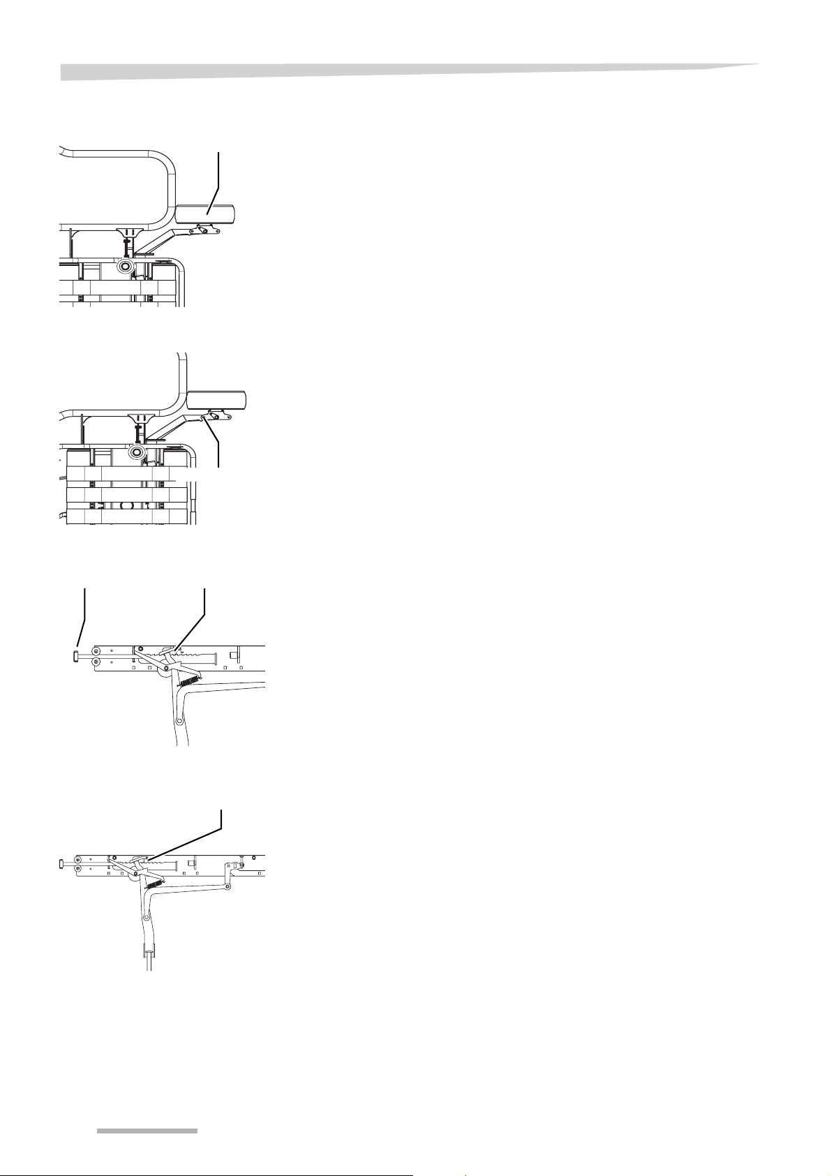
Maintenance
Wheel hubs
Grease nipple
Wheel arm right
> Grease the grease nipple on both left and right wheel hub every 50
working hours
> Grease the grease nipple every 50 working hours
Grease nipple
Applicutter
Roller Pawl bar
Catch rod applicutter
Catch rod
> Grease the pawl bar every 50 working hours
> Oil the roller every 10 working hours
> Grease the catch rod every 50 working hours
82
Page 83
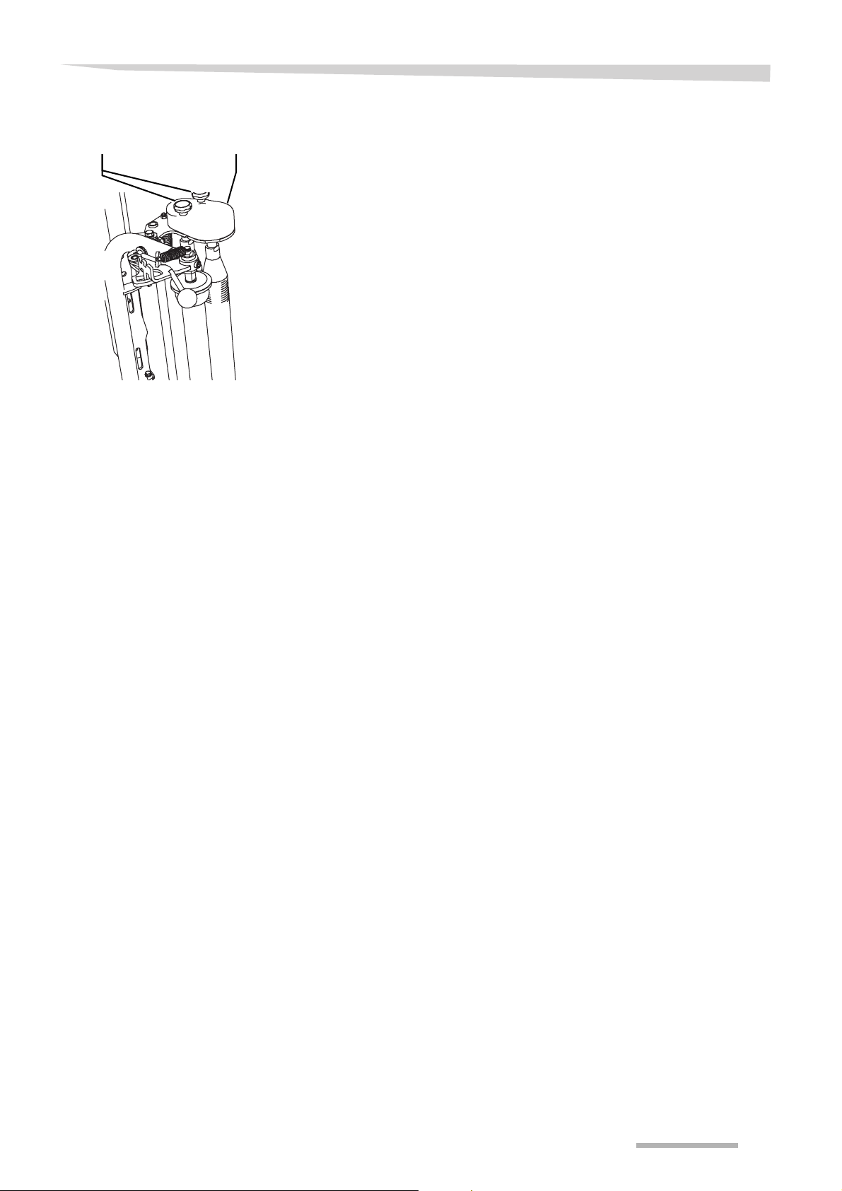
Maintenance
Pre-stretcher gears
CoverKnurled knobs
The pre-stretcher gears are situated under the cover.
> Remove the knurled knobs
> Open the cover
> Oil the pre-stretcher gears every 50 working hours
> Close the cover
> Mount the knurled knobs
83
Page 84
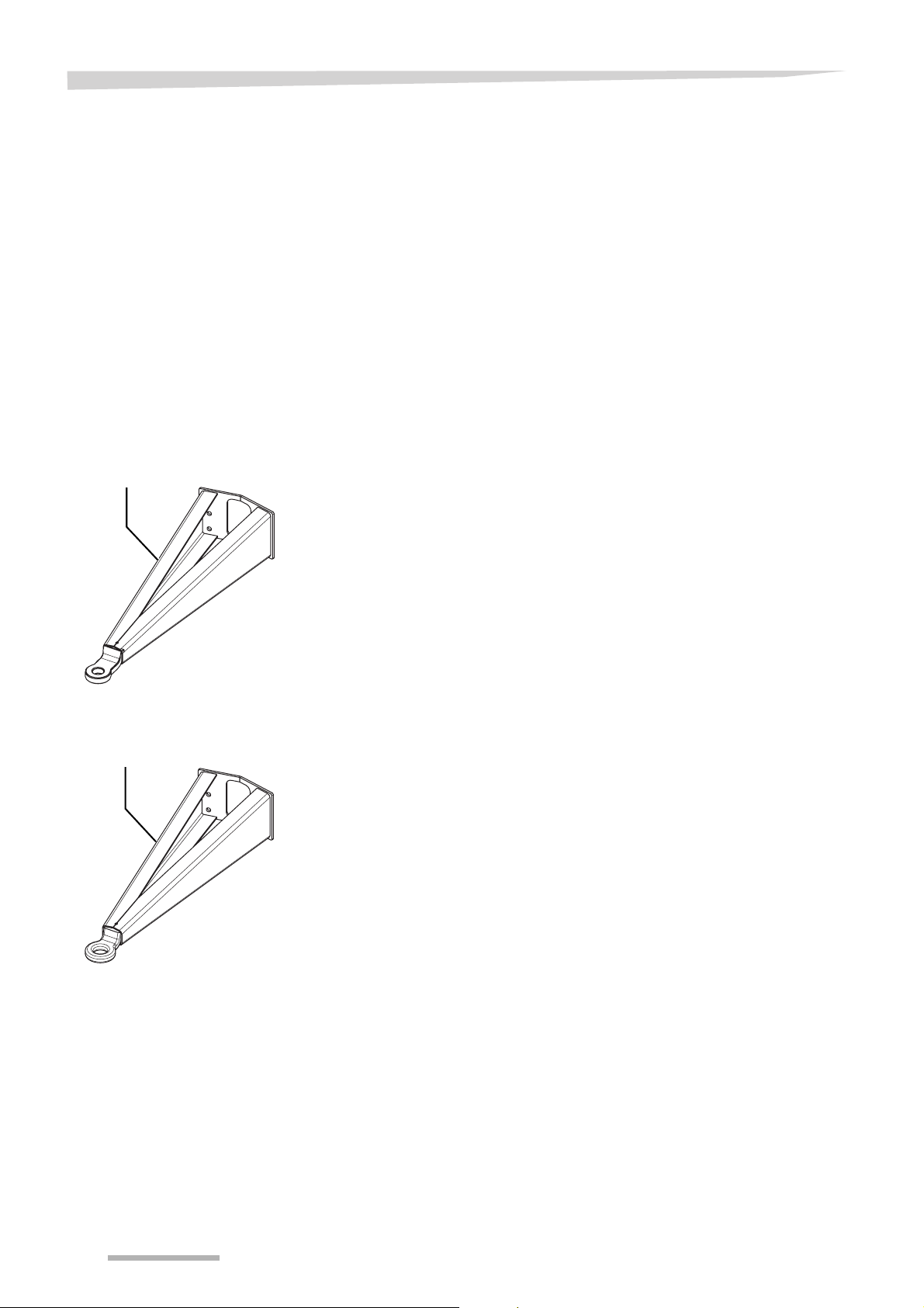
Optional equipment
Optional equipment
General
Standard drawbar
Standard drawbar
Where parts are to be changed, only use genuine original spare parts.
When ordering, quote the machine identification numbers. Trained
people only must carry out the use, maintenance and repair of the machine. Consult your dealer for any additional advice.
In addition, the warranty will be automatically annulled if the machine
has been equipped with accessories or spare parts not authorised by
the manufacturer.
Optional equipment may only be mounted
• in accordance with the mounting instructions
• to the appropriate attaching points
For details of the optional equipment
→ Spare parts manual
Drawbar with eye
Drawbar with eye
84
Page 85
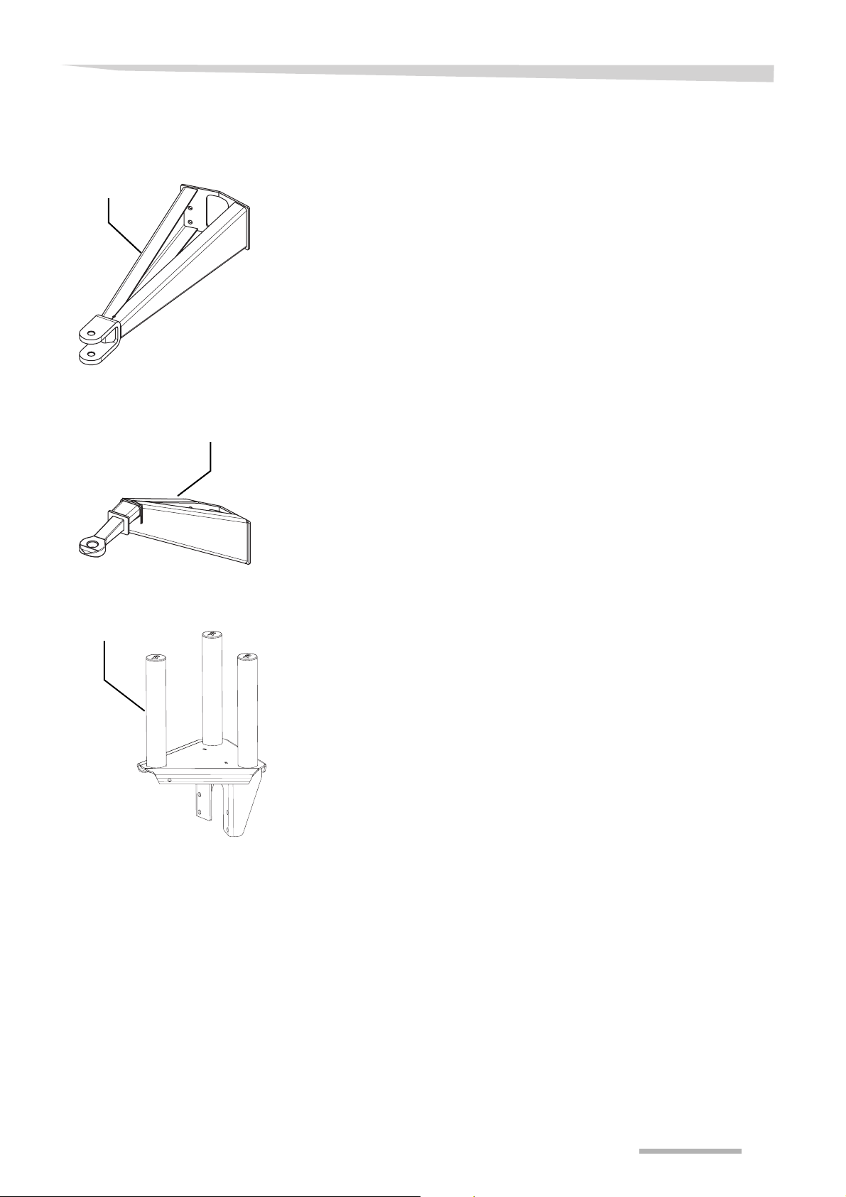
Drawbar with double tongue
Drawbar with
double tongue
High drawbar
High drawbar
Optional equipment
Film roll holder
Film roll holder
This film roll holder offers the possibility to carry 3 additional film rolls.
85
Page 86
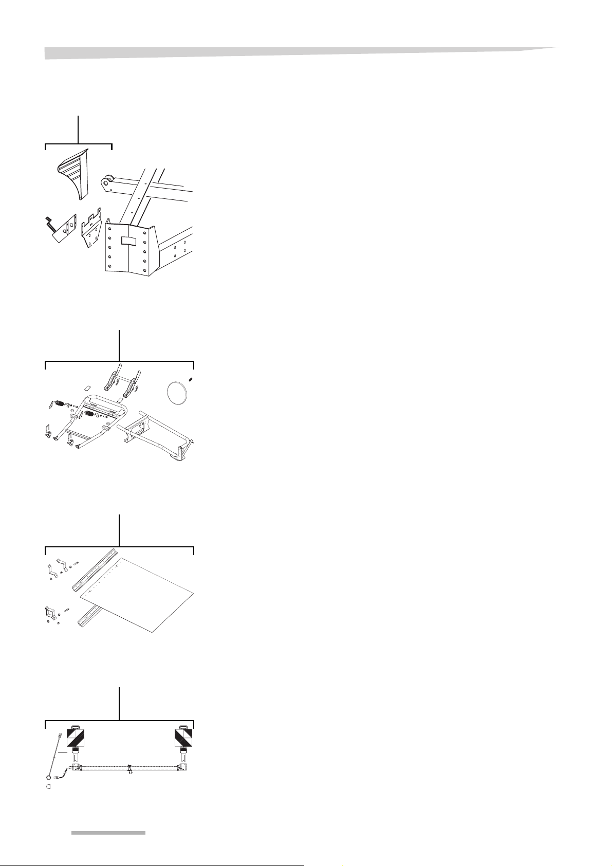
Optional equipment
Wheel chock set
Wheel chock set
Bale turner
Bale turner set
Drop mat
Drop mat
To prevent wrapped bales from rolling away, the bale turner is used to
place the wrapped bales on their flat side.
The drop mat is used to prevent punctures on the bale from stiff stubble when unloading the bale on the ground.
Road lighting
Road lighting set
86
Page 87
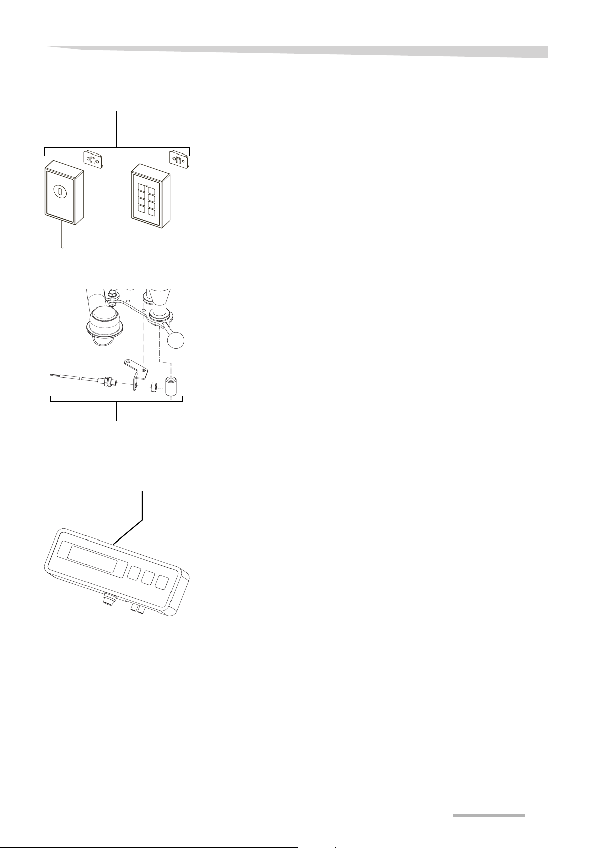
Remote control
Remote control
Film break set
Optional equipment
Film break set
Bale counter
Bale counter
87
Page 88

Troubleshooting
Troubleshooting
Safety
Switch off engine
Before any resolving of troubles:
> switch off the engine and remove the ignition key
Troubles can mostly be easily and quickly be remedied. Before you
make an appeal to the service department, please check with help of
the table, if you can remedy the trouble by yourself.
• Most malfunctions are caused by incorrect connections
• The machine box may only be opened by people with sufficient ex-
pertise
• Make sure no dirt gets into the opened central operating panel
• Only restart the machine once the cause of the failure has been
identified. Otherwise, parts damaged as a result will not be covered
by warranty
Electronic control
system
Problem Cause Solution Page
Err 1 The warning beacon is not con-
nected
> Set t1 to 0.0 64
Err 2 The maximum time for raising or
lowering the loading arm is exceeded
Err 3 • Wrong distance between
magnet and sensor
• Sensor defect or disconnect-
ed
• Parameter A6 set wrongly
Err 4 The table is not in the bale load-
ing position
Err 5 The table is not in the bale un-
loading position
Err 6 The maximum time of raising
the table is exceeded
Err 7 The table is not in the horizontal
position
> Check the sensor on the
loading arm
> Increase the oil flow from the
tractor
> Adjust the magnet or the
sensor
> Check or exchange the sen-
sor
> Change parameter A6
> Check if the table load posi-
tion sensor works
> Check if the table unload po-
sition sensor works
> Check if the table down sen-
sor works
> Increase t9
> Increase the oil flow from the
tractor
> Push “OK“
> Check if the table down sen-
sor works
• 63
• 65
88
Page 89

Troubleshooting
Problem Cause Solution Page
Err 8 The magnet or the sensor for
the loading arm is defect or
wrongly positioned
Err 9 The maximum time between
two pulses of the film end stop
sensor is exceeded
Err 99 The activated function is not
available for this machine
off • The control panel does not
communicate with the driver
module
• Defect fuse at the main print
card in the driver module
> Adjust the magnet/sensor
so, that the sensor is activated when the loading arm is in
correct position
> Check if the film end stop
sensor works
> Increase t14
> Check that the power supply
and the cables between control panel and driver module
are OK and properly connected.
> Disconnect the power supply
for 15 sec and reconnect
> Check the fuse
•
•
•
65
Applicutter
Problem Cause Solution Page
The catch rod is not fully
charged
The catch rod is not released Basic setting of the applicutter > Check that the distance be-
The film is not cut • Too much pressure on the
The applicutter is not adjusted
correctly
roller
• Roller does not rotate freely
• The knife is dull
> Adjust the catch rod
tween retainer and pawl is 10
- 20 mm
> Adjust correctly
> Adjust the distance between
the roller and the retainer to
4 - 5 mm
> Oil the roller
> Exchange and adjust the
knife
89
Page 90

Troubleshooting
Problem Cause Solution Page
The film is not retained • Too less pressure on the roll-
er
• The roller is dirty
• The retainer is worn
• Catch rod L releases too late
> Check the distance, 4-5 mm
> Check whether there is play
between guide rollers A and
catch rod L
> Check whether roller B is
clean; there must be no oil
on the outside
> Check the retainer for wear
and tear
> Replace if necessary
> Adjust by means of washers
under catch rod stopper A
so, that the distance between the edge of the end
plate and the knife assembly
is 2-3 mm
90
Page 91

Pre-stretcher
Problem Cause Solution Page
Troubleshooting
Holes in the stretched film The pre-stretcher rollers are
dirty
The film tears at the lower edge The pre-stretchers are set too
low
The film slips along the tilted
surface of the bale
The pre-stretchers are set too
high
Hydraulics
Problem Cause Solution Page
Oil flow blockage in the quickcouplings
Oil heats up • Wrong setting of the valve
Spool valve unit faulty The spool valve does not move
• Blocked return coupling > Change the return coupling
block
• Too high oil flow from the
tractor
freely
> Clean the pre-stretcher roll-
ers
> Increase the height of the
pre-stretchers
> Decrease the height of the
pre-stretchers
• Check setting of the valve
block
• Reduce the oil flow to 26 l/
min
> Move the spool valve back-
wards and forwards a few
times
> Push the plastic cap at the
end of the magnet
• 34
• 34
91
Page 92

Troubleshooting
Film
Problem Cause Solution Page
The film slips along the tilted
surface of the bale
The film is too little or not tacky Change to a film with more
tackiness
Bale
Problem Cause Solution Page
Difficulties when bale loading Bad bale shape The bale shape, during baling,
must be improved
92
Page 93

Disposal of the machine
When the real life of the machine has finished, its separate parts must
be properly disposed. Please observe the local current and valid
waste disposal regulations.
Metal parts
All metal parts have to be delivered to a metal recycling company.
Oil
The hydraulic oil must be disposed at a used-oil recycling company.
Plastic parts
All plastic parts can be recycled.
Rubber
Rubber parts, like hoses and tyres, have to be delivered at a rubber
recycling company.
Disposal of the machi ne
93
Page 94
EC Declaration of conformity
In accordance with EU Directive, 98/37/EC
Type plate
EC Declaration of conformity
We
Kverneland Group Geldrop BV
Nuenenseweg 165
5667 KP Geldrop
The Netherlands
declare under our sole responsibility that the product
7420 and accessories
to which this declaration relates, conforms to the relevant basic safety
and health requirements of EU Directive 98/37/EC.
For the relevant implementation of the safety and health requirements
mentioned in the EU Directive, the following standards have been taken into account:
• EN 12100-1;2 (04/2004)
• EN 294 (06/1992)
• EN 982 (11/1996)
• DIN EN ISO 14982 (08/1998)
Kverneland Group Geldrop BV
Geldrop, 22.09.2006
Casper Böhme
Business unit manager
94
Page 95

Index
Index
A
Acquaintance with the machine 20
Characteristics of the machine
Description of the components
Destination of the machine
Technical specifications
20
21
20
22
B
Bale counter
General
Parameter change
Parameter settings
51
52
53
C
Cleaning and caring 66
Caring
66
Cleaning
Safety
66
66
D
Disposal of the machine 93
Motor gear
Pre-stretcher
Safety
Table
Table lock adjustment
Tightening torques
Wheel arm right
Wheel hubs
Wheels/tyres
80
74
68
77
77
73
82
82
75
O
Optional equipment 84
Bale counter
Bale turner
Drawbar with double tongue
Drawbar with eye
Drop mat
Film break set
Film roll holder
General
High drawbar
Remote control
Standard drawbar
Wheel chock set
87
86
85
84
86
87
85
84
85
87
84
86
E
EC Declaration of conformity 94
Electronic control system
Control box
Control mode
General
Parameter change
Parameter settings
55
58
55
60
61
H
Hitching the machine
Moving the drawbar
29
M
Maintenance 68
Applicutter
Attaching elements
Cutting time adjustment
Drive chain tension
Filter hydraulic block
Gear ring
General
Hydraulic hoses
Hydraulics
Information of directions
Knife replacement
Loading arm cylinder
Lubrication
Maintenance intervals
78, 82
72
79
77
76
80
70
76
76
70
78
81
80
71
P
Parking the machine 67
Preface
Symbols used
Preparation at the field
Moving into working position
Preparation for use
7
46
36
S
Storing the machine
After the season
Safety
67
Unhitching and securing of the machine
67
67
T
Troubleshooting 88
Applicutter
Bale
Electronic control system
Film
Hydraulics
Pre-stretcher
Safety
89
92
88
92
91
91
88
U
Use at the field 47
Checks before use
47
95
Page 96

Index
Film wrap recommendations 48
Safety
47
Start position mode
Wrapping
49
W
Wrapping 49
49
96
 Loading...