

Page 1

B
BETRIEBSANLEITUNG
USER MANUAL
VSP 1250 R
V 1.0 Bestellnr. / Order No. 9103-0356
Page 2

Willkommen.
Wir freuen uns, dass Sie sich für ein -Produkt entschieden haben.
Die solide, durchdachte Konstruktion, die Synthese aus
einem benutzerfreundlichen Bedienungskonzept und
einer Ausstattung, die keine Wünsche offen lässt, sowie
die verwendeten hochwertigen Materialien werden dazu
beitragen, dass dieses Gerät höchsten Anforderungen
und Ansprüchen über viele Jahre genügen wird.
Eine genaue Qualitätsprüfung aller Materialien, die sorgfältige Produktion durch qualifizierte Fachkräfte und eine
rechnergesteuerte, vollautomatisierte Endkontrolle gewährleisten die hohe Produktqualität und die Einhaltung
aller Spezifikationen.
In unserer Geräteproduktion wird der Einsatz aller
umwelt- und gesundheitsgefährdenden Stoffe wie z. B.
chlorhaltige Lösungsmittel und FCKW’s vermieden. Wir
verzichten wo irgend möglich auf Kunststoffe (insbesondere auf PVC) als Konstruktionselement. Statt dessen
wird auf Metalle oder andere unbedenkliche Materialien
zurückgegriffen, die einerseits gut recyclebar sind und
andererseits eine sehr gute elektrische Abschirmung ergeben.
Durch das massive Ganzmetallgehäuse des VSP 1250 R
wird eine Beeinträchtigung der Wiedergabequalität durch
äußere Störquellen ausgeschlossen.
Darüber hinaus wird hierdurch sichergestellt, dass die
vom Gerät ausgehende elektromagnetische Strahlung
(Elektrosmog) gut abgeschirmt und auf ein absolutes
Minimum reduziert wird.
Wir bedanken uns für Ihr Vertrauen und wünschen Ihnen
viel Freude mit Ihrem VSP 1250 R.
elektroakustik
Zu Ihrer eigenen Sicherheit sollten Sie bitte unbedingt diese Betriebsanleitung vollständig lesen und
insbesondere die Aufstellungs-, Betriebs- und Sicherheitshinweise genau befolgen.
Dieses Produkt entspricht den Niederspannungsrichtlinien (73/23/EEC), EMV-Richtlinien (89/336/EEC,
92/31/EEC) und den CE-Markierungsrichtlinien (93/68/EEC).
2
Page 3

Inhaltsverzeichnis
Bedienung
Grundsätzliche Bedienung ............................................................................................................... 4
Bedienelemente der Frontseite ........................................................................................................ 5
Fernbedienung des VSP 1250 R ..................................................................................................... 8
Fernbedienung des VSP 1250 R über die Fernbedienung F VSP ................................................... 9
Der VSP 1250 R im praktischen Betrieb ...................................................................................... 10
• Betrieb im Systemverbund mit einem Surroundreceiver SR 1235 R oder DD 1235 R ..... 10
• Direkte Bedienung des VSP 1250 R in Kombination mit anderen Surround-Receivern ........... 11
Menüsteuerung ............................................................................................................................. 12
Einstellungen im Menü des VSP 1250 R ........................................................................................ 13
• MAIN MENU .............................................................................................................................. 13
• INPUT PICTURE CTRL. ............................................................................................................ 13
• AUDIO SETUP .......................................................................................................................... 14
Anschluss und Inbetriebnahme
Anschlusselemente
Aufstellung des Gerätes .................................................................................................................. 17
Anschluss und Verkabelung ............................................................................................................ 18
Erste Inbetriebnahme ...................................................................................................................... 19
Sicherheitshinweise ........................................................................................................................ 20
Pflege des Gerätes ......................................................................................................................... 21
Entsorgungshinweis ........................................................................................................................ 21
Fernbedienung F6 / F VSP ............................................................................................................. 21
• Umschalten der Fernbedienungsadresse ................................................................................. 21
• Batteriewechsel ......................................................................................................................... 21
Service-Menü .................................................................................................................................. 22
Anschlussbeispiele
1: Videomonitoranschluss und Verkabelung zwischen Surroundreceiver und VSP 1250 R .......... 24
2: HDMI DVD-Player mit direkter Digitaltonübertragung zum Surroundreceiver ............................ 25
3: S-Videorecorder mit Analogton am VSP 1250 R / SR 1535 R .................................................... 26
4: YUV Quelle (SetTopBox) mit direkter Digitaltonübertragung zum Surroundreceiver .................. 27
5: HDMI Quelle (z. B. HD-Spielkonsole) mit Tonübertragung per HDMI ........................................ 28
6: VSP 1250 R im Standalone Betrieb ............................................................................................ 29
Funktionen der F6 zur Steuerung eines METZ TV Gerätes im TV Betrieb ..................................... 30
Glossar / Wissenswertes ................................................................................................................. 31
Seitenverhältnis / Aspect ratio ......................................................................................................... 33
Betriebsstörungen ........................................................................................................................... 34
Technische Daten ........................................................................................................................... 71
................................................................................................................... 16
................................................................................................................... 24
In der Anleitung verwendete Symbole
Kursiv
Mit diesem Symbol gekennzeichnete Textstellen enthalten wichtige Hinweise, die für einen problemlosen und sicheren Betrieb des Gerätes unbedingt beachtet werden sollten.
Dieses Symbol markiert Textpassagen, die Ihnen zusätzliche Hinweise und Hintergrundinformation
geben und das Verständnis erleichtern sollen.
Kursiv gedruckte Fachausdrücke sind im Glossar am Ende der Anleitung näher erläutert.
3
Page 4

Grundsätzliches zur Bedienung
Der VSP 1250 R kann im Verbund mit einem
Surroundreceiver (*) oder Surrounddecoder (*), mit
Surroundreceivern anderer Hersteller oder aber auch
allein ohne einen Surroundreceiver betrieben werden.
Der VSP 1250 R im System
In einem System wird der VSP 1250 R vom
Surroundreceiver SR 1535 R (*) bzw. Surrounddecoder
DD 1535 R (*) automatisch gesteuert. Nachdem die im
Kapitel 'Installation / Inbetriebnahme' beschriebenen
Grundeinstellungen vorgenommen wurden, bedarf es
eigentlich keiner weiteren Bedienung im Betrieb – das
System kümmert sich automatisch darum, dass alle
notwendigen Bild- und Toneinstellungen perfekt und
ohne Ihr Zutun verwaltet werden. Das System sorgt
in dem Moment, wo Sie eine Quelle wie z. B. DVD
wählen, dafür, dass das Bild in bester Qualität von der
Quelle zum Monitor gelangt, dass der Ton zum Decoder
geleitet wird und dort korrekt decodiert wird. Sämtliche
Einstellungen wie Ton- oder Bildeinstellungen, die Sie
vornehmen, merkt sich das System automatisch
und individuell für jede Quelle (automatische quellen-
bezogene Presets). Wenn Sie irgendwann später wieder
zu einer Quelle zurückkehren, werden alle Einstellungen
automatisch wieder hergestellt.
Ein Beispiel:
Sie haben Ihren DVD Spieler (den Sie normalerweise im 7.1 Kanal Surroundmodus betreiben) per HDMI
Verbindung an den VSP 1250 R angeschlossen und
haben Ihren T 1210 R Tuner (den Sie natürlich für
gewöhnlich in bestem Stereo genießen) per Analogleitung an Ihren SR 1535 R angeschlossen. Sobald
Sie nun auf den DVD Taster Ihrer Fernbedienung
drücken, wird der DVD Spieler eingeschaltet und der
VSP 1250 R wird aktiviert. Der VSP 1250 R stellt eine
digitale Tonverbindung zum SR 1535 R her, um den per
HDMI gelieferten Digitalton zum Receiver zu leiten. Der
SR 1535 R schaltet auf den richtigen Digitaleingang und
wählt die 7.1 Surround Betriebsart. Zudem stellt er die
Klangregelung, das Bass-Management und die Lippen-
synchronisation passend für die DVD Wiedergabe ein.
Der VSP 1250 R ruft die von Ihnen bevorzugten Bildwerte für Helligkeit, Farbe, Schärfe, Kontrast, Overscan
und Bildformat aus seinem Speicher ab und stellt diese
ein. Zudem schaltet er den Videomonitor ein (**) und
schaltet diesen auf den passenden HDMI Bildeingang.
Wie von selbst erscheint nun das Bild der DVD auf Ihrem
Monitor und Sie erleben Ihre DVD mit perfektem
Surroundton.
Nach dem Ende der DVD möchten Sie gern noch etwas
Musik hören und schalten durch einen Druck auf den
Tuner Taster der Fernbedienung auf Ihren Lieblingssender im Radio um. Das System aktiviert nun den
Tuner, schaltet das System auf Stereo-Analogwiedergabe, wählt die passenden Toneinstellungen und schaltet
sämtliche nicht mehr benötigten Videokomponenten wie
den VSP 1250 R und Ihren Videomonitor (**) ab.
Alle diese Vorgänge laufen im System vollkommen
automatisch ab – alles was Sie tun müssen ist, mit einem
einzigen Knopfdruck dem System mitteilen, welche
Quelle Sie gerade hören oder sehen möchten.
Der VSP 1250 R kombiniert mit einem fremden
Surroundreceivern
Der VSP 1250 R eignet sich hervorragend, um vorhandene Heimkinosysteme auf die neuen HDMI Anforderungen aufzurüsten und um diese um eine perfekte Bildverarbeitung für hochaufgelöste digitale, aber auch für herkömmliche analoge Videosignale zu erweitern. Um die
Funktionen des VSP 1250 R in diesem Falle auch
bequem fernbedienen zu können, steht als Option das
spezielle Fernbedienungsset FBS-VSP zur Verfügung.
Der VSP 1250 R als HDMI Schalter und Videoprozessor im Stand-Alone Betrieb
Immer häufiger werden anspruchsvolle Heimkinosysteme
in komplexe Steuerungssysteme eingebunden. Für
derartige Steuersysteme bringt der VSP 1250 R eine
RS 232 Schnittstelle mit, über die er in allen seinen
Funktionen steuerbar ist. Er kann so als universeller
Umschalter und Videoprozessor für digitales und
analoges Video eingesetzt werden.
(*) Für die Systemkombination mit dem VSP 1250 R
müssen die B Surroundreceiver / Decoder einen
Mindestsoftwarestand aufweisen. Nähere Hinweise
hierzu s. Kapitel 'Technische Daten'.
(**) Diese Möglichkeit besteht für eine Reihe von Video-
monitoren wie z. B. Cinemateq und METZ Flatpanels. Zu weiteren Möglichkeiten der Monitorsteuerung erhalten Sie Informationen von Ihrem
B Fachhändler.
4
Page 5
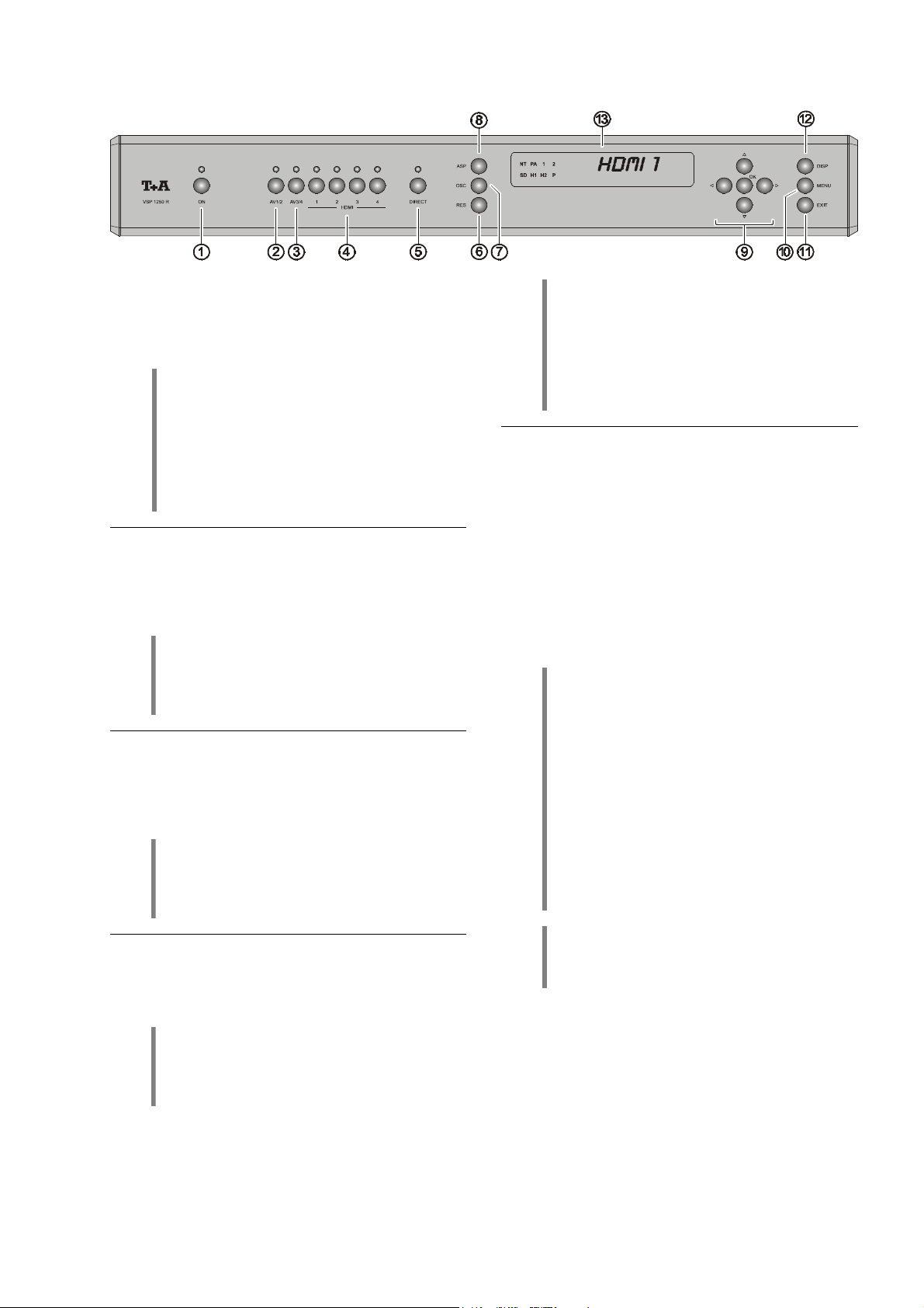
Bedienelemente der Frontseite
Ein- / Aus–Taster des Gerätes.
Nach dem Einschalten leuchtet das Display auf und zeigt
die angewählte Bildquelle.
AV1/2
Durch ggf. wiederholtes Antippen dieses Tasters wählen
Sie die analogen Bildeingänge AV1 (Composite) und
AV2 (S-Video).
AV3/4
Durch ggf. wiederholtes Antippen dieses Tasters wählen
Sie die analogen Bildeingänge AV3 (YUV) und AV4
(RGB/Scart).
ON
Achtung:
Der Ein-/Aus–Taster an der Gerätefront ist kein
Netztrenner. Es sind noch wenige Baugruppen
des Gerätes mit der Netzspannung verbunden.
Soll die Anlage längere Zeit nicht benutzt
werden, ist es empfehlenswert, das Gerät von
der Netzspannung zu trennen. Dazu muss der
Netzstecker gezogen werden.
Hinweis:
Im Verbund mit einem B Surroundreceiver
oder -decoder SR 1535 R / DD 1535 R geschieht
die Quellenwahl automatisch.
Hinweis:
Im Verbund mit einem B Surroundreceiver
oder -decoder SR 1535 R / DD 1535 R geschieht
die Quellenwahl automatisch.
Mit diesem Schalter können HDMI Eingangssignale
direkt zu den HDMI und DVI Monitorausgängen durchgeschaltet werden (DIRECT-Funktion). Der interne
Videoprozessor des VSP 1250 R wird dabei überbrückt.
Die Direktfunktion wird durch die LED über dem Taster
angezeigt.
Wenn als Ausgangsauflösung eines der Sonderformate
XGA oder CT50HD (WXGA) gewählt ist, muss zwingend
eine Formatumwandlung im Videoprozessor erfolgen. Ein
Einschalten der DIRECT-Funktion ist daher bei diesen
Ausgangsformaten nicht möglich.
Hinweis:
Beim Umschalten zwischen den Bildeingängen
dauert es einige Sekunden, bis das Bild der
neuen Quelle angezeigt wird. Die Umschaltzeit
ist eine Folge des sehr komplexen Verbindungsaufbaus, der durch das vorgeschriebene Kopierschutzverfahren HDCP bedingt ist.
Hinweis:
Wenn die Direktfunktion aktiv ist, werden vom
VSP 1250 R keinerlei Bildbearbeitungen wie
Skalierung, Farbanpassungen etc. vorgenommen.
Alle Bildeinstellungen müssen deshalb bei
aktiver Direktfunktion entweder am Quellgerät
oder am Videomonitor erfolgen.
Wir empfehlen, die Direktfunktion nur bei Bildquellen zu verwenden, deren Bildformat mit der
nativen Auflösung Ihres Videomonitors exakt
übereinstimmt – also z. B. bei einer Full HD
Quelle mit 1920x1080 Bildpunkten an einem
Full HD Anzeigepanel mit ebenfalls 1920x1080
Bildpunkten.
(nur bei HDMI-Eingängen)
HDMI
Mit diesen Tastern wählen Sie einen der digitalen HDMI
Eingänge 1 - 4.
Hinweis:
Im Verbund mit einem B Surroundreceiver
oder -decoder SR 1535 R / DD 1535 R geschieht
die Quellenwahl automatisch.
5
Hinweis:
Bei Direktbetrieb werden keine ON-Screen Einblendungen (MENU etc.) dargestellt.
Page 6

RES
Einstellung der Ausgangsauflösung.
Mit diesem Taster kann die Bildausgabe des VSP 1250 R
an die Auflösung und Geometrie Ihres Videomonitors angepasst werden.
Zur Einstellung der Auflösung ermitteln Sie bitte zuerst
anhand der Bedienungsanleitung die native Auflösung
Ihres Videomonitors (z. B. 720p = 1280x720 Bildpunkte).
Drücken Sie nun den RES Taster so lange, bis im
Display an der Gerätefront die aktuell eingestellte Auflösung erscheint. Durch ggf. mehrfaches kurzes Antippen
des RES Tasters können Sie nun die gewünschte Ausgangsauflösung auswählen.
Es stehen folgende Ausgangsauflösungen zur Verfügung:
a) die genormten (SMPTE) Auflösungen
Auflösung Bildpunkte Progr.
Doubling 480/576p 1440x576/480 p
HDTV 720p 1280x720 p
HDTV 1080i 1920x1080 i
HDTV 1080p 1920x1080 p
Die Anpassung der Auflösung muss nur einmal
passend für Ihren Videomonitor eingestellt
werden und braucht danach im Betrieb nicht
mehr verändert zu werden.
Diese Funktion ist nicht fernbedienbar, um ein
versehentliches Verstellen zu verhindern.
interl.
OSC (Overscan)
Mit diesem Taster wird die Overscan Funktion ein- und
ausgeschaltet. Die Overscaneinstellung wird für jede
Quelle individuell gespeichert.
Unter Aspect Ratio versteht man das Seitenverhältnis der
Bildwiedergabe. Die gebräuchlichsten Seitenverhältnisse
sind das vom Fernsehen der früheren Jahre bekannte
4:3 und das mit der DVD im Heimbereich eingeführte
16:9 Breitbildformat.
Der VSP 1250 R kann die verschiedensten Bildformate
der Quellgeräte an die Geometrie Ihres Videomonitors
optimal anpassen.
Durch wiederholtes Antippen des ASP Tasters können
Sie die verschiedenen Anpassungsfaktoren des
VSP 1250 R durchschalten. Wählen Sie auf diese Weise
den entsprechenden Anpassungsfaktor, um das von der
Quelle gelieferte Bild möglichst Format füllend und unverzerrt auf Ihrem Monitor darzustellen.
Details und nähere Erläuterungen zu dieser Einstellung
finden Sie im Kapitel 'Glossar / Wissenswertes' unter
dem Punkt 'Seitenverhältnis – Aspect Ratio – Die
Wahl des richtigen Anpassungsfaktors'.
Hinweis:
Wir empfehlen, die Overscanfunktion nur bei
Bildquellen zu verwenden, deren Bilder an den
äußeren Rändern unsauber auf Ihrem Monitor
erscheinen.
ASP (Aspect Ratio)
b) die zusätzlichen teilweise bei Displays anzutreffenden
Auflösungen
Auflösung Bildpunkte Progr.
interl.
WXGA60c /
CT 50 HD (Cinemateq®) 1366x768 p
XGA 1024x768 p
Sobald die gewünschte Auflösung im Display erscheint,
drücken Sie den RES Taster so lange, bis diese Auflösung aktiviert wird – erkenntlich durch die entsprechende LED im Display.
Achtung:
Manche Monitore können nicht sämtliche
Auflösungen wiedergeben, die der VSP 1250 R
beherrscht.
Bei falscher Einstellung der Ausgangsauflösung kann es passieren, dass Ihr Monitor kein oder nur ein stark gestörtes Bild
ausgibt. Schalten Sie in einem solchen Fall
den VSP 1250 R bitte umgehend wieder auf
eine Auflösung zurück, die Ihr Monitor beherrscht.
6
Page 7
/ / /
Taster zur Navigation innerhalb des Einstellmenüs.
Details zur Menüfunktion siehe Kapitel 'Menüsteuerung'.
Im Einstellmenü
Aktiviert einen Menüpunkt zur Einstellung. Nach erfolgter
Einstellung beendet dieser Taster die Einstellfunktion und
übernimmt den eingestellten Wert.
Außerhalb des Einstellmenüs
Ein Antippen dieses Tasters bringt eine INFOBOX auf
Ihren Videomonitor, in der die aktuellen Einstellungen
des VSP 1250 R übersichtlich angezeigt werden.
Öffnet das Einstellmenü des VSP 1250 R.
Das Einstellmenü des VSP 1250 R wird auf Ihrem Monitor dargestellt und mit den Navigationstastern (s. o.)
bedient.
Nähere Erläuterungen zu den einzelnen Einstellfunktionen des Menüs finden Sie im Kap. 'Menüsteuerung'.
Mit diesem Taster schließen Sie das Einstellmenü und
beenden Einblendungen auf Ihrem Videomonitor.
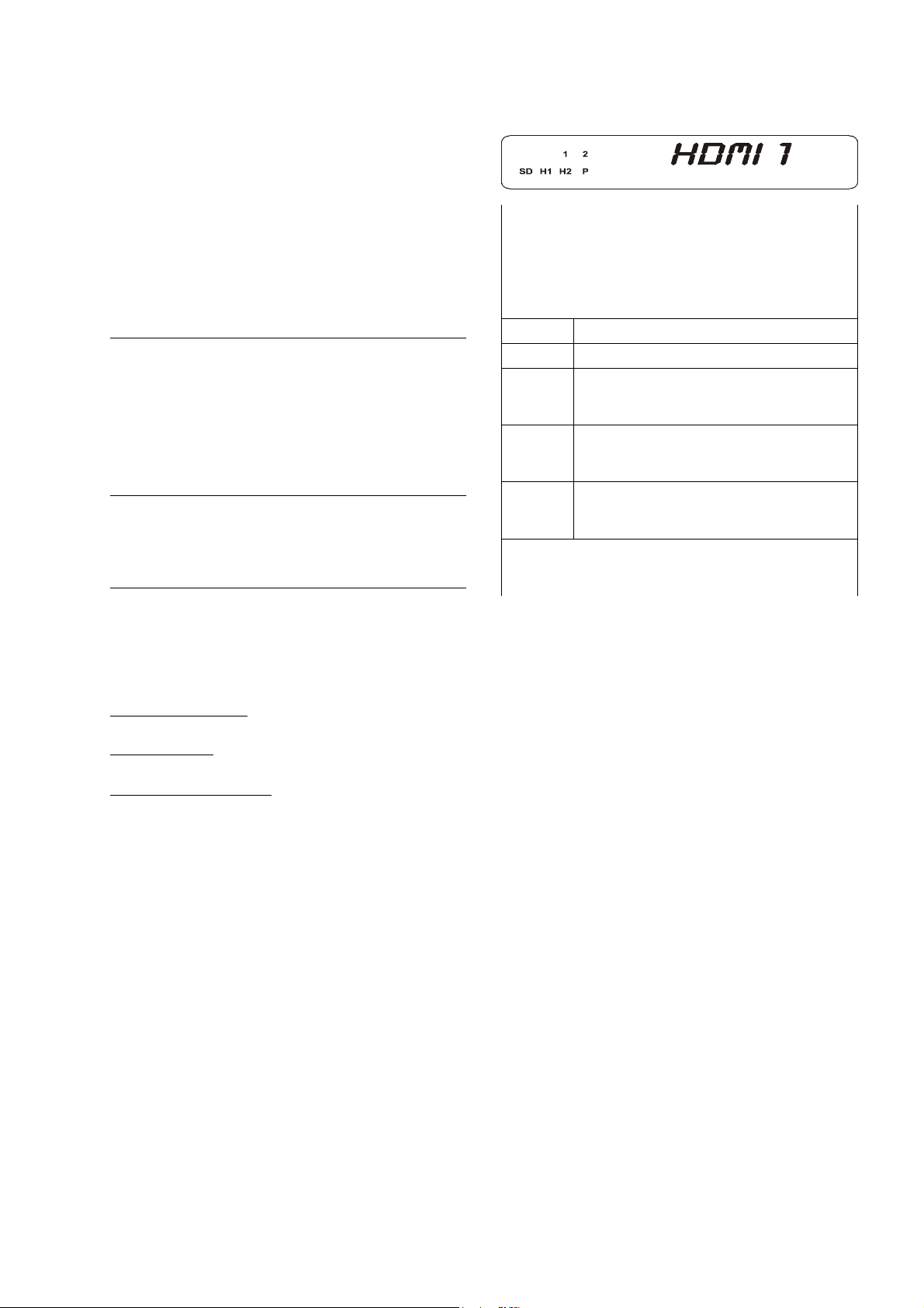
Display
Alle Anzeigeelemente des VSP 1250 R sind in einem
übersichtlichen Displayfenster zusammengefasst:
HDMI
HDMI 1111
HDMIHDMI
SD Dieser Indikator leuchtet, wenn ein Signal
H1 Dieser Indikator leuchtet, wenn ein hochauf-
H2 Dieser Indikator leuchtet, wenn ein hochauf-
Alphanumerisches Displayfeld
Hier wird im Normalfall die gerade gewählte
Bildquelle und die Signalart angezeigt.
Das alphanumerische Displayfeld dient
gelegentlich auch zur Anzeige von Statusmeldungen oder anderer Bedienhinweise.
1 XGA
2 CT 50 HD
mit Standardauflösung (480 oder 576
Zeilen) ausgegeben wird.
gelöstes Bildsignal mit 720 oder 768 Zeilen
ausgegeben wird.
gelöstes Bildsignal mit 1080 Zeilen ausgegeben wird.
P Dieser Indikator leuchtet, wenn Bilder im
Vollbildmodus (Progressive Scan) ausgegeben werden.
Durch wiederholtes Drücken des
die Helligkeit der alphanumerischen Displayzeilen in drei
Stufen den persönlichen Wünschen angepasst werden.
Folgende Helligkeitsstufen stehen zur Wahl:
1. Normaleinstellung:
gute Ablesbarkeit, auch bei Tage und Sonnenlicht
2. Abgedunkelt:
dezente Einstellung, für dunkle Aufstellungsorte
3. Display ausgeschaltet:
das Display ist vollständig abgeschaltet
In der Helligkeitsstufe 3 wird das Display bei jedem
Bedienvorgang für kurze Zeit aktiviert und auf normale
Helligkeit geschaltet. Dadurch wird eine Kontrolle der
Einstellungen auch aus größerer Entfernung gestattet.
Das Display schaltet nach ca. 4 Sekunden automatisch
wieder auf den gewählten Helligkeitswert zurück. Aus
diesem Grund wird auch ein neu gewählter Helligkeitswert erst nach ca. 4 Sekunden wirksam.
-Tasters kann
DISP
DISP NORM
NORM
DISPDISP
NORMNORM
DISP SOFT
DISP SOFT
DISP SOFTDISP SOFT
DISP OFF
DISP OFF
DISP OFFDISP OFF
7
Page 8
Fernbedienung des VSP 1250 R im
/
/
Kurz antippen schaltet das System auf Videoprozessorbedienung um.
Nach dem Antippen des Tasters erscheint im Display des SR 1535 R
und auf Ihrem Videomonitor die Meldung '
Fernbedienung werden nun zum VSP 1250 R durchgeleitet und Sie
können die gewünschten Einstellungen am VSP 1250 R vornehmen.
Hinweis:
Zum Zurückschalten auf Normalbedienung tippen Sie bitte auf den
Taster. Die Meldung '
wieder wie gewohnt Receiver und Quelle bedienen.
Nach dem Umschalten auf Videoprozessorbedienung kann durch ggf.
mehrfaches Antippen des
(Aspect Ratio) eingestellt werden.
Im Einstellmenü
Aktiviert einen Menüpunkt zur Einstellung. Nach erfolgter Einstellung
beendet dieser Taster die Einstellfunktion und übernimmt den eingestellten Wert.
Außerhalb des Einstellmenüs
Ein Antippen dieses Tasters bringt eine INFOBOX auf Ihren Videomonitor, in der die aktuellen Einstellungen des VSP 1250 R übersichtlich angezeigt werden. Erneutes Antippen des
schließt die INFOBOX wieder.
Auswahl eines Menüeintrages.
Veränderung eines Einstellwertes im Menü.
Hinweis:
Vor einer Wertveränderung muss der Menüpunkt durch Drücken des
Tasters aktiviert werden.
Beendet die Videoprozessorbedienung. Die Meldung '
schwindet und Sie können wieder wie gewohnt Quelle und Receiver
bedienen.
System
VIDEOPROC
VIDEOPROC
VIDEOPROCVIDEOPROC
Tasters das Bildseitenverhältnis
VIDEOPROC
VIDEOPROC
VIDEOPROCVIDEOPROC
' verschwindet und Sie können
'. Alle Taster der
Tasters
VIDEOPROC
VIDEOPROC
VIDEOPROCVIDEOPROC
' ver-
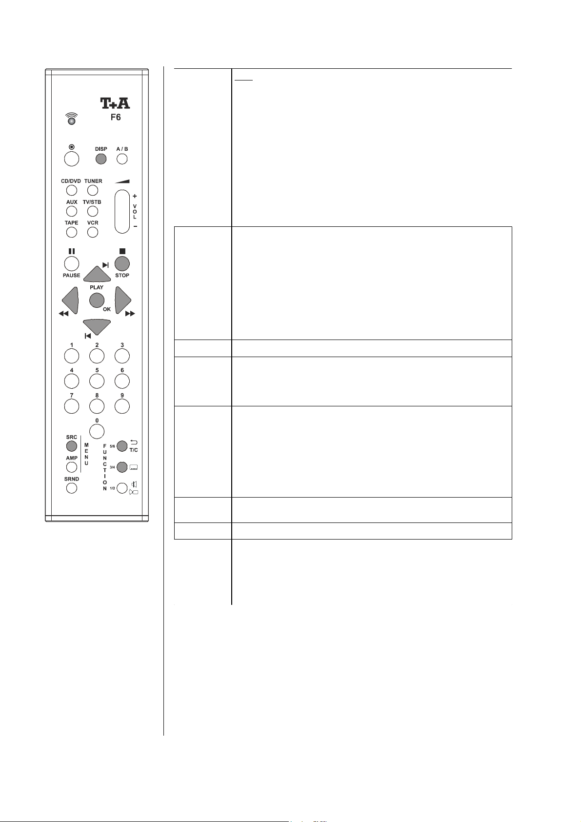
In einem B Heimkinosystem steuert die B
Systemfernbedienung F6
sämtliche Funktionen des
VSP 1250 R. Die vorgenommenen Einstellungen
werden auf dem Gerätedisplay und ggf. auf einem
angeschlossenen TV-Gerät
dargestellt.
Im Einstellmenü
Bricht eine Einstellung ohne zu speichern ab und wechselt zur nächsthöheren Menüebene. In der höchsten Ebene (MAIN MENU) wird das
Menü beendet.
Ein Druck auf diesen Taster öffnet das Einstellmenü des VSP 1250 R
(siehe Kapitel 'Menüsteuerung').
Antippen dieses Tasters schaltet die Overscan Funktion ein und aus.
Dieser Taster hat die gleiche Funktion wie der
Front.
Hinweis:
Bei Direktbetrieb werden keine ON-Screen Einblendungen (MENU
etc.) dargestellt.
Taster an der
8
Page 9
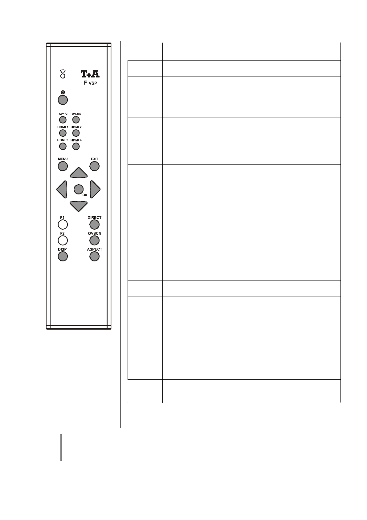
Fernbedienung des VSP 1250 R über die Fernbedienung F VSP
AV1/2
AV3/4
HDMI1
...
HDMI4
/
/
ON
Taster zum ein- und ausschalten des Gerätes.
Antippen dieses Tasters schaltet zwischen den analogen Bildeingängen AV1 und AV2 hin und her.
Antippen dieses Tasters schaltet zwischen den analogen Bildeingängen AV3 und AV4 hin und her.
Taster zur Umschaltung der HDMI Eingänge HDMI1 ... HDMI4.
Auswahl eines Menüeintrages.
Veränderung eines Einstellwertes im Menü.
Hinweis:
Vor einer Wertveränderung muss der Menüpunkt durch Drücken des
Tasters aktiviert werden.
Im Einstellmenü
Aktiviert einen Menüpunkt zur Einstellung. Nach erfolgter Einstellung
beendet dieser Taster die Einstellfunktion und übernimmt den eingestellten Wert.
Außerhalb des Einstellmenüs
Ein Antippen dieses Tasters bringt eine INFOBOX auf Ihren Videomonitor, in der die aktuellen Einstellungen des VSP 1250 R übersichtlich angezeigt werden.
im Einstellmenü
Bricht eine Einstellung ohne zu speichern ab und wechselt zur nächsthöheren Menüebene. In der höchsten Ebene (MAIN MENU) wird das
Menü beendet.
Die Fernbedienung F VSP
steuert sämtliche Funktionen
des VSP 1250 R. Die vorgenommenen Einstellungen
werden auf dem Gerätedisplay und ggf. auf einem
angeschlossenen TV-Gerät
dargestellt.
Hinweis:
Um den VSP 1250 R direkt mit der Fernbedienung F VSP bedienen zu können, muss der Infrarotempfänger
E2000 an der rückseitigen Anschlussbuchse angeschlossen sein.
Außerhalb des Einstellmenüs
Beendet Bildschirmeinblendungen.
Antippen dieses Tasters öffnet und schließt das Einstellmenü des
VSP 1250 R.
Dieser Taster hat die gleiche Funktion wie der
Front.
Hinweis:
Bei Direktbetrieb werden keine ON-Screen Einblendungen (MENU
etc.) dargestellt.
Dieser Taster hat die gleiche Funktion wie der ASP Taster an der
Front.
Ein Antippen dieses Tasters schaltet das Seitenverhältnis für die Bildausgabe um.
Antippen dieses Tasters schaltet die Overscan Funktion ein und aus.
Dieser Taster hat die gleiche Funktion wie der
Front.
Ein Antippen dieses Tasters schaltet die Displayhelligkeit um.
Taster an der
Taster an der
9
Page 10

Der VSP 1250 R im praktischen Betrieb
mit einem B
B Surroundreceiver SR 1535 R oder -decoder DD 1535 R
BB
Betrieb im Systemverbund
Wenn Sie Ihren VSP 1250 R im Verbund mit einem
SR 1535 R (*) oder DD 1535 R (*) betreiben, werden fast
alle Bedienvorgänge vollständig automatisiert.
Schalten Sie einfach Ihren Videomonitor ein und wählen
Sie am Monitor den HDMI Eingang (oder bei DVI Verkabelung den DVI Eingang).
Wählen Sie nun am B System die gewünschte Quelle
z. B. DVD. Nach kurzer Umschaltzeit erscheint nun das
Bild des DVD Spielers auf dem Monitor und Sie hören
den dazugehörigen Ton. Gleichzeitig mit der Quellenwahl
stellt das System Ihre bevorzugten Bild- und Toneinstellungen für dieses Gerät her (siehe 'Quellenbezogene
Presets' im Kapitel 'Wissenswertes / Glossar').
Sie müssen nun nur noch auf den
Fernbedienung tippen und schon beginnt die Vorstellung.
Hinweis:
Manche Videomonitormodelle bieten eine Automatikeinschaltung, die das Gerät einschaltet,
sobald ein HDMI Signal am Eingang anliegt.
Taster Ihrer F6
(*) Hinweis:
Für die Systemkombination mit dem VSP 1250 R
müssen die B Surroundreceiver / Decoder
einen Mindestsoftwarestand aufweisen. Nähere
Hinweise hierzu s. Kapitel 'Technische Daten'.
Anpassung des Seitenverhältnis
Die einzige Funktion, die Sie bei einem B Komplettsystem mit SR 1535 R oder DD 1535 R gelegentlich
benötigen werden, ist die Einstellung des richtigen
Seitenverhältnisses (4:3 / 16:9).
Immer wenn das Bild der Quelle nicht korrekt auf Ihrem
Monitor abgebildet wird, wählen Sie bitte mit dem Taster
ASP an der Gerätefront des VSP 1250 R den zum
laufenden Programm passenden Konvertierungsfaktor.
(siehe auch Kapitel 'Wissenswertes / Glossar').
Die Anpassung des Seitenverhältnisses können Sie auch
bequem aus Ihrem Sessel per Fernbedienung vornehmen. Gehen Sie dazu bitte wie folgt vor:
• Durch einen kurzen Druck auf den
F6 schalten Sie das System auf VSP 1250 R Bedienung. Es erscheint nun die Meldung '
Display des SR 1535 R und auf Ihrem Videomonitor,
um anzuzeigen, dass Sie nun den VSP 1250 R mit
Ihrer Fernbedienung bedienen können.
• Nun können Sie das Seitenverhältnis durch ggf. mehrfaches Drücken des
• Nach erfolgter Einstellung beenden Sie die
VSP 1250 R Bedienung durch einen erneuten kurzen
Druck auf den
Andere Einstellungen
Sollten Sie irgendwann einmal andere Einstellungen wie
Kontrast, Helligkeit usw. vornehmen wollen, so können
Sie dies direkt über die Tasten an der Gerätefront tun.
Alternativ können Sie natürlich auch Ihre Fernbedienung
benutzen. Dazu gehen Sie genau wie oben vor:
• Umschalten auf VSP 1250 R Bedienung mit dem
Taster.
• Durchführen der Einstellung mit den direkten Tastern
der F6 (s. Kap. 'Fernbedienung des VSP 1250 R')
oder über das Einstellmenü (s. Kap. 'Menüsteuerung').
• Beenden der VSP 1250 R Bedienung mit dem
Taster.
Taster anpassen.
Taster.
Taster der
VIDEOPROC
VIDEOPROC
VIDEOPROCVIDEOPROC
' im
10
Hinweis:
Alle Bild- und Toneinstellungen, die Sie am
B System vornehmen, merkt sich das
System individuell für jedes Quellgerät.
Für Details zu diesem Thema siehe 'Quellen-
bezogene Presets' im Kapitel 'Glossar /
Wissenswertes'.
Page 11

Direkte Bedienung des VSP 1250 R in Kombination mit anderen Surround Receivern
Schalten Sie den VSP 1250 R, Ihren Videomonitor, den
Surroundreceiver und das Quellgerät ein.
Wählen Sie am Videomonitor den HDMI Eingang (oder
bei DVI Verkabelung den DVI Eingang).
HDMI Quellen
Wählen Sie bei HDMI Quellen am VSP 1250 R oder mit
der Fernbedienung F VSP den HDMI Eingang
(HDMI1 ... HDMI4), an den die Quelle angeschlossen ist.
Sie sollten nun nach kurzer Zeit das Bild der Quelle auf
Ihrem Monitor sehen.
Wählen Sie an Ihrem Surroundreceiver nun den
(digitalen) Toneingang, an den das Quellgerät entweder
direkt angeschlossen ist bzw. an den der digitale Tonausgang des VSP 1250 R angeschlossen ist. Nun sollten Sie
auch den Ton der Quelle hören.
Receiver Bedienmenüs bei HDMI Quellen
Einstellungen an Surroundreceivern werden häufig über
Bildschirmmenüs vorgenommen. Um solch ein Menü auf
Ihrem Monitor darzustellen, muss der VSP 1250 R für die
Dauer der Menübedienung auf den analogen Videoeingang (AV1 ... AV4) umgeschaltet werden, an den der
Videoausgang Ihres Receivers angeschlossen ist. Nach
Beendigung des Bedienmenüs, schalten Sie wieder auf
den Videoeingang des VSP 1250 R zurück, an dem Ihre
Quelle angeschlossen ist.
Einstellungen am VSP 1250 R
Sollten während des Betriebes Bildeinstellungen am
VSP 1250 R notwendig sein, so können Sie diese jederzeit entweder über die Taster an der Gerätefront vornehmen (s. Kap. 'Bedienelemente der Frontseite') oder
über die Fernbedienung F VSP (s. Kap. 'Fernbedienung
des VSP 1250 R über die Fernbedienung F VSP').
Hinweis:
Alle Bildeinstellungen, die Sie am VSP 1250 R
vornehmen, merkt sich das Gerät individuell für
jeden der acht Eingänge HDMI1 ... HDMI4 und
AV1 ... AV4.
Für Details zu diesem Thema siehe 'Quellen-
bezogene Presets' im Kapitel
'Glossar/Wissenswertes'.
Analoge Videoquellen
Bei analogen Bildquellen wählen Sie zunächst am
Receiver das gewünschte Quellgerät aus. Schalten Sie
den VSP 1250 R nun auf denjenigen analogen Bildeingang (AV1 ... AV4), an dem der Videoausgang des
Receivers angeschlossen ist. Sie sollten nun nach kurzer
Zeit das Bild der Quelle auf dem Monitor angezeigt
bekommen.
Hinweis:
Falls Ihr Receiver mehrere Videoausgänge hat,
die an den VSP 1250 R angeschlossen sind, so
wählen Sie am VSP 1250 R bitte den analogen
Bildeingang, der zu der Signalart des gerade
gewählten Quellgerätes passt. Also den AV1
Eingang bei Standard-Videoquellen, AV2 bei SVideo und AV3 bei YUV Videoquellen.
Wählen Sie den SCART-Eingang des
VSP 1250 R bei Receivern mit SCART
Ausgang.
11
Page 12
Menü Steuerung
Der VSP 1250 R verfügt über ein komfortables Bildschirmmenü zur Einstellung aller Bildparameter. Mit Hilfe dieses
Menüs können Sie die Bildwiedergabe optimieren und Ihren persönlichen Vorlieben anpassen.
Die Bildeinstellungen, die Sie im Menü vornehmen, gelten immer nur für die jeweils aktive Bildquelle. Sie werden vom
VSP 1250 R für jede Bildquelle separat abgespeichert. Beim Quellenwechsel ruft der VSP 1250 R die Bildwerte für die
neue Quelle aus seinem Speicher ab und stellt sämtliche Bildparameter automatisch wieder so ein, wie Sie sie für diese
Quelle eingestellt haben. Auf diese Weise können Sie Bildunterschiede wie z. B. abweichende Kontrast- oder Farbwiedergabe zwischen einzelnen Quellgeräten gezielt ausgleichen.
Bedienung des Einstellmenüs im B
B System
BB
über die Systemfernbedienung F6
Zuerst muss der B Surroundreceiver / Surrounddecoder auf VSP 1250 R Bedienung geschaltet werden.
Tippen Sie dazu den
VSP 1250 R Bedienmode wird auf dem Display des
Surroundreceivers und dem Videomonitor durch die
Meldung '
Nach der Umschaltung der Bedienung tippen Sie nun auf
den
Im Menü können Sie mit den / Tastern einen
Menüeintrag auswählen.
Um eine Einstellung zu verändern, aktivieren Sie zuerst
den gewünschten Menüeintrag mit dem
Es erscheint dann eine Einstellbox, bei der der aktuell
eingestellte Wert orange hervorgehoben ist. Verändern
Sie nun die Einstellung mit Hilfe der / Taster.
Nachdem Sie die gewünschte Einstellung gefunden
haben, bestätigen Sie diese durch einen Druck auf den
Taster. Die Einstellung wird nun für die gerade
aktive Bildquelle gespeichert.
Um einen Menüpunkt oder ein Untermenü zu verlassen,
drücken Sie den
Zum Schließen des Menüs tippen Sie den
ggf. mehrfach an, bis sich das Menü schließt.
VIDEOPROC
VIDEOPROC
VIDEOPROCVIDEOPROC
Taster, um das Einstellmenü zu öffnen.
Taster der F6 kurz an. Der
' angezeigt.
Taster.
Taster der F6.
Taster
Bedienung des Einstellmenüs über die Taster an
der Gerätefront oder die Fernbedienung F VSP
Das Einstellmenü kann auch direkt am Gerät über die
Taster an der Gerätefront oder über die optionale Fernbedienung F VSP bedient werden.
Zum Öffnen des Menüs dient der
Die Bedienung erfolgt mit den Cursortastern , ,
, und mit dem
schrieben.
Das Schließen und Verlassen des Menüs erfolgt durch
einen Druck auf den
Taster.
Taster.
Taster wie links be-
Menü-Übersicht
12
Page 13
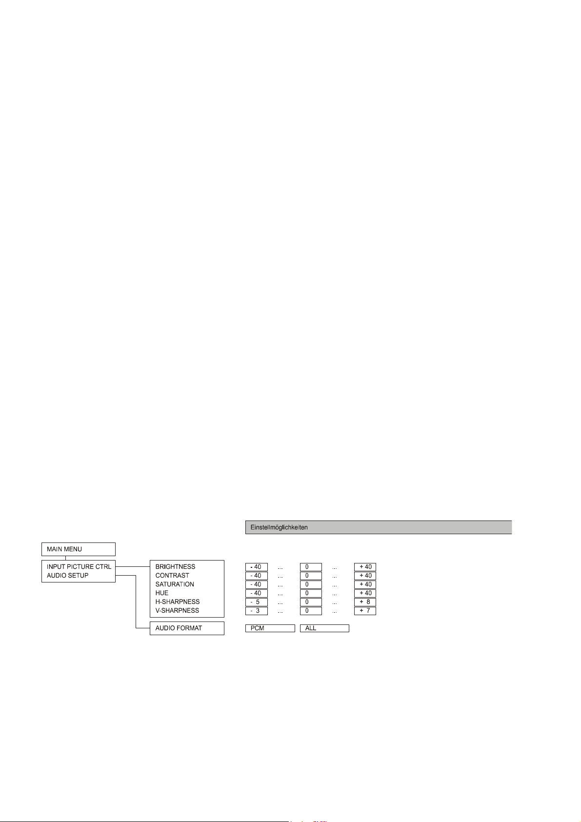
Einstellungen im Menü des VSP 1250 R
MAIN MENU
Nach dem Öffnen des Menüs wird zunächst das Hauptmenü (MAIN MENU) angezeigt. Im Hauptmenü können
die Untermenüs zur Bild- bzw. Toneinstellung aufgerufen
werden.
Untermenü:
In diesem Untermenü können die Bildparameter für den gerade aktiven Eingang eingestellt werden.
INPUT PICTURE CTRL.
Hinweis:
Die Quelle, für die Sie gerade die Einstellungen
vornehmen, wird Ihnen im Display des
VSP 1250 R angezeigt:
• bei B Systemen im 'Klartext' z. B. 'DVD'
oder 'VCR1'.
• bei Betrieb des VSP 1250 R außerhalb von
B Surroundsystemen z. B. 'HDMI1' oder
'AV1'.
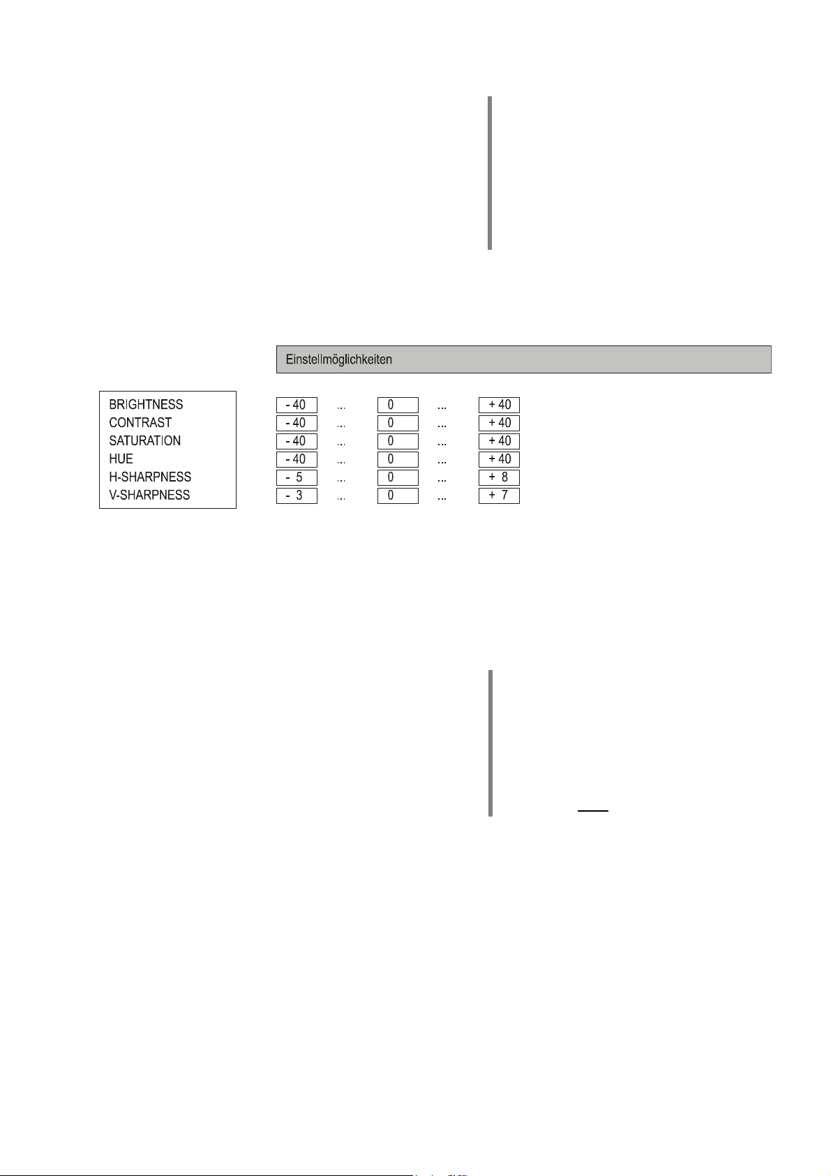
Im 'INPUT PICTURE CTRL' Menü stehen folgende Einstellmöglichkeiten zur Verfügung:
• BRIGHTNESS = Helligkeit [-40 ... +40]
Stellen Sie die Helligkeit bitte so ein, dass schwarze
Stellen des Bildes schwarz abgebildet werden. Am
besten geschieht diese Einstellung mit einem geeigneten Testbild (z. B. Universaltestbild).
• CONTRAST = Kontrast [-40 ... +40]
Stellen Sie den Kontrast bitte so ein, dass weiße
Stellen des Bildes rein weiß abgebildet werden. Am
besten geschieht diese Einstellung mit einem geeigneten Testbild (z. B. Universaltestbild).
• SATURATION = Farbsättigung [-40 ... +40]
Mit dieser Einstellung beeinflussen Sie die Farbstärke.
Wählen Sie eine Einstellung, bei der sich eine natürliche Farbwiedergabe ergibt. Zur Einstellung sind reale
Standbilder oder Filmsequenzen am Besten geeignet.
• HUE = Farbton [-20 ... +20]
Mit dieser Einstellung können Sie die Farbbalance
(Tönung) verändern. Nehmen Sie auch diese Einstellung am Besten mit Realbildern, z. B. Hauttönen,
vor.
• H-SHARPNESS = horiz. Schärfe [- 5 ...+ 8]
• V-SHARPNESS = vertik. Schärfe [- 3 ...+ 7]
Diese Einstellpunkte beeinflussen die Schärfe der Abbildung. Insbesondere bei schlechten Bildquellen kann
die subjektive Bildwahrnehmung verbessert werden,
wenn Sie die Schärfe der Qualität des Bildmaterials
anpassen.
Hinweis:
Bei analogen Videoquellen kann die Schärfe
nicht getrennt für horizontal und vertikal eingestellt werden. Der Menüpunkt 'V-SHARPNESS'
ist bei analogen Quellen nicht anwählbar.
Hinweis:
Die Einstellung der Schärfe wirkt sich auf den
YUV-Eingang nicht aus.
13
Page 14

Untermenü
Das Audio Setup Menü dient zur Einstellung der über die HDMI Anschlüsse des VSP 1250 R entgegengenommenen und
ausgegebenen Audiosignale.
AUDIO FORMAT
In diesem Untermenü wird eingestellt, welche Audiosignale von den an die HDMI Eingänge des VSP 1250 R
angeschlossenen Zuspielgeräten angefordert werden:
• PCM (nicht für Surroundbetrieb!)
Es werden von der Quelle reine Stereo PCM Audiodaten angefordert. Diese Einstellung sollte ausschließlich dann gewählt werden, wenn es sich bei dem mit
dem VSP 1250 R verbundenen Audiosystem
(Receiver/Verstärker) um ein reines STEREO System
handelt.
Achtung:
Diese Einstellung ist nicht geeignet, wenn der
von der Quelle per HDMI zugespielte Ton vom
VSP 1250 R zu einem Surround-Receiver
weitergeleitet werden soll.
AUDIO SETUP
• ALL (empfohlene Einstellung bei Betrieb mit einem
Surround-Receiver)
In dieser Einstellung wird den an den VSP 1250 R
angeschlossenen HDMI Quellgeräten signalisiert, dass
alle Stereo und Surround Audiosignalarten akzeptiert
werden. Diese Einstellung muss gewählt werden, wenn
der von der Quelle per HDMI gelieferte Ton vom
VSP 1250 R an einen Surround Receiver weitergeleitet
werden soll.
14
Page 15

Installation
Inbetriebnahme
Sicherheitshinweise
In diesem Kapitel werden alle Dinge von grundsätzlicher Bedeutung für die Aufstellung und Inbetriebnahme
beschrieben, die nicht für den täglichen Umgang mit dem Gerät relevant sind, die aber trotzdem vor dem ersten
Gebrauch gelesen und beachtet werden sollten.
15
Page 16
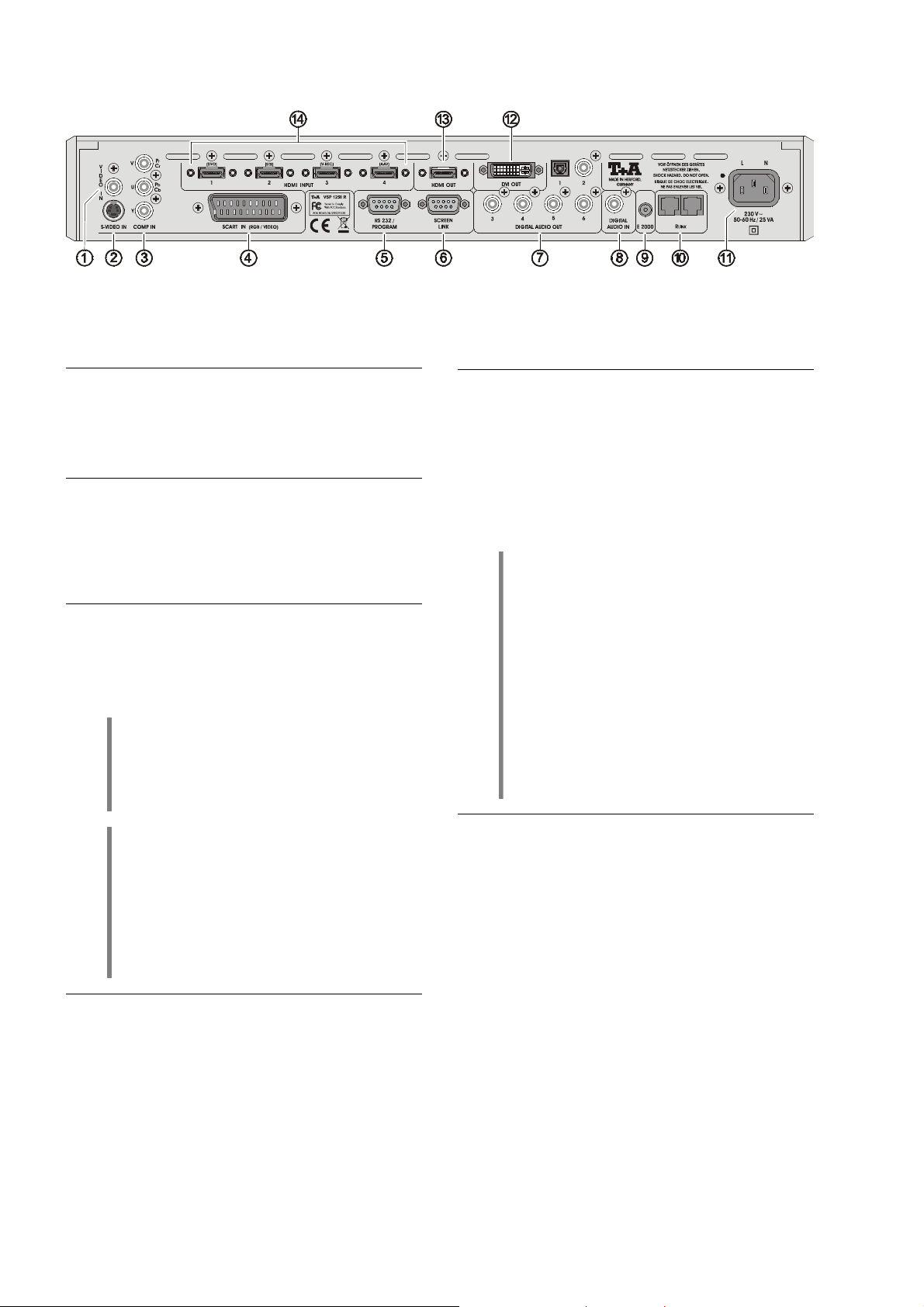
Anschlusselemente
VIDEO IN
Bei Anwahl des Videoeingangs AV1 werden die hier
anliegenden Videosignale digitalisiert und zum VideoMonitor per HDMI oder DVI übertragen.
S-VIDEO IN
Bei Anwahl des Videoeingangs AV2 werden die hier
anliegenden S-Videosignale digitalisiert und zum VideoMonitor per HDMI oder DVI übertragen.
COMP IN
Bei Anwahl des Videoeingangs AV3 werden die hier
anliegenden YUV Videosignale (Component-Video)
digitalisiert und zum Video-Monitor per HDMI oder DVI
übertragen.
SCART IN
Bei Anwahl des Videoeingangs AV4 werden die hier
anliegenden Videosignale digitalisiert und zum VideoMonitor per HDMI oder DVI übertragen.
Hinweis
Stehen auf der SCART Buchse sowohl RGB als
auch FBAS Videosignale an, so wählt der
VSP 1250 R automatisch die hochwertigeren
RGB Komponentensignale.
Eingang für Standard-Videosignale
Eingang für S-Videosignale
Eingang für YUV Video Signale
Eingang für RGB und
Composite (FBAS) Videosignale.
SCREEN LINK
Steuerschnittstelle für dafür vorbereitete Metz TV-Geräte
und Flachbildschirme. Diese TV Geräte können auch
über die BBBB F6 Fernbedienung bedient werden.
DIGITAL AUDIO OUT
Digitale Audio Ausgänge.
Der VSP 1250 R kann Tonsignale, die von HDMI Quell-
geräten per HDMI Schnittstelle geliefert werden, auskoppeln. Die ausgekoppelten Tonsignale stehen an den
6 (coaxialen und optischen) DIGITAL AUDIO OUT
Buchsen an und können von hier zur weiteren Decodierung an einen Surround Receiver weitergeleitet
werden.
Hinweis:
Alle coaxialen und optischen DIGITAL AUDIO
OUT Ausgänge des VSP 1250 R sind gleichwertig und führen stets das gleiche Signal (das
Tonsignal der gerade gewählten HDMI Quelle).
Hinweis:
Für jede Quelle, die den Ton über HDMI liefert,
muss ein separates digitales Audiokabel zum
Receiver gelegt werden. Dem HDMI Gerät ist
der entsprechende digitale Toneingang des
Receivers zuzuweisen.
( siehe auch Angaben in den Verdrahtungsbildern im Kapitel 'Anschlussbeispiele').
Steueranschluss zur Fernsteuerung des VSP 1250 R und
zur Integration in vernetzte Multimedia-Anlagen.
Zusatzfunktion:
Programmierschnittstelle für Software-Upgrades.
Hinweis zu
In einem B Surroundsystem mit SR 1535 R
bzw. DD 1535 R wählt der VSP 1250 R bei
Anwahl einer analogen Bildquelle automatisch
den korrekten analogen Bildeingang AV1-AV4.
Dazu muss im SETUP Menü des Receivers /
Decoders jeder Bildquelle die dem Gerät entsprechende Signalart eingestellt sein.
RS 232 / PROGRAM
bis
DIGITAL AUDIO IN
Digitaler Audio Eingang.
Ein hier anliegendes digitales Audiosignal wird über die
HDMI OUT Buchse zu einem dort angeschlossenen Video
Monitor übertragen (z. B. für einen Monitor im
Nebenraum). Wenn der am HDMI Ausgang angeschlossene Monitor keinen Ton wiedergeben soll, kann dieser Eingang frei bleiben.
16
Page 17

E2000
Eingangsbuchse für den -Fernbedienungsempfänger
E2000 (im optionalen Fernbedienungsset FBS-VSP ent-
halten). Über den Empfänger kann der VSP 1250 R mit
der Fernbedienung F VSP außerhalb von B Systemen
direkt fernbedient werden.
Steuerschnittstelle zum Anschluss des VSP 1250 R an
-Geräte (z. B. Surroundreceiver SR 1535 R oder
Surrounddecoder DD 1535 R) mit R
Über diese Schnittstelle wird der VSP 1250 R in B
Heimkinosysteme eingebunden und kann mit der F6
Systemfernbedienung fernbedient werden.
Hinweis
Der E2000 darf nicht angeschlossen werden,
wenn der VSP 1250 R über R
Systemanlage angeschlossen ist.
R
LINK
Hinweis
Surroundreceiver (SR 1535 R) bzw. Decoder
(DD 1535 R) müssen zum Betrieb mit dem
VSP 1250 R Mindestanforderungen bezüglich
ihres Softwarestandes erfüllen. Nähere Angaben
hierzu finden Sie im Kap. 'Technische Daten'
am Ende dieser Betriebsanleitung.
LINK
LINK
-Steuerung.
an eine B
Aufstellung des Gerätes
Packen Sie das Gerät vorsichtig aus und heben Sie die
Originalverpackung sorgfältig auf. Der Karton und das
Verpackungsmaterial wurden speziell für dieses Gerät
konzipiert. Sie haben damit - auch für spätere Transporte
- eine sichere Verpackung.
Lesen Sie die Sicherheitshinweise dieser Anleitung und
beachten Sie bei der Aufstellung alle dort gemachten
Angaben!
War das Gerät größerer Kälte ausgesetzt (z. B. beim
Transport), so ist mit der Inbetriebnahme zu warten, bis
sich das Gerät auf Raumtemperatur aufgewärmt hat und
das Kondenswasser restlos verdunstet ist.
Vor der Aufstellung des Gerätes auf empfindlichen
Flächen sollte ggf. an einer nicht sichtbaren Stelle die
Verträglichkeit des Lackes mit den Gerätefüßen überprüft
werden.
Das Gerät ist waagerecht auf einer festen, ebenen Unterlage aufzustellen. Es ist darauf zu achten, dass die
Standsicherheit des Gerätes nicht beeinträchtigt wird.
Die Aufstellung darf nur an einem gut belüfteten,
trockenen Ort erfolgen, wobei direkte Sonneneinstrahlung und die Nähe von Heizkörpern zu vermeiden
sind. Das Gerät darf nicht in der Nähe von wärmeproduzierenden, wärmeempfindlichen oder leicht brennbaren
Gegenständen bzw. Geräten aufgestellt werden.
Beim Aufstellen ist darauf zu achten, dass die Kühlluftzufuhr nicht behindert wird; die Kühlschlitze müssen frei
bleiben!
Netzanschluss
In diese Buchse wird das Netzkabel eingesteckt.
DVI OUT
Digitaler DVI Videoausgang zum Anschluss von DVI
Videomonitoren.
Der DVI Monitor muss das HDCP Kopierschutz-
Digitaler HDMI Videoausgang zum Anschluss von HDMI
Videomonitoren.
HDMI Eingänge zum Anschluss von HDMI Quellgeräten.
Es können Geräte mit allen SMPTE Auflösungen bis
1080p angeschlossen werden.
verfahren unterstützen. Ansonsten wird vom
VSP 1250 R kein Bild an den Monitor ausgegeben.
HDMI OUT
HDMI Eingänge
Hinweis:
Die HDMI Buchsen des VSP 1250 R sind für
verschraubbare B HDMI Kabel vorbereitet.
Durch die Verschraubung haben die Kabel
einen festen Sitz. Sie können sich nicht lockern
und eine langfristig optimale und störungsfreie
Übertragungsqualität ist gewährleistet.
Ein Wärmestau beeinträchtigt die
Lebensdauer des Gerätes und ist eine
Gefahrenquelle!
Falls bei der Inbetriebnahme des Gerätes
Probleme auftreten sollten, haben diese oftmals
einfache Ursachen, die leicht zu beheben sind.
Lesen Sie dazu das Kapitel 'Betriebs-
störungen' dieser Betriebsanleitung.
17
Page 18

Anschluss und Verkabelung
Allgemeine Hinweise zum Anschluss
• Detaillierte Verkabelungsdiagramme finden Sie weiter
hinten in dieser Anleitung. Stellen Sie alle Verbindungen entsprechend dieser Diagramme her.
• Stecken Sie alle Stecker fest in die Buchsen ein.
Lockere Steckverbindungen sind häufig die Ursache für
Funktionsstörungen.
Netzanschluss
• Schließen Sie das Gerät bitte an eine vorschriftsmäßig
geerdete Netzsteckdose an.
• Der VSP 1250 R darf nur an eine dem Aufdruck neben
der Netzbuchse entsprechende Netzstromversorgung
angeschlossen werden!
• Zur Erreichung des maximalen Störabstandes sollte der
Netzstecker so in die Netzsteckdose gesteckt werden,
dass die Phase an dem Kontakt der Netzeingangsbuchse angeschlossen wird, der mit einem Punkt ()
gekennzeichnet ist. Die Phase der Netzsteckdose kann
mit einem dafür geeigneten Messgerät ermittelt
werden. Wenden Sie sich bitte an Ihren Fachhändler.
Netzkabel und Netzfilter
• Wir empfehlen die Verwendung der konfektionierten
B–Netzkabel 'POWER LINE' in Kombination mit der
Netzsteckdosenleiste 'POWER BAR', die mit einem
Phasenindikator ausgestattet ist.
• Über die Netzstromversorgung gelangt nicht nur die
notwendige Betriebsenergie zu Ihren Geräten, sondern
oft auch Störungen von anderen Elektrogeräten wie
z. B. Funk- und Computeranlagen oder Energiesparlampen.
Um qualitätsmindernde elektromagnetische Störungen
von den Geräten fern zu halten, bietet unser Zubehörprogramm das speziell abgeschirmte Netzkabel
'POWER FOUR', das konfektionierte Netzkabel mit
Mantelkernfiltern 'POWER LINE' und die Netzfilterleiste
'POWER BAR'. Mit diesem Zubehör kann die Wiedergabequalität unserer Geräte in vielen Fällen nochmals
gesteigert werden.
Signalkabel
• Die verwendeten HDMI Kabel haben einen nicht zu
unterschätzenden Einfluss auf die Bild- und Tonqualität
des Gesamtsystems. Insbesondere bei großen
Leitungslängen zwischen VSP 1250 R und dem Videomonitor sind hochwertige HDMI oder DVI Kabel absolut
notwendig, um ein einwandfreies Funktionieren der
Bildübertragung zu gewährleisten.
• empfiehlt die verschraubbaren HDMI Kabel aus
dem B Zubehörprogramm zu verwenden. Neben
exzellenter Übertragungsqualität stellen diese Kabel mit
ihrer Verschraubungsmöglichkeit sicher, dass die
empfindlichen HDMI Stecker fest und sicher sitzen und
dass auch über viele Jahre keine Kontaktprobleme
auftreten.
• Zu allen Fragen rund um die Verkabelung berät Sie
gern Ihr Fachhändler kompetent, umfassend und
unverbindlich. Gern senden wir Ihnen auch unser
umfangreiches Informationsmaterial zu diesem Thema.
Monitoranschluss
• Schließen Sie Ihren HDMI oder DVI Videomonitor bitte
mit einem qualitativ hochwertigen HDMI bzw. DVI
Kabel an den HDMI bzw. DVI Ausgang des
VSP 1250 R an. Minderwertige Kabel sind häufig die
Ursache für nicht ordnungsgemäß funktionierende
HDMI / DVI Übertragungen.
• Verlegen Sie das HDMI/DVI Kabel zum Monitor sorg-
Hinweis:
Sie können auch zwei Monitore gleichzeitig an
die HDMI und DVI Ausgänge des VSP 1250 R
anschließen. Bitte beachten Sie dabei aber,
dass der VSP 1250 R an beiden Ausgängen
das gleiche Bildformat ausgibt und daher beide
Monitore für die gleichen Signale und Auflösungen geeignet sein müssen.
fältig, ohne es scharf zu knicken (Biegeradius > 10 cm
einhalten), da es sonst Übertragungsprobleme bei den
extrem hohen Signalfrequenzen (bis zu 1,5 GHz) auf
diesen Kabeln geben kann, was im Extremfall dazu
führen kann, dass der Monitor dunkel bleibt oder nur
„Schnee“ oder Bildrauschen zeigt.
Anschluss an einen Surround-Receiver
• Analoge Bildquellen können Ihre Bildsignale über Ihren
Surroundreceiver zum VSP 1250 R senden. Die analogen
Bildsignale werden dann im VSP 1250 R digitalisiert
und über das DVI / HDMI Kabel zu Ihrem Videomonitor
geschickt. Sie sparen sich so die Verlegung mehrfacher
analoger und digitaler Kabel zum Monitor.
Um diese Möglichkeit zu nutzen schließen Sie die
Videoausgänge Ihres Receivers (je nach Ausstattung
Composite, S-Video und YUV) an die entsprechenden
Eingänge des VSP 1250 R an.
• Bei B Receivern / Decodern (SR 1535 R, DD 1535 R)
verbinden Sie bitte unbedingt den S-Video Ausgang
des Receivers/Decoders mit dem AV2 Eingang des
VSP 1250 R, da über diese Verbindung die Bildschirmbedienmenüs des Receivers / Decoders zum VSP 1250 R
und von hier weiter zum Monitor übertragen werden.
• Bei B Systemanlagen stellen Sie bitte eine R
Verbindung zum übrigen B System her, um den
VSP 1250 R in die Systemsteuerung einzubinden.
• Wenn über den am HDMI Ausgang des VSP 1250 R
angeschlossenen Videomonitor auch Tonsignale ausgegeben werden sollen (z. B. bei Aufstellung in einem
Nebenraum), so müssen die zu übertragenden Tonsignale am AUDIO IN Eingang des VSP 1250 R in
digitaler Form bereitgestellt werden. Verbinden Sie
hierzu einen digitalen Tonausgang Ihres Receivers mit
dem DIGITAL AUDIO IN Eingang des VSP 1250 R.
Bitte beachten Sie, dass die eingespeisten Signale in
einem Format vorliegen müssen (z. B. Stereo-PCM
Ton), der vom Monitor verarbeitet werden kann.
Hinweis:
B Surround-Receiver stellen an ihren Digitaltonausgängen ein von allen Videopanels akzeptiertes PCM Stereo-Downmixsignal bereit.
LINK
18
Page 19

Anschluss analoger Videoquellen
• Ihr Surroundreceiver dient in der Kombination mit dem
VSP 1250 R zur Umschaltung analoger Bildsignale.
Analoge Bildquellen werden daher wie in der
Bedienungsanleitung Ihres Receivers beschrieben an
dieses Gerät angeschlossen.
• Sind an den Receiver Composite (FBAS / CVBS) Bild-
quellen angeschlossen, so stellen Sie bitte eine Verbindung des Composite Videoausgangs des Receivers
mit dem AV1 Eingang des VSP 1250 R her.
• Sind an den Receiver S-Video Bildquellen ange-
schlossen, so stellen Sie bitte eine Verbindung des SVideoausgangs des Receivers mit dem AV2 Eingang
des VSP 1250 R her.
WICHTIG: Bei einem B Surroundreceiver oder
Surrounddecoder ist der S-Videoanschluss in jedem
Falle erforderlich, da über diesen die BildschirmBedienmenüs des Receivers zum VSP 1250 R und von
dort weiter zum Videomonitor übertragen werden.
• Sind an den Receiver auch Component YUV Bild-
quellen angeschlossen, so stellen Sie bitte auch eine
Verbindung des Component Videoausgangs des
Receivers mit dem AV3 Eingang des VSP 1250 R her.
Achtung:
• Nehmen Sie am Surround-Receiver bzw. Decoder die
Falls das an den YUV Eingang des VSP 1250 R
angeschlossene Quellgerät bzw. der Receiver
über einen Progressive Scan Ausgang verfügt,
so muss die Progressive Funktion unbedingt
abgeschaltet werden. Der VSP 1250 R kann die
Bilder ansonsten nicht richtig verarbeiten.
nötigen Einstellungen für Bild- und Toneingänge vor.
Angaben hierzu entnehmen Sie bitte dem Handbuch
Ihres Receivers.
Anschluss digitaler HDMI Videoquellen
• Schließen Sie Ihre HDMI Quellgeräte an die HDMI
Eingänge des VSP 1250 R an.
• In einem B System sollten die Quellen wie folgt
angeschlossen werden:
• DVD/Disc-Player an HDMI1
• SetTopBox/Sat-Receiver an HDMI2
• Digitaler HD Videorecorder an HDMI3
• sonstige (Spielkonsole etc.) an HDMI4
• Sollte das HDMI Quellgerät einen digitalen Tonausgang
(coax oder optisch) besitzen, so empfehlen wir, diesen
direkt an einen Digitaltoneingang Ihres Receivers anzuschließen. Weisen Sie diesen Eingang im SETUP
Menü Ihres Receivers diesem Quellgerät zu.
• Sollte Ihr HDMI Quellgerät keinen Digitaltonausgang
haben, so kann der VSP 1250 R den Ton aus dem
HDMI Signal auskoppeln und dem Receiver zur
Surrounddecodierung übergeben. Verbinden Sie dazu
einen beliebigen der Digitaltonausgänge des
VSP 1250 R mit einem Digitaleingang Ihres Receivers.
Weisen Sie diesen Digitaleingang am Receiver dem
betreffenden Quellgerät zu.
Hinweis:
Für jede HDMI Quelle am VSP 1250 R, die den
Ton über HDMI liefert, ist eine separate digitale
Audio Verbindung zwischen VSP 1250 R und
Receiver erforderlich.
Weisen Sie den Quellen jeweils den entsprechenden Digitaleingang Ihres Receiver zu
(siehe Kapitel 'Ton-Eingänge' in der Betriebsanleitung SR 1535 R).
Hinweis:
Alle coaxialen und optischen Digitaltonausgänge
des VSP 1250 R führen stets das gleiche Signal.
Es ist daher egal, welchen Ausgang Sie wählen.
Erste Inbetriebnahme
• Schalten Sie den VSP 1250 R mit der Netztaste an der
Front ein.
• Stellen Sie mit dem RES Taster am VSP 1250 R eine
Ausgangsauflösung ein, die mit Ihrem Videomonitor
kompatibel ist. Bei 'HD-READY' Monitoren ist die Auflösung 720p eine gute Wahl für die Erstinbetriebnahme,
da diese von HD-READY Geräten in jedem Fall unterstützt werden sollte.
• Schalten Sie den Videomonitor ein und wählen Sie den
HDMI bzw. DVI Eingang, an den der VSP 1250 R angeschlossen ist.
• Wählen Sie nun am VSP 1250 R einen HDMI Eingang,
an den eine HDMI Quelle (z. B. ein DVD-Player) angeschlossen ist und schalten Sie das Quellgerät ein.
• Sie sollten nun nach einigen Sekunden das Bild der
Quelle auf Ihrem Monitor sehen.
• Wir empfehlen nun den Monitor z. B. mit einer Test DVD
korrekt auf eine neutrale Bildwiedergabe einzustellen.
Hinweis:
Falls das Bild geometrisch verzerrt dargestellt
wird können Sie das Seitenverhältnis mit der
ASP Taste richtig einstellen.
• Bei einer B Systemanlage mit SR 1535 R bzw.
DD 1535 R öffnen Sie nun bitte zur Probe das Einstell-
menü des Receivers bzw. Decoders durch einen
langen Tastendruck auf die gelbe
Fernbedienung. Der VSP 1250 R sollte nun automatisch auf den S-VIDEO Eingang umschalten und das
Menü sollte auf Ihrem Monitor erscheinen. Falls dies
nicht der Fall sein sollte, prüfen Sie bitte, ob
• das S-Video Kabel zwischen SR 1535 R bzw.
DD 1535 R und VSP 1250 R eingesteckt ist.
• die R
LINK
Steuerkabel zwischen allen B Geräten
korrekt eingesteckt sind und dass alle B Geräte an
das Stromnetz angeschlossen sind.
• Der SR 1535 R bzw. DD 1535 R den richtigen
Mindest-Softwarestand aufweisen (s. Hinweis im
Abschnitt 'Technische Daten').
Taste der F6
19
Page 20

Sicherheitshinweise
Zu Ihrer eigenen Sicherheit sollten Sie bitte unbedingt
diese Betriebsanleitung vollständig lesen und insbesondere die Aufstellungs-, Betriebs- und Sicherheitshinweise
genau befolgen.
Das Gerät ist so aufzustellen, dass eine Berührung sämtlicher Geräteanschlüsse (insbesondere durch Kinder)
ausgeschlossen ist. Die Hinweise und Angaben im
Kapitel 'Installation, Inbetriebnahme, Sicherheits-
hinweise' sind unbedingt zu beachten.
Die für das Gerät erforderliche Stromversorgung ist dem
Aufdruck an der Netzgerätebuchse zu entnehmen. An
andere Stromversorgungen darf das Gerät nicht angeschlossen werden.
Netzkabel müssen so verlegt werden, dass keine Gefahr
der Beschädigung (z. B. durch Trittbelastung oder durch
Möbelstücke) besteht. Besondere Vorsicht ist dabei an
den Steckern, Verteilern und an den Anschlussstellen
des Gerätes geboten.
Durch die Lüftungsschlitze dürfen keine Flüssigkeiten
oder Fremdkörper in das Gerät gelangen. Schützen Sie
das Gerät vor Tropf- und Spritzwasser und stellen Sie
keine Blumenvasen oder andere Gefäße mit Flüssigkeiten auf das Gerät.
Wie alle Elektrogeräte so sollte auch dieses Gerät nicht
unbeaufsichtigt betrieben werden. Es ist darauf zu
achten, dass es für kleine Kinder unerreichbar ist.
Der Netztaster ist kein Netztrenner. Es sind
noch wenige Baugruppen des Gerätes mit der
Netzspannung verbunden. Wenn das Gerät
längere Zeit nicht benutzt wird, ist es vorteilhaft,
das Gerät komplett vom Netz zu trennen. Dazu
muss der Netzstecker gezogen werden.
ACHTUNG ! LEBENSGEFAHR !
Außer den in der Betriebsanleitung beschriebenen Handgriffen dürfen vom Benutzer keinerlei Arbeiten am Gerät
vorgenommen werden.
Bei Beschädigungen oder bei Verdacht auf eine nicht
ordnungsgemäße Funktion des Gerätes sollte sofort der
Netzstecker gezogen und das Gerät zur Überprüfung in
eine autorisierte Fachwerkstatt gegeben werden.
Überspannungen im Stromversorgungsnetz, dem Kabelnetz oder auf Antennenanlagen, wie sie z. B. bei Gewittern (Blitzschlag) oder statischen Entladungen auftreten können, stellen eine Gefährdung für das Gerät dar.
Spezielle Vorschaltgeräte, wie Überspannungsprotektoren oder die 'Power Bar' Netzanschlussleiste,
bieten einen gewissen Schutz vor Gerätebeschädigungen aus o. g. Gründen. Eine absolute Sicherheit vor
Beschädigung durch Überspannungen kann aber nur
eine vollständige Trennung des Gerätes vom Netz und
den Antennenanlagen gewährleisten. Ziehen Sie zur
Trennung sämtliche Netz- und Antennenstecker Ihrer
HiFi Anlage bei Überspannungsgefahr (z. B. bei heraufziehenden Gewittern) aus den Steckdosen.
Das Gerät darf nur vom qualifizierten Fachmann
geöffnet werden. Im Inneren führt das Gerät
Netzspannung, es besteht die Gefahr eines
tödlichen elektrischen Schlages.
Reparaturen und das Auswechseln von
Sicherungen sind von einer autorisierten
Fachwerkstatt durchzuführen.
Sämtliche Netzversorgungs- und Antennenanlagen, an
die das Gerät angeschlossen wird, müssen den geltenden Bestimmungen entsprechen und fachgerecht von
einem zugelassenen Installationsbetrieb ausgeführt sein.
Bestimmungsgemäßer Gebrauch
Das Gerät ist ausschließlich zur Ton- und / oder Bildwiedergabe im Heimbereich in trockenen Räumen unter
Berücksichtigung aller in dieser Anleitung gemachten
Angaben bestimmt.
Bei allen anderen Einsatzzwecken, insbesondere in
medizinischen oder sicherheitsrelevanten Bereichen, ist
vorher die Zulassung und Eignung des Gerätes für
diesen Einsatz mit dem Hersteller abzuklären und schriftlich genehmigen zu lassen.
Geräte mit Rundfunk- oder Fernsehempfangsteilen
dürfen im Rahmen der gültigen 'Allgemeingenehmi-
gung für Ton- und Fernseh- Rundfunkempfänger',
veröffentlicht im Amtsblatt des Bundesministers für Post
und Telekommunikation, in der Bundesrepublik Deutschland betrieben werden. Mit einem solchen Gerät dürfen
nur Aussendungen empfangen oder wiedergegeben
werden, die für die Allgemeinheit bestimmt sind. Der
Empfang oder die Wiedergabe anderer Aussendungen
(z. B. des Polizei- oder Mobilfunks) ist nicht gestattet.
Gerätezulassung und Konformität mit EGRichtlinien
Das Gerät entspricht im Originalzustand allen derzeit
gültigen deutschen und europäischen Vorschriften. Es ist
zum bestimmungsgemäßen Gebrauch in der EG zugelassen.
Durch das am Gerät befindliche Zeichen erklärt
die Konformität mit den EG-Richtlinien RL 89/336/EWG,
geändert durch RL 91/263/EWG und RL 93/68/EWG
sowie RL 73/23/EWG, geändert durch RL 93/68/EWG
und den daraus abgeleiteten nationalen Gesetzen.
Die unveränderte, unverfälschte Werksseriennummer
muss außen am Gerät vorhanden und gut lesbar sein!
Die Seriennummer ist Bestandteil unserer Konformitätserklärung und damit der Betriebszulassung des Gerätes!
Seriennummern am Gerät und in den original
Begleitpapieren (insbesondere den Kontroll- und
Garantiezertifikaten) dürfen nicht entfernt oder verändert
werden und müssen übereinstimmen.
Bei Verstoß gegen diese Bestimmungen gilt die Konformitätszusage von als widerrufen und ein Betrieb
des Gerätes innerhalb der EG ist untersagt und aufgrund
geltender EG und nationaler Gesetze unter Strafandrohung verboten.
Durch Umbauten am Gerät oder durch Reparaturen oder
sonstige Eingriffe von nicht von autorisierten Werkstätten oder sonstigen Dritten verliert das Gerät seine
Zulassung und Betriebserlaubnis.
An das Gerät dürfen nur original Zubehörteile oder
solche Zusatzgeräte angeschlossen werden, die ihrerseits zugelassen sind und allen geltenden gesetzlichen
Vorschriften genügen.
Auch mit Zusatzgeräten oder als Teil einer Anlage darf
das Gerät nur zu den im Abschnitt 'Bestimmungs-
gemäßer Gebrauch' genannten Anwendungen einge-
setzt werden.
20
Page 21

Pflege des Gerätes
Vor Reinigungsarbeiten am Gerät ist der Netzstecker zu
ziehen.
Entsorgungshinweis
Das Gerät darf nicht über den normalen Hausmüll entsorgt werden.
e
Für die spätere Entsorgung dieses Produkts stehen örtliche Sammelstellen für Elektroschrott
zur Verfügung.
Fernbedienung F6 / F VSP
Umschalten der Fernbedienungsadresse
In seltenen Fällen kann es vorkommen, dass andere
fernbedienbare Geräte in Ihrem Haushalt die gleichen
Infrarot Steuercodes benutzen wie der VSP 1250 R. In
solchen Fällen kommt es zu Überschneidungen und
ungewollten Bedienungen am jeweils anderen Gerät. Der
VSP 1250 R kann in solchen Fällen wie unten
beschrieben auf eine andere Fernbedienungsadresse
umgeschaltet werden.
VSP 1250 R – Fernbedienungsadresse einstellen:
Die Fernbedienungsadresse ist mit Hilfe des ServiceMenüs einzustellen (s. Kapitel 'Service-Menü').
Verwenden Sie keine scharfen Reinigungs- oder
Lösungsmittel!
Die Oberflächen des Gerätes sollten zur Reinigung nur
mit einem weichen, trockenen Tuch abgewischt werden.
(optionales Zubehör)
Batteriewechsel
Um die Abdeckung des Batteriefachs zu öffnen, lösen
Sie die Arretierung durch Eindrücken und heben die
Abdeckung an. Legen Sie neue Batterien vom Typ LR 03
(MICRO) gemäß der Kennzeichnung ins Batteriefach ein.
Bitte achten Sie darauf, dass grundsätzlich immer alle
Batterien erneuert werden.
War die Fernbedienung auf die Adresse 2
umgeschaltet, so muss nach einem Batteriewechsel diese Umschaltung ggf. wiederholt
werden (siehe Kapitel 'Umschalten der Fern-
bedienungsadresse')!
F6 / F VSP – Fernbedienungsadresse einstellen:
Nun müssen Sie die Adresse der Fernbedienung an die
des VSP 1250 R anpassen:
Betätigen Sie dazu gleichzeitig die Taster
. Nach ca. 10 Sekunden blinkt die Leuchtdiode
der Fernbedienung. Anschließend den Taster
bzw.
betätigen.
Mit dem Taster
normale Fernbedienungsadresse (RC- ADR 1) eingestellt,
der Taster
(RC-ADR 2) ein. Die Umschaltung wird durch das
Erlöschen der Leuchtdiode signalisiert.
WICHTIG!
VSP 1250 R und die Fernbedienung müssen
unbedingt auf die gleiche Adresse eingestellt werden!
wird die Fernbedienung auf die
stellt die alternative Adresse
und
Hinweis zur Entsorgung der
gebrauchten Batterien:
Gebrauchte Batterien dürfen nicht über den
Hausmüll entsorgt werden! Sie sind gemäß
Batterieverordnung (BattVO) an den Verkäufer
(Fachhandel) oder an die Stadt zurückzugeben,
um sie einer schadlosen Verwertung oder
Beseitigung zuzuführen. Die Städte stellen hierfür Sammelbehälter zur Verfügung und / oder
nehmen Altbatterien an Sammelfahrzeugen an.
21
Page 22

Service-Menü
Das Menü kann nur direkt am Gerät aufgerufen werden.
Service Menü anzeigen
• Gerät mit dem
• Danach den
drücken (ca. 3 Sek.).
• Nun können Sie die folgenden Menüpunkte mit den
/
- RC ADR
Hier können Sie die Fernbedienungsadresse des
VSP 1250 R verändern.
Um die Fernbedienungsadresse zu verändern,
aktivieren Sie zunächst den Menüpunkt mit dem
Taster. Verändern Sie nun die Einstellung mit
Hilfe der
Sie diese Einstellung durch einen Druck auf den
Taster.
- CTRL VERS
Nach Aktivierung des Menüpunktes durch den
Taster wird die Versionsnummer des Bedien-
prozessors für ca. 3 Sekunden angezeigt.
- VID VERS
Nach Aktivierung des Menüpunktes durch den
Taster wird die Softwareversionsnummer des
Videoprozessors für ca. 3 Sekunden angezeigt.
- FACTORY
Nach Aktivierung des Menüpunktes durch den
Taster wird das Gerät in die werksseitigen
Einstellungen zurückgesetzt. Das Menü wird automatisch beendet.
• Das Schließen und Verlassen des Menüs erfolgt durch
einen Druck auf den
Taster am Gerät einschalten.
-Taster an der Gerätefront lange
Tastern nacheinander aufrufen:
/
Taster. Danach bestätigen
Taster.
22
Page 23

Anschlussbeispiele
23
Page 24

Anschlussbeispiel 1: Videomonitoranschluss und Verkabelung zwischen
Surroundreceiver und VSP 1250 R
Hinweise:
Für die Kombination mit dem SR 1535 R bzw. DD 1535 R Surroundreceiver / decoder und die Unterstützung
der vielfältigen automatischen Systemfunktionen müssen SR 1535 R bzw. DD 1535 R einen gewissen
Mindest-Softwarestand aufweisen!
Der erforderliche Mindest-Softwarestand ist am Ende dieser Anleitung im Kapitel 'Technische Daten' angegeben.
Sie finden die Versionsnummer eines B Receivers / Decoders auf dem Kontrollzertifikat in der Bedienungsanleitung des Receivers / Decoders. Ist die Softwareanforderung nicht erfüllt, so wenden Sie sich bitte an Ihren Fachhändler bezüglich eines Software-Updates.
*1 Eine Composite Verbindung (Standard-Video) ist nur erforderlich, falls an den Receiver / Decoder Standard-Video-
quellen angeschlossen sind, deren Signale über den VSP 1250 R zum Videomonitor geleitet werden sollen.
*2 Das S-Videokabel wird bei B Receivern / Decodern der Typen SR 1535 R / DD 1535 R in jedem Falle benötigt,
da die Bildschirmmenüs dieser Geräte über die S-Video Leitung übertragen werden.
*3 Eine Component (YUV-Video) Verbindung ist nur erforderlich, falls an den Receiver / Decoder YUV Videoquellen
angeschlossen sind, deren Signale über den VSP 1250 R zum Videomonitor geleitet werden sollen.
*4 für jede HDMI Quelle, die über keinen digitalen Tonausgang verfügt und die ihren Ton nur über HDMI ausgibt, ist je
ein digitales Audio-Kabel zwischen einem der digitalen Tonausgängen des VSP 1250 R und einem digitalen Toneingang des Receivers erforderlich.
*5 Der VSP 1250 R kann digitale Bildsignale gleichzeitig über seine HDMI und DVI Monitorschnittstellen ausgeben.
Sie können daher bis zu zwei Monitore an den VSP 1250 R anschließen (Hauptraum + Nebenraum oder Beamer +
Flatpanel).
Zu beachten ist allerdings, dass an beiden Ausgängen das gleiche Ausgangsformat (Auflösung, Seitenverhältnis etc.) ausgegeben wird. Die Monitore sollten daher so ausgewählt werden, dass beide die
gleichen Eingangssignale und -formate verstehen (z. B. zwei 16:9 Monitore mit 720p Auflösung).
24
Page 25

Anschlussbeispiel 2: HDMI DVD-Player mit direkter Digitaltonübertragung zum
Surroundreceiver
(*1) Hinweis:
Die analoge Bild- und Tonverkabelung wird in diesem Beispiel nur benötigt für analoge VCR-Aufnahmen über den
SR 1535 R oder für Video in einer zweiten Zone (siehe Kapitel 'Multiroom-Betrieb' in der Betriebsanleitung
SR 1535 R).
Wenn beides nicht gewünscht wird, können diese Kabel entfallen.
Für die oben abgebildete Verdrahtungsvariante für DVD Spieler sind im
KONFIGURATIONS-Menü des SR 1535 R Surroundreceivers bzw. des DD 1535 R
Surrounddecoders folgende Zuweisungen vorzunehmen:
KONFIGURATION
Untermenü
Video Eingänge DVD in S-VIDEO Einstellung nur erforderlich, wenn
Ton Eingänge DIG-3 coax. DVD
HDMI Eingänge DVD Ein
Menüpunkt Einstellung Bemerkungen
S-Video für VCR oder Zone 2
gewünscht.
25
Page 26

Anschlussbeispiel 3: S-Videorecorder mit Analogton am VSP 1250 R / SR 1535 R
Für die oben abgebildete Verdrahtungsvariante für S-Videorecorder sind im
KONFIGURATIONS-Menü des SR 1535 R Surroundreceivers bzw. des DD 1535 R
Surrounddecoders folgende Zuweisungen vorzunehmen:
KONFIGURATION
Untermenü
Video Eingänge VCR-1 in S-VIDEO
Ton Eingänge - - Keine Einstellung /
HDMI Eingänge - - Keine Einstellung /
Menüpunkt Einstellung Bemerkungen
Zuweisung erforderlich
Zuweisung erforderlich
26
Page 27

Anschlussbeispiel 4: YUV Quelle (SetTopBox) mit direkter Digitaltonübertragung
zum Surroundreceiver
Für die oben abgebildete Verdrahtungsvariante für SetTopBoxen (SAT-Receiver)
mit YUV Komponenten-Videoausgang (an YUV2 Eingang des Receivers) sind im
KONFIGURATIONS-Menü des SR 1535 R Surroundreceivers bzw. des DD 1535 R
Surrounddecoders folgende Zuweisungen vorzunehmen:
KONFIGURATION
Untermenü
Video Eingänge STB In Beliebig Beliebige Einstellung,
Ton Eingänge DIG-4 coax. STB
YUV Eingänge YUV-2 STB
HDMI Eingänge - - Keine Einstellung /
Menüpunkt Einstellung Bemerkungen
da Standard-Videoeingänge für
dieses Gerät nicht benutzt
Zuweisung erforderlich, da nicht
für dieses Gerät verwendet.
ACHTUNG: Falls der YUV Ausgang des Quellgerätes 'Progressive Scan' fähig
ist, so muss diese Funktion unbedingt ausgeschaltet werden!
27
Page 28

Anschlussbeispiel 5: HDMI Quelle (z. B. HD-Spielkonsole) mit Tonübertragung
per HDMI
Für jede HDMI Quelle am VSP 1250 R, die den Ton über HDMI liefert, ist eine digitale Audio Verbindung zwischen
VSP 1250 R und Receiver erforderlich.
Weisen Sie diesen Quellen den entsprechenden Digitaleingang Ihres Receiver zu (siehe Kapitel 'Ton-Eingänge' in
der Betriebsanleitung SR 1535 R).
Anmerkung: Alle coaxialen und optischen Digitaltonausgänge des VSP 1250 R führen stets das gleiche Signal. Es ist
daher egal, welchen Ausgang Sie wählen.
Für die oben abgebildete Verdrahtungsvariante (Spielkonsole mit HDMI [Bild-und
Ton] Anschluss am HDMI4 Eingang des VSP 1250 R) sind im KONFIGURATIONSMenü des SR 1535 R Surroundreceivers bzw. des DD 1535 R Surrounddecoders
folgende Zuweisungen vorzunehmen:
KONFIGURATION
Untermenü
Video Eingänge AUX AV2 Beliebig Beliebige Einstellung,
Ton Eingänge DIG-5 coax. AUX-AV2
YUV Eingänge - - Keine Zuweisung vornehmen,
HDMI Eingänge AUX-AV2 Ein
Menüpunkt Einstellung Bemerkungen
da Standard-Videoeingänge für
dieses Gerät nicht benutzt
da YUV nicht für dieses Gerät
verwendet.
28
Page 29

Anschlussbeispiel 6: VSP 1250 R im Standalone Betrieb
*1 Schließen Sie analoge Videoquellen an einen der analogen Bildeingänge AV1 ... AV4 an.
*2 Verbinden Sie HDMI Quellen mit einem der Eingänge HDMI1 ... HDMI4.
*3 Verbindung nur erforderlich, falls Tonausgabe über den HDMI Videomonitor gewünscht. Stellen Sie den Digital-
ausgang Ihres Surroundreceivers bitte auf ein Tonformat (z. B. 'PCM'), welches Ihr Monitor wiedergeben kann.
*4 Bei Fernbedienung über die Fernbedienung F VSP (optionales Zubehör) verbinden Sie den Infrarotempfänger
E2000 mit dem E2000 Eingang des VSP 1250 R.
29
Page 30

Funktionen der F6 zur Steuerung eines METZ TV Gerätes im TV Betrieb
Die Tasten der F6 haben im TV Betrieb folgende Funktionen:
Taste Funktion
(normaler Fernsehempfang)
...
M
M
MM
C
C
CC
kurz antippen: schaltet aktives Quellgerät aus
lange drücken: schaltet komplette Anlage aus
Bild Formatumschaltung (4:3, 16:9, etc.) keine Funktion
wählt das TV Gerät als Quelle,
schaltet TV ein
Volume (am Verstärker)
Standbild -
beendet Bildschirm-Einblendungen
Senderwechsel
Timeshift vor / zurück (PVR)
kurz antippen: Datum / Uhrzeit
lange drücken: Sendertabelle
direkte Programmwahl
lange drücken: METZ AV-Menü
kurz antippen: METZ TV Bildeinstellungen
lange drücken: Hilfe Funktion
Surrounddecoder-Menü
Surround Betriebsart
kurz antippen: F1 (PIP*/9-PRG)
lange drücken: F2 (Sprachwahl)
kurz antippen: Teletext
lange drücken: EPG
kurz antippen: letzter Sender
lange drücken: SAT-Radio / TV
Funktion in
TV Menüs,
bei EPG und
Video Text
keine Funktion
keine Funktion
Wertänderung +/-
Menü schließen
PIP* beenden
Cursor
OK
0...9
Zifferneingabe
Blau
Gelb
Grün
Rot
-
Weiß
* PIP = Picture in Picture
PVR = Metz Personal Video Recorder, Option erforderlich
Hinweis:
Um das TV Gerät wie oben beschrieben bedienen zu können, muss an der Anlage TV als Quelle gewählt sein.
Die automatische TV/AV Umschaltung in Abhängigkeit von der Quelle und bei Menüeinblendungen erfolgt durch den
Surrounddecoder (DD 1535 R oder SR 1535 R).
30
Page 31

Glossar / Wissenswertes
Aspect Ratio
Die 'Aspect Ratio' gibt das Seitenverhältnis (Breite/Höhe)
eines Videobildes an. Die gebräuchlichsten Seitenverhältnisse sind 4:3, das frühere Standard-Fernsehformat,
16:9, ein häufig bei DVDs verwendetes Bildformat und
das 'Kinoformat' 21:9.
(Seitenverhältnis)
Auflösung, native
Unter nativer Auflösung versteht man die Anzahl von
Bildpunkten (Pixeln), die ein bestimmter Videomonitor
aufweist. Die native Auflösung sollte im Handbuch Ihres
Monitors angegeben sein.
Wählen Sie für die Ausgangsauflösung des VSP 1250 R
am besten die Auflösung, die der tatsächlichen, nativen
Auflösung Ihres Monitors am nächsten kommt. Es macht
z. B. keinen Sinn, Videosignale im Format 1080p mit
1920x1080 Bildpunkten zu übertragen, wenn der Monitor
nur eine native 1280x720 Auflösung hat, da im Monitor
die Bilder sowieso wieder auf die tatsächliche Auflösung
des Monitors herunter gerechnet werden müssen! In
solch einem Fall liefert die Ausgangsauflösung 720p
garantiert die besseren Bilder.
Ausgangsauflösung
Auflösung, also die Anzahl der Bildpunkte, mit der die
Videobilder vom VSP 1250 R ausgegeben werden. Der
VSP 1250 R unterstützt neben den genormten SMPTE
Auflösungen auch noch spezielle Auflösungen wie XGA
und WXGA, die eigentlich aus dem Computerbereich
stammen, aber bei einigen Videomonitoren und Projektoren verwendet werden.
Wenn Ihr Monitor eine native XGA (1024x768) oder
WXGA (1366x768) Auflösung besitzt, so können Sie ausprobieren, ob eine dieser Einstellungen für die Ausgangsauflösung des VSP 1250 R eventuell eine bessere Bildqualität ergibt, da Ihr Monitor die Signale, wenn Sie exakt
zu seiner nativen Auflösung passen, nicht mehr umrechnen muss.
HDCP
Kopierschutzverfahren, das unerlaubtes Kopieren von
Bild- und Tonsignalen verhindert. Bei jedem Verbindungsaufbau müssen die an der Übertragung
beteiligten Geräte sich gegenseitig authentifizieren und
Einzelheiten zum Übertragungsformat und zur angewendeten Datenverschlüsselung austauschen und
verifizieren. Dieser Vorgang nimmt eine gewisse Zeit in
Anspruch, so dass es einige Sekunden dauert, bis nach
einem Umschalten ein Bild auf dem Monitor erscheint.
Ein sofortiges Umschalten wie von analogen Videosignalen gewohnt, ist mit HDCP geschützten Signalen
nicht möglich. Der Kopierschutz HDCP ist gesetzlich für
die Übertragung aller hoch aufgelösten Bild- und Tonformate vorgeschrieben.
HDMI
Digitale Schnittstelle zur Übertragung von hoch aufgelösten (High Definition) Bild- und Tonformaten. Über die
HDMI Schnittstelle können Bilder in bisher nicht
gekannter Qualität und ohne Verluste übertragen
werden.
= High Definition Content Protection
= High Definition Media Interface
Hue
Unter HUE versteht man die Farbtönung eines Bildes.
Durch eine Verstellung des Hue Wertes können Sie die
Farbbalance eines Bildes z. B. in Richtung Rot oder Grün
verändern und so Farbabweichungen des Monitors oder
der Quelle ausgleichen. Wenn kein Kalibriergerät für die
Bildeinstellung zur Verfügung steht, stellen Sie den Hue
Wert im Einstellmenü des VSP 1250 R für jede Quelle
z. B. mit Realbildern von Hauttönen so ein, dass sich ein
natürlicher Bildeindruck ergibt.
DVI
Digitale Schnittstelle zur Übertragung von hoch aufgelösten (High Definition) Bildsignalen. DVI kann im Gegensatz zu HDMI keine Tonsignale übertragen. Die DVI
Schnittstelle verfügt aber über qualitativ hochwertigere
und belastbarere Steckverbinder, die besser als HDMI
Stecker qualitativ hochwertigere Kabel aufnehmen
können. Aufgrund der besseren Stecker und Kabelqualität empfehlen wir die DVI Verbindung bei größeren
Leitungslängen zu Geräten, die keinen Ton benötigen
(z. B. bei Projektoren).
Über die HDMI Schnittstelle können Bilder in bisher nicht
gekannter Qualität und ohne Verluste übertragen
werden.
31
Page 32

Lippensynchronisation (Lip-Sync)
Jedes Audio- und Videogerät benötigt eine gewisse Zeit,
um die Audio- und Videodaten zu verarbeiten. Aus
diesem Grunde vergeht eine gewisse Zeit (Laufzeit), bis
die Signale am Ausgang erscheinen bzw. vom Lautsprecher oder Videomonitor wiedergegeben werden. In
komplexen Heimkinosystemen kann es dabei vorkommen, dass die Laufzeiten für die Audio- und Videosignale nicht gleich sind. Ein Versatz des Tones zum Bild
ist die Folge. Um diesen Versatz auszugleichen, bieten
viele Surrounddecoder (wie z. B. SR 1535 R und
DD 1535 R) die Möglichkeit, die Laufzeit der Audiosignale passend auf die Laufzeit der Videosignale anzupassen. Diese Funktion wird auch als Lippensynchronisation bezeichnet.
Die Einstellung der Lippensynchronisation ist am einfachsten, wenn die Laufzeiten des Videoprozessors und
des Videomonitors bekannt sind. Diese Angaben finden
Sie gewöhnlich in den Technischen Daten der Geräte. Im
Menü KONFIGURATION / SONDERFUNKTIONEN des
SR 1535 R / DD 1535 R stellen Sie dann einfach die
Ton-Verzögerung auf die Summe dieser beiden Werte
ein. Ton und Bild werden optimal aufeinander synchronisieren.
Hinweis:
Falls Sie keine exakten Angaben zur Verzögerung Ihres
Videomonitors in dessen technischen Unterlagen finden
können, empfehlen wir bei modernen Projektoren und
Flachbildschirmen eine Einstellung von ca. 150 ms als
Grundeinstellung. Diese ist für die meisten Geräte
zutreffend und eignet sich als Startwert für eine exakte
Einstellung.
Quellenbezogene Presets
B Systeme speichern viele Einstellungen wie z. B.
Surroundmodus, Bildwerte wie Helligkeit, Farbe, Schärfe
usw. für jeden Eingang – also für jedes Quellgerät –
separat und individuell ab. Sie können auf diese Weise
unterschiedliche Vorzugswerte für jede Quelle einstellen,
die dann jedes Mal, wenn Sie auf ein Quellgerät
umschalten, aus dem Speicher geholt und wieder eingestellt werden.
Ein Beispiel:
Sie sehen eine DVD und schalten Ihren Receiver auf 5.1
Kanal Surroundton und senken den Kontrast am
VSP 1250 R um 2 Stufen ab. Anschließend schalten Sie
um auf Ihren Videorecorder, schalten den Receiver auf
Stereo und heben, da die Farbwiedergabe etwas flau ist
die Farbsättigung um 3 Stufen an.
Danach wechseln Sie wieder auf die Quelle DVD. Das
System wird nun automatisch wieder in den 5.1 Kanal
Surroundbetrieb wechseln, die Farbe wieder auf neutral
stellen und den Kontrast wieder um 2 Stufen absenken.
Damit befinden sich alle Einstellungen wieder auf genau
den Werten, die Sie vormals für den DVD Betrieb eingestellt hatten.
SMPTE
Für die Speicherung und Übertragung von Videosignalen
sind von der SMPTE (Society of Motion Picture and
Television Engineers) bestimmte Auflösungen normiert
worden. So z. B. die normale PAL Fernsehauflösung mit
720x576 Bildpunkten und die HD-Formate 1280x720 und
1920x1080.
Overscan
Beim Overscan werden die Bildränder um einen
gewissen Prozentsatz beschnitten und das verbleibende
Bild wieder auf die volle Größe vergrößert. Da durch die
Overscan-Funktion ein Teil des Bildinhaltes verloren geht
und auch die Auflösung etwas herabgesetzt wird, sollte
sie nur bei Bildquellen eingesetzt werden, die unsaubere
Bildränder aufweisen.
PCM (Tonformat)
PCM (= Pulse Code Modulation) ist ein digitales Tonformat zur Übertragung von Audiodaten. Es arbeitet ohne
Datenreduktion.
Pixel
Unter Pixel versteht man einen Bildpunkt. Videobilder
bestehen aus vielen einzelnen Bildpunkten, die in Zeilen
und Spalten angeordnet sind. Je mehr Bildpunkte pro
Flächeneinheit ein Bild aufweist, um so höher ist die Auflösung – also die Fähigkeit feine Details abzubilden.
Software-Update
Der VSP 1250 R ist ein Gerät, in dem eine Reihe von
Prozessoren arbeiten. Die Prozessoren steuern die
Funktionen des Gerätes und sie verarbeiten auch die
Bildsignale. Die Arbeitsweise der Prozessoren wird durch
Software festgelegt. Die Software im VSP 1250 R kann,
wenn z. B. Weiterentwicklungen erfolgen, ausgetauscht
werden. Dieser Software-Austausch (auch Software
Update genannt) kann bei Bedarf über eine spezielle
Programmierschnittstelle an der Rückseite des Gerätes
vorgenommen werden.
32
Page 33

Seitenverhältnis / Aspect ratio
– die Wahl des richtigen Anpassungsfaktors
Heutige Bildquellen liefern Bilder mit sehr unterschiedlichen Formaten und Seitenverhältnissen. In vielen Fällen
passt das Format der von der Quelle gelieferten Bilder
nicht zur Geometrie Ihres Videomonitors. Die von der
Quelle kommenden Videosignale müssen daher auf die
Geometrie Ihres Monitors (4:3 oder 16:9) angepasst
werden. Je nach Quellsignal und Monitor sind dafür
unterschiedliche Konvertierungsfaktoren notwendig. Die
unten stehende Tabelle hilft Ihnen, für jede Kombination
von Quellsignal (s. Spalten „Format des Videosignals“)
und Monitor den geeigneten Umwandlungsfaktor (pass,
-33V, +33V, etc.) zu finden.
Format des Videosignals
Für LCD- oder
PlasmaBildschirme
Im 4:3 Format pass pass -33 V pass -33 V
Im 16:9 Format -33 H +33 V pass +33 V pass
4:3 (1,33:1) 16:9 (1,85:1)
Letterbox
Die Abbildungen in der Tabelle zeigen die damit wiedergegebenen Bildformate.
16:9 (1,85:1)
anamorph
21:9 (2,35:1)
Letterbox
21:9 (2,35:1)
anamorph
Für
4:3 Projektoren
Mit 4:3 Leinwand pass pass -33 V pass -33 V
Mit 16:9 Leinwand -33 H&V pass -33 V pass -33 V
Für
16:9 Projektoren
Mit 4:3 Leinwand -33 H +33 V pass +33 V pass
Mit 16:9 Leinwand -33 H +33 V pass +33 V pass
4:3 (1,33:1) 16:9 (1,85:1)
Letterbox
4:3 (1,33:1) 16:9 (1,85:1)
Letterbox
16:9 (1,85:1)
anamorph
16:9 (1,85:1)
anamorph
21:9 (2,35:1)
Letterbox
21:9 (2,35:1)
Letterbox
21:9 (2,35:1)
anamorph
21:9 (2,35:1)
anamorph
33
Page 34

Betriebsstörungen
Viele Betriebsstörungen haben eine einfache Ursache, die sich leicht beheben lässt. Im folgenden Abschnitt sind einige
mögliche Störungen sowie Maßnahmen zu deren Behebung aufgeführt.
Sollte sich eine aufgetretene Störung durch diese Hinweise nicht beheben lassen, so ziehen Sie bitte umgehend den
Netzstecker und wenden sich an eine autorisierte -Fachwerkstatt.
Allgemeine Störungen
Störung: Gerät schaltet nicht ein
Ursache 1: Netzkabel nicht richtig eingesteckt.
Abhilfe: Überprüfen und fest einstecken
Ursache 2: Ein B Gerät am R
die Netzspannung angeschlossen
Abhilfe: Alle B Geräte der Systemanlage an
Netzspannung anschließen.
Störung: Keine ON-Screen Einblendungen
(MENU, INFOBOX etc.)
Ursache: VSP 1250 R ist auf Direkt-Funktion ge-
schaltet.
Abhilfe: Direkt-Funktion ausschalten (siehe Taster
an der Front).
LINK
Bus ist nicht an
Störungen Bild
Störung: Kein Bild auf dem HDMI oder DVI Monitor
Ursache 1: Auflösung am VSP 1250 R auf ein Format
eingestellt, das der Monitor nicht verarbeiten kann
Abhilfe: Schalten Sie den VSP 1250 R auf eine Auf-
lösung, die kompatibel mit Ihrem Monitor
ist.
Die Angaben zu Ihrem Monitor finden Sie in
dessen Handbuch.
Zur Einstellung der Auflösung am
VSP 1250 R s. Kap. 'Bedienelemente an
der Frontseite', Taster RES.
Ursache 2: Nur für DVI Monitore relevant:
Der Monitor ist nicht für den für hochauflösendes Video vorgeschriebenen HDCP
Kopierschutz geeignet.
Abhilfe: Ausschließlich Monitore, die den HDCP
Kopierschutzstandard erfüllen, sind für den
Betrieb am VSP 1250 R geeignet.
Ursache 3: Insbesondere bei langen Kabellängen
zwischen VSP 1250 R und Monitor:
Die Qualität des verwendeten HDMI oder
DVI Verbindungskabels ist zu schlecht und
nicht für die extrem hochfrequenten
digitalen HDMI / DVI Signale geeignet.
Abhilfe: Verwenden Sie ausschließlich sehr gute
HDMI bzw. DVI Kabel.
Ursache 4: Das DVI / HDMI Kabel ist scharf geknickt
oder beschädigt.
Abhilfe: Die Kabel müssen einwandfrei sein und
dürfen keine Beschädigungen oder
scharfen Knicke mit Radien unter 10 cm
aufweisen.
Bitte kontrollieren und ggf. Kabel neu verlegen, bei Beschädigung auswechseln.
Ursache 5: Das HDMI / DVI Verbindungskabel ist zu
lang.
Abhilfe: Eine Übertragung der extrem hochfrequen-
ten DVI / HDMI Signale ist mit exzellenten
Kabeln über Strecken bis zu etwa
10 ... 15 m möglich. Für größere Distanzen
gibt es spezielle optische Glasfaserkabel,
die eingangs- und ausgangsseitig über DVI
oder HDMI Anschlüsse verfügen.
Wenn Sie solche (sog. aktiven) Kabel am
VSP 1250 R verwenden, sollten diese unbedingt über ein eigenes Netzteil zur
Stromversorgung verfügen und nicht Ihre
Energie aus dem HDMI Ausgang des
VSP 1250 R beziehen, der dadurch beschädigt werden könnte.
Störung: Kein Bild bei Composite Videoquellen.
Ursache 1: Falscher Eingang am VSP 1250 R gewählt.
Abhilfe: Schalten Sie am VSP 1250 R den AV1 Ein-
gang ein.
Ursache 2: Composite Videokabel zwischen Surround-
Receiver und VSP 1250 R (AV1-Eingang)
fehlt.
Abhilfe: Kabelverbindung herstellen.
Ursache 3: Videosignalart für die betreffende Quelle
am Surroundreceiver nicht richtig zugewiesen.
Abhilfe: Videosignalart für die Quelle richtig auf
Video (oder FBAS bzw. CVBS) einstellen.
(SR 1535 R / DD 1535 R Einstellmenü
'VIDEO Eingänge').
34
Page 35

Störung: Kein Bild bei S-Video (YC) Videoquellen.
Ursache 1: Falscher Eingang am VSP 1250 R gewählt.
Abhilfe: Schalten Sie am VSP 1250 R den AV2 Ein-
gang ein.
Ursache 2: YC-Videokabel zwischen Surround-Receiver
und VSP 1250 R (AV2-Eingang) fehlt.
Abhilfe: Kabelverbindung herstellen.
Ursache 3: Videosignalart für die betreffende Quelle
am Surroundreceiver nicht richtig zugewiesen.
Abhilfe: Videosignalart für die Quelle richtig auf
S-Video einstellen (SR 1535 R / DD 1535 R
Einstellmenü 'VIDEO Eingänge').
Störung: Kein Bild bei Component (YUV) Video-
quellen.
Ursache 1: Falscher Eingang am VSP 1250 R gewählt.
Abhilfe: Schalten Sie am VSP 1250 R den AV3 Ein-
gang ein.
Ursache 2: YUV-Videokabel zwischen Surround-Receiver
und VSP 1250 R (AV3-Eingang) fehlt.
Abhilfe: Kabelverbindung herstellen.
Ursache 3: Videosignalart für die betreffende Quelle
am Surroundreceiver nicht richtig zugewiesen.
Abhilfe: Am Receiver der Quelle den richtigen YUV
Eingang zuweisen (SR 1535 R /
DD 1535 R Einstellmenü 'YUV Eingänge').
Störungen Ton
Störung: Surroundreceiver gibt bei HDMI Quellen
nur Stereo-Ton wieder.
Ursache: Eingangs-Tonformat am VSP 1250 R
falsch eingestellt.
Abhilfe: Wählen Sie im AUDIO-SETUP für das Ton-
format die Einstellung 'ALL'.
Störung: Ein an den HDMI Ausgang ange-
schlossener Videomonitor gibt keinen
Ton aus.
Ursache 1: Der VSP 1250 R bekommt vom Surround-
receiver keinen Ton zugespielt.
Abhilfe: Schließen Sie den digitalen Toneingang
des VSP 1250 R an einen digitalen Tonausgang Ihres Receivers an.
Ursache 2: Der dem VSP 1250 R zugespielte Ton hat
ein Format, das das Anzeigegerät nicht
verarbeiten kann (z. B. Dolby Digital
Surround).
Abhilfe: Stellen Sie den digitalen Tonausgang Ihres
Receivers bzw. des Quellgerätes so ein,
dass ein vom Videomonitor akzeptiertes
Tonformat ausgegeben wird (z. B. PCM).
Störung: Bilder von analogen Videoquellen er-
scheinen verdoppelt (zwei Bilder nebeneinander).
Ursache: Die wiedergegebene Bildquelle oder der
dem VSP 1250 R vorgeschaltete Surroundreceiver liefern analoge Videosignale mit
'Progressive Scan'.
Abhilfe: Schalten Sie Quelle bzw. Receiver auf die
Ausgabe normaler Halbbilder (Interlaced
Video) um.
Störung: Bilder werden mit falschen Farben dar-
gestellt.
Ursache: Der Monitor hat den Farbraum (RGB /
YUV) falsch erkannt oder ist auf dem
falschen Farbraum konfiguriert.
Abhilfe: Stellen Sie den Farbraum Ihres Monitors so
ein, dass die Farben richtig dargestellt
werden (siehe Betriebsanleitung Ihres
Monitors).
35
Page 36

Welcome.
We are delighted that you have purchased a
product.
Solid, carefully thought-out design, the synthesis of a
user-friendly control philosophy and a set of technical
features which simply leaves nothing to be desired; all
this combined with carefully selected components and
materials of the highest quality ensure that this machine
will fulfil your most exacting requirements over a period of
many years.
Stringent quality control of all materials, painstaking
production by qualified technical staff, and a final, fully
automatic computer-controlled checking process ensure
consistently high product quality and the maintenance of
all specifications.
In our equipment production processes we avoid the use
of materials which are environmentally harmful and
injurious to health, such as chlorine-based solvents and
CFCs. As far as possible we avoid the use of plastics especially PVC - in our equipment; instead we use
metals or other non-harmful materials which are easily
recycled and also provide effective electrical shielding.
The heavy, all-metal case of the VSP 1250 R eliminates
the possibility of external sources of interference
adversely affecting reproduction quality.
This reliance on metal also ensures that electro-magnetic
radiation (electro-smog) generated by the machine is
effectively shielded, and reduced to an absolute
minimum.
We are grateful to you for placing your faith in us, and
hope that you will enjoy many hours of pleasure with your
VSP 1250 R.
elektroakustik
For your own safety please be sure to read right through these operating instructions. It is especially
important to observe the directions regarding setting up and operating the equipment, and the safety notes.
This product fulfils the low voltage directives (73/23/EEC), the EMV directives (89/336/EEC and
92/31/EEC) and the CD marking directive (93/68/EEC).
36
Page 37

Contents
Operating the VSP 1250 R
Basic information on operating the unit ........................................................................................... 38
Front panel controls ........................................................................................................................ 39
Using a remote control handset with the VSP 1250 R in a system ........................................ 42
Using the F VSP remote control handset with the VSP 1250 R ...................................................... 43
Using the VSP 1250 R in practice ................................................................................................ 44
• Using the unit in conjunction with a SR 1235 R surround receiver or DD 1235 R decoder .... 44
• Direct operation of the VSP 1250 R in combination with other makes of surround receiver ..... 45
Menu control system .................................................................................................................... 46
Settings in the VSP 1250 R menu ................................................................................................... 47
• MAIN MENU .............................................................................................................................. 47
• INPUT PICTURE CTRL. ............................................................................................................ 47
• AUDIO SETUP .......................................................................................................................... 48
Installation, using the unit for the first time
Connections
Setting up the machine ................................................................................................................... 51
Connection, wiring ........................................................................................................................... 52
Using the system for the first time ................................................................................................... 53
Safety notes .................................................................................................................................... 54
Care of the unit ................................................................................................................................ 55
Proper disposal ............................................................................................................................... 55
F6 / F VSP Remote Control Handset .............................................................................................. 55
• Switching the remote control address ....................................................................................... 55
• Replacing the batteries .............................................................................................................. 55
FCC Information to the user ............................................................................................................ 56
Service menu .................................................................................................................................. 56
Typical wiring diagrams
1: Video monitor connection, wiring between surround receiver and VSP 1250 R ......................... 58
2: HDMI DVD player with direct digital sound transfer to the surround receiver ............................. 59
3: S-Video recorder with analogue sound to VSP 1250 R / SR 1535 R .......................................... 60
4: YUV source (Set-top box) with direct digital sound transfer to the surround receiver ................. 61
5: HDMI source (e.g. HD games console) with sound transfers via HDMI ..................................... 62
6: VSP 1250 R in stand-alone mode ............................................................................................... 63
Functions of the F6 for controlling a METZ television in TV mode .................................................. 64
Glossary / Useful information .......................................................................................................... 65
Aspect ratio ..................................................................................................................................... 67
Trouble shooting ............................................................................................................................. 68
Specifications .................................................................................................................................. 71
................................................................................................................................ 50
........................................................................................................... 58
Symbols used in these instructions
Italic
Text passages marked with this symbol contain important information which must be observed if the
machine is to operate safely and without problems.
This symbol marks text passages which provide supplementary notes and background information; they
are intended to help the user understand how to get the best out of the machine.
Technical terms printed in italics are explained in detail at the end of the instructions.
37
Page 38

Basic information on operating the unit
The VSP 1250 R can be operated in conjunction with a
surround receiver (*) or surround decoder (*), with
other makes of surround receiver, and also in standalone mode, i.e. without a surround receiver.
The VSP 1250 R in a system
In a system the VSP 1250 R is controlled
automatically by the SR 1535 R (*) surround
receiver or DD 1535 R (*) surround decoder. Once the
basic settings have been entered - as described in the
chapter entitled 'Installation / Using the system for the
first time' - the machine actually requires no further
intervention in use - the system automatically
ensures that all necessary picture and sound settings are
managed perfectly, without your assistance. At the
moment when you select a source - such as DVD - the
system ensures that the picture from the source
device is passed to the monitor in the best possible
quality, and that the sound reaches the decoder and is
correctly decoded there. All the adjustments which you
enter, such as sound and picture settings, are
automatically stored by the system, individually for
each source (automatic source-specific presets). If at any
subsequent time you wish to return to a particular source,
the machine automatically restores all your preferred
settings.
An example:
You have connected your DVD player - which you
normally operate in 7.1 channel surround mode - to the
VSP 1250 R using an HDMI cable, and have connected
your T 1210 R tuner - which, of course, you usually enjoy
in excellent stereo - to your SR 1535 R using an
analogue connection. If you now press the DVD button on
your remote control handset, the system switches the DVD
player on, and activates the VSP 1250 R. The
VSP 1250 R completes a digital sound connection to the
SR 1535 R, in order to transfer the digital sound supplied
via the HDMI link to the receiver. The SR 1535 R
automatically switches to the correct digital input, and
selects the 7.1 surround mode of operation. At the same
time it sets up the appropriate tone controls, the bass
management and the lip synchronisation as required for
DVD playback. From its own memory, the VSP 1250 R
calls up your preferred picture values, i.e. brightness,
colour, sharpness, contrast, overscan and picture format,
and sets them. It also switches the video monitor on (**),
and switches the set to the appropriate HDMI picture input.
The net result is that the picture from the DVD now
appears on your screen as if by itself, and you can enjoy
your DVD accompanied by sophisticated surround sound.
When the DVD has finished, you may wish to listen to a
little music, so you press the Tuner button on the remote
control handset to switch to your favourite radio station.
The system now activates the tuner, switches the
system to stereo analogue reproduction, selects the
appropriate tone control settings, and switches off all the
video components - such as the VSP 1250 R and your
video monitor (**) - as they are no longer required.
With the system all these processes are completely
automatic - all you have to do is inform the system
which source you actually wish to listen to or view - and
that takes just a single button-press.
The VSP 1250 R combined with a surround receiver
of a different make
The VSP 1250 R is an excellent choice for upgrading an
existing home cinema system to fulfil the new HDMI
requirements, as it offers refined picture processing for
conventional analogue video signals as well as for highresolution digital video signals. For such a system an
optional FBS-VSP remote control set is available, which
provides a convenient method of controlling the functions
of the VSP 1250 R remotely.
The VSP 1250 R in stand-alone mode, acting as an
HDMI switch and video processor
Sophisticated home cinema systems are increasingly
incorporated into complex control systems. To cater for
this type of system, the VSP 1250 R is fitted with an
RS 232 interface through which all its functions can be
controlled. In this mode it operates as a universal
switching centre and video processor for digital and
analogue video.
(*) If the VSP 1250 R is to be combined with a
surround receiver or decoder, the equipment must
be fitted with a certain minimum version of the
software. For more information on this please refer
to the chapter entitled 'Specification'.
(**) This facility is available with a range of video
monitors such as Cinemateq and METZ flat panel
screens. Please ask your dealer for
information about possible methods of controlling
video monitors.
38
Page 39

Front panel controls
The On / Off switch for the machine.
When the unit is switched on, the display lights up and
displays the selected picture source.
AV1/2
Pressing this button briefly (repeatedly if necessary)
selects the analogue picture inputs AV1 (Composite) and
AV2 (S-Video).
ON
Caution:
The On / Off button on the front panel is not a
mains isolation switch, and a few of the machine’s
sub-assemblies remain connected to the mains
supply when it is switched off. If you know that the
system will not be used for a protracted period, we
recommend that you isolate it from the mains
power supply by disconnecting the mains plug
from the wall socket.
This switch allows HDMI input signals to be transferred
directly through to the HDMI and DVI monitor outputs
(DIRECT function). This action by-passes the internal
video processor of the VSP 1250 R. The LED above the
button lights up when the direct function is switched on.
If one of the special formats XGA or CT50HD (WXGA) is
selected as output resolution, the video processor must
always carry out a format conversion; this means that it is
not possible to activate the DIRECT function with these
output formats.
Note:
When you switch from one picture input to
another it takes a few seconds for the picture
from the new source to be displayed. The
transition time is due to the extremely complex
method of connection which is required by the
mandatory HDCP copy protection process.
(HDMI inputs only)
Pressing this button briefly (repeatedly if necessary)
selects the analogue picture inputs AV3 (YUV) and AV4
(RGB / Scart).
These buttons are used to select one of the digital HDMI
inputs 1 - 4.
Note:
If used in conjunction with a B SR 1535 R
surround receiver or DD 1535 R decoder, the
machine selects the source automatically.
AV3/4
Note:
If used in conjunction with a B SR 1535 R
surround receiver or DD 1535 R decoder, the
machine selects the source automatically.
HDMI
Note:
If used in conjunction with a B SR 1535 R
surround receiver or DD 1535 R decoder, the
machine selects the source automatically.
Note:
If the Direct function is active, the VSP 1250 R
carries out no form of picture processing, such
as scaling, colour matching etc. For this reason
all picture adjustments must either be carried
out on the source device or on the video monitor
when the Direct function is active.
We recommend that you only use the Direct
function with video sources whose picture
format is an exact match for the native
resolution of your video monitor, for example, a
Full HD source with 1920 x 1080 dots to a Full
HD display panel which also features 1920 x
1080 dots.
Note:
When Direct mode is switched on,
superimposed on-screen messages (MENUS
etc.) cannot be displayed.
39
Page 40

RES
Setting the output resolution.
This button is used to set the picture output of the
VSP 1250 R to match the resolution and geometry of
your video monitor.
Before you can set the resolution correctly you must refer
to the operating instructions supplied with your video
monitor, and establish its native resolution (e.g. 720p =
1280 x 720 dots).
Press the RES button repeatedly until the currently set
resolution appears on the front panel display. You can
now set the desired output resolution with repeated brief
presses of the RES button.
The following output resolutions are available:
a) Normalised (SMPTE) resolutions
Resolution Dots Progr.
Doubling 480/576p 1440x576/480 p
HDTV 720p 1280x720 p
HDTV 1080i 1920x1080 i
HDTV 1080p 1920x1080 p
The resolution matching process only has to be
carried out once to suit your video monitor; after
this you will not need to make changes for
normal operations.
It is important to avoid changing this setting
accidentally, and for this reason the function
cannot be accessed by remote control.
interl.
OSC (Overscan)
This button is used to switch the Overscan function on
and off. The Overscan setting is stored separately for
each source device.
The term Aspect ratio refers to the width : height ratio of
the reproduced picture. The most commonly used aspect
ratios are 4 : 3, which is familiar from the early years of
television, and the 16 : 9 wide-screen format which was
introduced to the home cinema world with the DVD.
The VSP 1250 R is capable of accepting a very wide
range of picture formats from source devices, and
adjusting them to match the geometry of your video
monitor.
Repeated brief presses on the ASP button allows you to
scroll through the various matching factors offered by the
VSP 1250 R. Use this method to select the appropriate
matching factor, so that the machine displays the picture
delivered by the source as accurately as possible on your
monitor, i.e. filling the format, and with the minimum of
distortion.
More details and a comprehensive discussion of this
setting can be found under the point 'Aspect ratio -
selecting the correct matching factor' in the chapter
entitled 'Glossary / Useful information'.
Note:
We recommend that you only use the Overscan
function with video sources whose picture is
unclear at the outer margins of your monitor.
ASP (Aspect ratio)
b) Additional resolutions (sometimes found on display
panels)
Resolution Dots Progr.
interl.
WXGA60c /
CT 50 HD (Cinemateq®) 1366x768 p
XGA 1024x768 p
When the appropriate resolution appears on the display,
hold the RES button pressed in to activate this resolution
- the appropriate LED lights up on the display to confirm
this.
Caution:
Many monitors cannot reproduce all the
resolutions which the VSP 1250 R offers.
If you set the output resolution incorrectly,
you may find that your monitor displays no
picture, or only a badly distorted one. If this
should happen, you should immediately
switch the VSP 1250 R back to a resolution
which your monitor is capable of displaying.
40
Page 41

/ / /
These buttons are used to navigate your way through the
Setup Menu. See the chapter entitled 'Menu control
system' for details of the menu function.
Within the Setup menu
Activates a menu point prior to adjustment. When the
settings are correct, this button terminates the adjustment
function and accepts the set value.
Outside the Setup menu
Briefly pressing this button calls up an INFOBOX on your
video monitor, displaying the current settings of the
VSP 1250 R in a clear form.
Opens the Setup menu of the VSP 1250 R.
The Setup menu of the VSP 1250 R is displayed on your
monitor, and is controlled using the navigation buttons
(see above).
For a more detailed explanation of the individual
adjustment functions of the menu, please refer to the
chapter entitled 'Menu control system'.
Pressing this button closes the Setup menu and removes
any superimposed menus from your video monitor.
Display
All the display elements of the VSP 1250 R are grouped
together in a single, neatly arranged display window.
HDMI
HDMI 1111
HDMIHDMI
SD This indicator lights up if the output signal is
H1 This indicator lights up if the output signal is
H2 This indicator lights up if the output signal is
Alpha-numeric display field
In normal operations this area shows the
currently selected picture source and the
type of signal in use.
At various times the alpha-numeric display
field is also used to display status messages
and other operating notes.
1 XGA
2 CT 50 HD
of standard resolution (480 or 576 lines).
a high-resolution picture with 720 or 768
lines.
a high-resolution picture with 1080 lines.
P This indicator lights up if the output signal is
a full-screen picture (Progressive Scan).
Repeatedly pressing the
brightness of the alpha-numeric lines on the machine’s
integral display, cycling through the three available
settings to suit your personal preference. The following
brightness levels are available:
1. Normal setting :
Good legibility, even in daytime and in sunlight
2. Darkened :
Subdued setting, for dark locations
3. Display switched off :
The display is switched off completely
If you set brightness level 3, pressing any button
activates the display briefly and sets it to normal
brightness, making it possible to check the settings even
from a distance. The display automatically reverts to the
selected brightness level after about four seconds. For
the same reason it also takes about four seconds for a
newly selected brightness level to take effect.
button adjusts the
DISP
DISP NORM
NORM
DISPDISP
NORMNORM
DISP SOFT
DISP SOFT
DISP SOFTDISP SOFT
DISP OFF
DISP OFF
DISP OFFDISP OFF
41
Page 42

Using a remote control handset with the VSP 1250 R in a
/
/
A brief press on the
processor mode.
A brief press on the button calls up the message '
display of the SR 1535 R and on your video monitor. All the buttons on
the remote control handset now apply to the VSP 1250 R, enabling
you to make any adjustments you wish to the VSP 1250 R itself.
Note:
A brief press on the
operations. The message '
of the receiver and source device is restored.
After switching to video processor mode the aspect ratio can be
adjusted by pressing the
button cycle through all the different aspect ratios the VSP 1250 R
provides.
Within the Setup menu
Activates a menu point prior to adjustment. When the settings are
correct, this button terminates the adjustment function and accepts the
set value.
Outside the Setup menu
A brief press on this button calls up an INFOBOX on your video
monitor, displaying the current settings of the VSP 1250 R in a clear
form. Pressing the
Selects a menu entry.
Changes a setup value in the menu.
Note:
You must activate the menu point by pressing the
before you can change its value.
Switches back to normal operations. The message '
disappears, and normal control of the receiver and source device is
restored.
button switches the system to video
button switches back to normal
VIDEOPROC
VIDEOPROC
VIDEOPROCVIDEOPROC
button. Multiple presses on this
button again will close the INFOBOX.
' disappears, and normal control
system
VIDEOPROC
VIDEOPROC
VIDEOPROCVIDEOPROC
' on the
button
VIDEOPROC
VIDEOPROC
VIDEOPROCVIDEOPROC
'
In a B home cinema
system the B F6 handset
provides remote control of
all the functions of the
VSP 1250 R. All the settings
you select are displayed on
the machine’s integral
display, and on any TV set
connected to the system.
Within the Setup menu
Exits a menu adjustment without storing the new value. Jumps to the
next higher menu level. When in the top menu level (MAIN MENU)
closes the menu control.
A press on this button opens the menu control system of the
VSP 1250 R (see chapter 'Menu control system').
A brief press on this button switches the Overscan function on and off.
This button has the same function as the
machine’s front panel.
Note:
In Direct mode no superimposed on-screen messages (MENU etc.)
are displayed.
button on the
42
Page 43

Using the F VSP remote control handset with the VSP 1250 R
AV1/2
AV3/4
HDMI1
...
HDMI4
/
/
ON
This button switches the machine on and off.
A brief press on this button selects the analogue picture input AV1 or
AV2.
A brief press on this button selects the analogue picture input AV3 or
AV4.
These buttons are used to switch between the HDMI inputs HDMI1 …
HDMI4
Selects a menu entry.
Changes a value within the menu.
Note:
You must activate the menu point by pressing the
before you can change its value.
Within the set-up menu
Activates a menu point prior to adjustment. When the settings are
correct, this button terminates the adjustment function and accepts the
set value.
Outside the set-up menu
A brief press on this button calls up an INFOBOX on your video
monitor, displaying the current settings of the VSP 1250 R in a clear
form.
Within the set-up menu
Exits a menu adjustment without storing the new value. Jumps to the
next higher menu level. When in the top menu level (MAIN MENU)
closes the menu control.
button
The F VSP remote control
handset controls all the
functions of the VSP 1250 R.
All the settings you select
are displayed on the
machine’s integral display,
and on any TV set
connected to the system.
Note:
If you wish to operate the VSP 1250 R directly using the F VSP remote control handset, you must first connect
the E2000 infra-red receiver to the appropriate socket on the back panel.
Outside the set-up menu
Closes any superimposed on-screen menu or message.
A brief press on this button opens and closes the Setup menu of the
VSP 1250 R.
This button has the same function as the
machine’s front panel.
Note:
In Direct mode no superimposed on-screen messages (MENU etc.)
are displayed.
This button has the same function as the ASP button on the front
panel.
A brief press on this button changes the aspect ratio for the picture
output.
A brief press on this button switches the Overscan function on and off.
This button has the same function as the
machine’s front panel.
A brief press on this button switches to the next display brightness
level.
button on the
button on the
43
Page 44

Using the VSP 1250 R in practice
with a B
B SR 1535 R surround receiver or DD 1535 R decoder
BB
Using the unit in conjunction
If you operate your VSP 1250 R in conjunction with an
SR 1535 R (*) or DD 1535 R (*), virtually all the operating
processes are completely automated.
Simply switch your video monitor on, and select the
HDMI input on the monitor (or the DVI input if you are
using DVI wiring).
Now select the desired source - e.g. DVD - on the B
system. There will be a brief transition delay, then the
picture from the DVD player will appear on the monitor,
and you will hear the appropriate sound. When the
source is selected, the system invokes your preferred
picture and sound settings for this device (see 'Source-
specific presets' in the chapter entitled 'Useful
information / Glossary').
All you need to do now is briefly press the
on your F6 remote control handset, and the programme
begins.
Note:
Many models of video monitor offer an
automatic power-on feature which switches the
device on as soon as an HDMI signal is present
at the input.
button
(*) Note:
If the VSP 1250 R is to work properly with this
system combination, the B surround receiver
or decoder must be fitted with a certain
minimum version of the software. For more
information on this please refer to the chapter
entitled 'Specification'.
Adjusting the aspect ratio
The only function which you may need to adjust
occasionally when using a complete B system
incorporating the SR 1535 R or DD 1535 R is the aspect
ratio setting (4 : 3 / 16 : 9).
If at any time the picture from the source device is not
displayed correctly on your monitor, please select the
appropriate conversion factor for the current source by
pressing the ASP button on the front panel of the
VSP 1250 R (see also the chapter entitled 'Useful
information / Glossary').
Alternatively you can adjust the aspect ratio conveniently
from your armchair using the remote control system. This
is the procedure:
• A brief press on the
switches the system to VSP 1250 R mode. The
message '
display of the SR 1535 R and on your video monitor, to
indicate that you can control the VSP 1250 R using the
remote control handset.
• Now you can adjust the aspect ratio by pressing the
button, repeatedly if necessary.
• Once you have set the appropriate aspect ratio,
another brief press on the
VSP 1250 R control mode.
Supplementary settings
Occasionally you may wish to change other settings,
such as contrast, brightness etc. You can do this directly
at any time by using the buttons on the front panel of the
machine.
Alternatively you can - of course - use the remote control
handset. The procedure is exactly as described above:
• Switch to VSP 1250 R mode by pressing the
button.
• Carry out the adjustment required using the direct
buttons on the F6 handset (see the chapter entitled
'Remote control of the VSP 1250 R') or using the
Setup menu (see the chapter entitled 'Menu control').
• Press the
control mode.
VIDEOPROC
VIDEOPROC
VIDEOPROCVIDEOPROC
button to conclude VSP 1250 R
button on the F6 handset
' now appears on the integral
button concludes
44
Note:
The system remembers all the picture and
sound settings which you have selected for your
B system; they are stored individually for
each source device.
For more information on this subject please
refer to the section 'Source-specific presets' in
the chapter entitled 'Glossary / Useful
information'.
Page 45

Direct operation of the VSP 1250 R in combination with other makes of surround receiver
Switch on the VSP 1250 R, your video monitor, the
surround receiver and the source device.
Select the HDMI input on the video monitor (or the DVI
input if you are using DVI wiring).
HDMI sources
If you are using an HDMI source, select the HDMI input
(HDMI1 ... HDMI4) to which the source is connected,
either on the VSP 1250 R itself or using the F VSP
remote control handset. After a brief transition delay you
should see the picture from the source device on your
monitor.
On your surround receiver, select the (digital) sound input
to which the source is connected directly, or to which the
digital sound output of the VSP 1250 R is connected. You
should now also hear the sound from the source device.
Receiver menus with HDMI sources
Surround receiver settings are often adjusted using onscreen menus. If you wish to display these menus on
your monitor, you must switch the VSP 1250 R to the
analogue video input (AV1 ... AV4) to which the video
output of your receiver is connected; leave it set to this
input while the menu is in use. When you are finished
with the menu, you can switch back to the video input of
the VSP 1250 R to which the source device is connected.
Picture adjustments on the VSP 1250 R
If you need to adjust the picture settings on the
VSP 1250 R while it is in use, you can do this at any time
either using the buttons on the front panel (see the
chapter entitled 'Front panel controls'), or using the
F VSP remote control handset (see the chapter entitled
'Using the F VSP remote control handset with the
VSP 1250 R').
Note:
All the picture settings which you select on the
VSP 1250 R are stored individually for each of
the eight inputs HDMI1 ... HDMI4 and
AV1 ... AV4.
For more information on this subject please refer
to 'Source-specific presets' in the chapter
entitled 'Glossary / Useful information'.
Analogue video sources
If you wish to use an analogue picture source, first select
the desired source device on the receiver, then switch the
VSP 1250 R to the analogue picture input (AV1 ... AV4)
to which the receiver’s video output is connected. After a
brief transition delay you should see the picture from the
analogue source displayed on your monitor.
Note:
If your receiver has multiple video outputs which
are connected to the VSP 1250 R, then you
need to select the analogue picture input on the
VSP 1250 R which matches the type of signal
delivered by the source device currently
selected. This means: the AV1 input for
standard video sources, AV2 for S-Video, and
AV3 for YUV video sources.
If your receiver features a SCART output, select
the SCART input of the VSP 1250 R.
45
Page 46

Menu control system
The VSP 1250 R features a convenient on-screen menu for adjusting all the picture parameters. With the help of this
menu you can optimise the picture reproduction and adjust it to suit your personal preferences.
The picture settings which you select in the menu always apply exclusively to the picture source which is currently active.
The settings are stored separately in the VSP 1250 R for each picture source. When you switch source devices, the
VSP 1250 R calls up the picture values for the new source from its memory, and automatically restores all the picture
parameters exactly as you originally set them for that source. This allows you to compensate deliberately for picture
differences between individual source devices, such as variations in contrast or colour reproduction.
Operating the B
B setup menu using the F6
BB
system remote control handset
The first step is to switch the B surround receiver /
surround decoder to VSP 1250 R operation. This is done
with a brief press on the
handset. The VSP 1250 R operating mode is confirmed
by the appearance of the message '
displayed on the surround receiver’s integral display and
on the video monitor.
After switching to VSP 1250 R operation briefly press the
button to open the menu control system.
You can now select any menu entry on the monitor using
the / buttons.
If you wish to change a setting, first activate the desired
menu entry by pressing the
appears, with the currently set value highlighted in
orange. You can now change the setting using the /
buttons. Once you have determined the correct
setting, press the
the setting is now stored for the currently active picture
source.
Press the
menu point or any sub-menu.
To close the menu please press the
necessary several times) until the menu disappears from
the screen.
button on the F6 handset to leave a
button to confirm your choice;
button on the F6
VIDEOPROC
VIDEOPROC
VIDEOPROCVIDEOPROC
button. A setup box
', which is
button (if
Operating the setup menu using the front panel
buttons or the F VSP remote control handset
The Setup menu can also be operated using the buttons
on the machine’s front panel, or the buttons on the
optional F VSP remote control handset.
Press the
The menu system is controlled using the cursor buttons
, , , and the
on the left.
Pressing the
button to open the menu.
button, as described
button closes and quits the menu.
Overview of the menu
46
Page 47

Settings in the VSP 1250 R menu
MAIN MENU
When you initially open the menu system, the screen
displays the MAIN MENU. From the main menu you can
call up the sub-menus where the various picture and
sound settings are adjusted.
Sub-menu:
In this sub-menu you can adjust the picture parameters for the currently active input.
The following adjustment facilities are available in the
'INPUT PICTURE CTRL' menu:
• BRIGHTNESS [-40 ... +40]
We suggest that you adjust the brightness so that the
black areas of the picture are displayed as black.
Ideally this should be carried out using a suitable test
image (e.g. a universal test picture).
INPUT PICTURE CTRL.
• H-SHARPNESS = Horizontal sharpness [- 5 ...+ 8]
• V-SHARPNESS = Vertical sharpness [- 3 ...+ 7]
Note:
The source whose settings you are able to
adjust is displayed on the integral screen of the
VSP 1250 R:
• For BBBB systems the source is defined in
‘plain text’, e.g. 'DVD' or 'VCR1'.
• If you are not using the VSP 1250 R within a
BBBB surround system, you will see indications
such as 'HDMI1' or 'AV1'.
These adjustments affect the apparent sharpness of
the image. The subjective perception of the image can
often be improved if you adjust the sharpness of the
picture material, especially if the picture source is of
poor quality.
• CONTRAST [-40 ... +40]
We suggest that you adjust the contrast so that the
white areas of the picture are displayed as pure white.
Ideally this should be carried out using a suitable test
image (e.g. a universal test picture).
• SATURATION [-40 ... +40]
This setting influences the depth of colour. We suggest
that you select a setting which provides natural colour
reproduction. Ideally this should be carried out using
real static images or film sequences.
• HUE [-20 ... +20]
This setting should be adjusted to set a natural colour
balance. Ideally this should also be carried out using
real images, e.g. skin tones.
Note:
It is not possible to adjust the horizontal and
vertical sharpness separately when you are
using conventional video sources. For this
reason you cannot select the menu point ‘VSHARPNESS’ when an analogue source is
selected.
Note:
The sharpness adjustment has no effect, if the
YUV input (AV3) is selected.
47
Page 48

Sub-menu
The Audio Setup menu is used for adjusting the audio signals received and generated by the HDMI sockets of the
VSP 1250 R.
AUDIO FORMAT
In this sub-menu you can select which audio signals are
required from the playback devices connected to the
HDMI inputs of the VSP 1250 R.
• PCM (not for surround mode!)
The source is required to deliver pure stereo PCM
audio data. This setting should only be selected if the
audio system (receiver / amplifier) connected to the
VSP 1250 R is a pure STEREO system.
Caution:
This setting should not be selected if the sound
from the VSP 1250 R, delivered by the source
via HDMI, is to be passed on to a surround
receiver.
AUDIO SETUP
• ALL (recommended setting for use with a surround
receiver)
If this setting is selected, a signal is sent to the HDMI
source devices connected to the VSP 1250 R indicating
that all types of stereo and surround audio signals can
be accepted. This setting must be selected if the sound
from the VSP 1250 R, delivered by the source via
HDMI, is to be passed on to a surround receiver.
48
Page 49

Installation
Using the system for the first time
Safety notes
This chapter describes all those aspects which are of fundamental importance when setting up and initially using the
VSP 1250 R, but which are not relevant for the daily handling of the system. This section should be read before the
machine is used, as the instructions and information are very important and must be observed.
49
Page 50

Connections
VIDEO IN
If you select the AV1 video input, the video signals
present at this socket are digitised and passed to the
video monitor via HDMI or DVI.
S-VIDEO IN
If you select the AV2 video input, the S-Video signals
present at this socket are digitised and passed to the
video monitor via HDMI or DVI.
COMP IN
If you select the AV3 video input, the YUV video
(component video) signals present at this socket are
digitised and passed to the video monitor via HDMI or
DVI.
SCART IN
If you select the AV4 video input, the video signals present
at this socket are digitised and passed to the video monitor
via HDMI or DVI.
Note:
If RGB and FBAS video signals are present at
the SCART socket, the VSP 1250 R
automatically selects the higher-quality RGB
component signals.
Note re.
In a B surround system which includes an
SR 1535 R or DD 1535 R, the VSP 1250 R
automatically selects the correct analogue
picture input (AV1 - AV4) when you select an
analogue picture source. This is achieved by
setting each picture source to the type of signal
appropriate to the device in the receiver’s or
decoder’s SETUP menu.
Input for standard video signals
Input for S-Video signals
Input for YUV Video signals
Input for RGB and
Composite (FBAS) video signals
to
SCREEN LINK
Control interface for appropriately equipped Metz TV sets
and flat-screen televisions. These TV sets can also be
remote-controlled using the BBBB F6 remote control
handset.
DIGITAL AUDIO OUT
Digital audio outputs.
The VSP 1250 R is capable of de-coupling the sound
signals which are generated by HDMI source devices
and transferred via the HDMI interface. The de-coupled
sound signals are then present at the six (co-axial and
optical) DIGITAL AUDIO OUT sockets, from which they
can be passed to a surround receiver for further
decoding.
Digital audio input.
A digital audio signal connected to this socket is passed to
the HDMI OUT socket and on to a video monitor
connected to that socket (e.g. a monitor in an adjacent
room). If the monitor connected to the HDMI output is not
required to reproduce sound, this input can be left unused.
Note:
All the co-axial and optical DIGITAL AUDIO
OUT outputs of the VSP 1250 R are of equal
value, and always carry the same signal (the
sound signal from the currently selected HDMI
source).
Note:
Each source device which supplies sound via
HDMI must be connected to the surround
receiver using a separate digital audio cable.
The appropriate digital audio input of the
receiver must be assigned to the HDMI device.
( See also the information in the wiring
diagrams in the chapter entitled 'Wiring
diagrams').
DIGITAL AUDIO IN
RS 232 / PROGRAM
Control socket for remote control of the VSP 1250 R, and
for integrating the unit into a networked multi-media
system.
Supplementary function:
Programming interface for software upgrades.
50
Page 51

E2000
Input socket for the E2000 remote control receiver
(included in the optional FBS-VSP remote control set). If
the receiver is connected, the VSP 1250 R can be
controlled remotely when used outside a system.
Control interface for connecting the VSP 1250 R to other
devices (e.g. the SR 1535 R surround receiver or
DD 1535 R surround decoder) using the R
system.
If this interface is used, the VSP 1250 R can be incorporated
into a B home cinema system, and can be remotecontrolled using the F6 system remote control handset.
The mains cable is plugged into this socket.
Note:
The E2000 must not be connected if the
VSP 1250 R is connected to a system via
R
LINK
.
R
LINK
LINK
Note:
If the VSP 1250 R is to work properly in
combination with a B surround receiver
(SR 1535 R) or decoder (DD 1535 R), the
equipment must be fitted with a certain minimum
version of the software. For more information on
this, please refer to the chapter entitled
'Specification' at the end of these operating
instructions.
Mains socket
control
Setting up the machine:
Carefully unpack the machine and store the original
packaging materials carefully. The carton and packing
are specially designed for this unit and will be needed
again if you wish to move the equipment at any time.
Please be sure to read the safety notes in these
instructions, and observe all the information regarding
setting up the machine.
If the unit gets very cold (e.g. when being transported),
condensation may form inside it. Please do not switch it
on until it has had plenty of time to warm up to room
temperature, so that any condensation evaporates
completely.
Before placing the unit on a sensitive surface, please
check the compatibility of the lacquer and the unit’s feet
at a non-visible point.
The VSP 1250 R should be set up on a rigid, level base.
Make sure that the machine is absolutely stable in its
installed position.
It should be set up in a dry, well-ventilated site, out of
direct sunlight and away from radiators. It must not be
located close to heat-generating objects or devices, or
anything which is heat-sensitive or highly inflammable.
Make sure that cooling air can flow freely to and from the
unit: the cooling slots in the case must not be covered or
obstructed.
Any heat build-up will shorten the life of
the unit, and could be a source of
danger.
DVI OUT
Digital DVI video output for connection to DVI video
monitors.
The DVI monitor must support the HDCP copy
Digital HDMI video output for connection to HDMI video
monitors.
HDMI inputs for connection to HDMI source devices.
The VSP 1250 R supports devices with all SMPTE
resolutions up to 1080p.
protection process, otherwise the VSP 1250 R
will not produce a picture on the monitor.
HDMI OUT
HDMI inputs
Note:
The HDMI sockets of the VSP 1250 R are
designed to accept B screw-fitting HDMI
cables. The screw-lock ensures that the cables
are firmly seated. They therefore cannot come
loose, guaranteeing optimum transfer quality
without distortion over long periods.
If you encounter problems when setting up and
using the VSP 1250 R for the first time,
remember that the cause is often simple, and
equally simple to eliminate. Please refer to the
chapter of these operating instructions entitled
'Trouble-shooting'.
51
Page 52

Connections, wiring
Notes on connecting the system
• You will find a series of detailed wiring diagrams
towards the end of these instructions. Be sure to
connect all your equipment exactly as shown in the
appropriate diagram.
• Push all connectors firmly into their sockets. Loose
connections are often the cause of problems and
malfunctions.
Mains connection
• Please connect the machine to a suitable properly
earthed mains power socket.
• The VSP 1250 R must be connected to a mains power
socket whose voltage is as stated in the printed panel
adjacent to the mains socket.
• To achieve the maximum signal : noise ratio the mains
plug should be fitted in the mains socket in such a way
that the phase is connected to the socket contact which
is marked with a dot (). The phase of the mains
socket can be checked with a suitable device. If you are
not sure of this, please ask your specialist dealer.
Mains leads, mains filters
• We recommend the use of the 'POWER LINE'
mains cable in conjunction with the 'POWER BAR'
mains distribution panel; this panel features a phase
indicator as standard.
• The mains power supply carries the energy required by
your equipment, but at the same time it also bears
interference from remote equipment, including radios,
computer systems and energy-saving lamps.
Such interference can reduce overall sound and picture
quality, and our accessory range includes specially
shielded mains leads designed to keep it away from the
equipment. These include the 'POWER FOUR'
shielded mains lead, the 'POWER LINE' ready-made
mains lead with ferrite ring filters, and the 'POWER
BAR' filtered mains distribution panel. With these
accessories the reproduction quality of our machines
can often be further improved.
Signal leads
• The HDMI cables you use have an influence on the
picture and sound quality of the overall system which
should not be underestimated. If your system features
long cables between the VSP 1250 R and the video
monitor in particular, it is absolutely essential to use a
high-quality HDMI or DVI lead to ensure that the picture
signal is transferred perfectly.
• recommends the screw-fitting HDMI cables which
are included in the accessory range. In addition to
excellent transmission quality, the screw-lock of these
cables ensures that the delicate HDMI connectors are
firmly seated. They therefore cannot come loose,
guaranteeing freedom from contact problems over a
period of many years.
• If you have any questions relating to cables, please ask
your local specialist dealer, where you will find
competent, comprehensive and unbiased advice. We
would also be glad to send you detailed information on
this subject.
Connecting the monitor
• Please connect your HDMI or DVI video monitor to the
HDMI or DVI output of the VSP 1250 R, using a high-
quality HDMI or DVI lead. Low-quality leads are often
the cause of problems with HDMI / DVI transmission
systems.
• Deploy the HDMI / DVI lead to the monitor carefully,
Note:
You can also connect two monitors to the HDMI
and DVI outputs of the VSP 1250 R. Please
note, however, that the output format
(resolution, aspect ratio etc.) generated at both
outputs is identical. It is therefore necessary to
use two monitors which are suitable for the
same signals and resolutions.
without kinking it (minimum bend radius > 10 cm),
otherwise there may be transfer problems with the
extremely high signal frequencies (up to 1.5 GHz)
which are used with these cables. In an extreme case
the result may be that the screen stays dark, or just
displays ”snow” or picture ”noise”.
Connections to a surround receiver
• Analogue picture sources can send your picture signals
to the VSP 1250 R via your surround receiver. In this
case the analogue picture signals are digitised in the
VSP 1250 R, and sent to your video monitor via the
DVI / HDMI cable. This arrangement saves you the
complication of deploying multiple analogue and digital
cables to the monitor.
• To make use of this facility, connect the video outputs
of your receiver (Composite, S-Video or YUV,
according to features) to the appropriate inputs of the
VSP 1250 R.
• If you are using a B receiver or decoder (SR 1535 R,
DD 1535 R), please note that you must connect the S-
Video output of the receiver or decoder to the AV2 input
on the VSP 1250 R, as the on-screen menus of the
receiver or decoder are transferred to the monitor via the
VSP 1250 R using this connection.
• If you are using an all-B system, please connect an
R
LINK
cable to the rest of the B system, so that the
VSP 1250 R is incorporated in the overall control
system.
• If you also wish sound signals to be reproduced by the
video monitor which is connected to the HDMI output of
the VSP 1250 R (e.g. if it is set up in an adjacent room),
then the sound signals to be transferred must be
present in digital form at the AUDIO IN input of the
VSP 1250 R. This is achieved by connecting a digital
audio output at your receiver to the DIGITAL AUDIO IN
input of the VSP 1250 R. Please note that the signal
supplied by this route must be in a format which the
monitor can process, e.g. Stereo PCM sound.
Note:
B surround receivers generate a PCM
stereo downmix signal at their digital audio
outputs; this is compatible with all video
panels.
52
Page 53

Connecting analogue video sources
• Your surround receiver works in conjunction with the
VSP 1250 R to switch analogue picture signals. It is
therefore necessary to connect analogue picture
sources to this device as described in the operating
instructions of this device.
• If a Composite (FBAS / CVBS) picture source is
connected to the receiver, please connect the
receiver’s Composite video output to the AV1 input of
the VSP 1250 R.
• If a S-Video picture source is connected to the
receiver, please connect the receiver’s S-Video output
to the AV2 input of the VSP 1250 R.
IMPORTANT: if you are using a B surround receiver
or surround decoder, the S-Video connection is
essential, as the receiver’s on-screen menus are
passed to the video monitor via the VSP 1250 R using
this connection.
• If a Component YUV picture source is connected to
the receiver, please connect the receiver’s Component
video output to the AV3 input of the VSP 1250 R.
Caution:
• Enter the necessary settings for video and audio inputs
If the source device or receiver connected to the
YUV input of the VSP 1250 R features a
Progressive Scan output, it is essential to switch
the Progressive function off, otherwise the
VSP 1250 R will be unable to process the
pictures correctly.
at the surround receiver or decoder. Please refer to the
manual supplied with your receiver for information on
this.
Connecting digital HDMI video sources
• Connect your HDMI source devices to the HDMI inputs
of the VSP 1250 R.
• In a B system the sources should be connected as
follows:
• DVD/disc-Player to HDMI1
• Set-top box/Sat receiver to HDMI2
• Digital HD video recorder to HDMI3
• Other (games console etc.) to HDMI4
• If the HDMI source device features a digital audio
output (co-ax or optical), we recommend that you
connect it directly to a digital audio input on your
receiver, and assign this input to this source device in
your receiver’s SETUP menu.
• If your HDMI source device does not feature a digital
audio output, the VSP 1250 R is able to extract the
audio signal from the HDMI stream and pass it to the
receiver for surround decoding. This is achieved by
connecting any of the digital sound outputs of the
VSP 1250 R to one of your receiver’s digital inputs, and
assigning this digital input to the appropriate source
device at the receiver.
Note:
A separate digital audio cable is required
between the VSP 1250 R and the receiver for
each HDMI source which supplies audio signals
via HDMI and is connected to the VSP 1250 R.
In each case assign the appropriate digital input
of your receiver to the sources (see the chapter
entitled 'Audio inputs' in the SR 1535 R
operating instructions).
Note:
All the co-axial and optical digital outputs of the
VSP 1250 R always carry the same signal. It
therefore does not matter which output you
choose.
Using the system for the first time
• Switch the VSP 1250 R on by pressing the mains
button on the machine’s front panel.
• Use the RES button on the VSP 1250 R to set an
output resolution which is compatible with your video
monitor. In the case of ‘HD-READY’ monitors, a
resolution of 720p is a good initial choice, as this should
be supported by any HD-READY device.
• Switch the video monitor on, and select the HDMI or
DVI input to which the VSP 1250 R is connected.
• Now select an HDMI input on the VSP 1250 R to which
an HDMI source (e.g. a DVD player) is connected, and
switch the source device on.
• After a delay of a few seconds, you should now see the
picture from the source device displayed on your
monitor.
• We recommend that you now use a test DVD to adjust the
monitor to reproduce a neutral picture.
Note:
If the picture exhibits geometrical distortion, you
can adjust the aspect ratio to the correct setting
using the ASP button.
• If you are using a B system including an SR 1535 R
or a DD 1535 R, we recommend that you carry out a
test by opening the Setup menu of the receiver or
decoder. This is done by locating the yellow
button on the F6 remote control handset and holding it
pressed in. The VSP 1250 R should now switch
automatically to the S-VIDEO input, and the menu
should appear on your video monitor. If this does not
occur, please check the following:
• The S-Video lead must be connected between the
SR 1535 R or DD 1535 R and the VSP 1250 R.
• The R
• The SR 1535 R or DD 1535 R must be fitted with the
LINK
control cable must be connected correctly
between all the B devices, and all the B units
must be connected to the mains power supply.
correct minimum software version (see note in
'Specification').
53
Page 54

Safety notes
In the interests of your own safety, please read right
through these operating instructions carefully before you
attempt to use your new equipment. Note in particular the
information regarding setting up and operating the unit,
and the Safety Notes.
The machine must be set up in such a way that it is
impossible to touch any of the electrical connections especially for children. Please read and observe the
notes and information in the chapter 'Installation, Using
the system for the first time, Safety notes'.
The power supply required for this machine is printed on the
mains supply socket. The unit must never be connected to a
power supply which does not meet this specification.
Mains cables must be deployed in such a way that there
is no danger of them being damaged (e.g. by treading on
them or placing furniture on them). Take particular care
with connectors, mains distribution panels and the
machine’s connectors.
Liquid or foreign bodies must never be allowed inside the
case. Protect the machine from water: never place a flower
vase or similar vessel containing water on the case.
This device should never be used without proper
supervision. The VSP 1250 R should be set up well out
of the reach of small children. This applies to all electrical
equipment.
The On/Off button on the front panel is not a mains
isolation switch, and a few of the machine’s subassemblies remain connected to the mains supply. If
you know that the system will not be used for a
protracted period, we recommend that you isolate it
from the mains power supply by disconnecting the
mains plug from the wall socket.
CAUTION ! LETHAL HAZARD !
With the exception of the connections and procedures
described in these instructions, no work of any kind may be
carried out on the VSP 1250 R by unqualified persons.
If the unit is damaged, or if you suspect that it is not
functioning correctly, immediately disconnect the mains
plug at the wall socket, and ask an authorised
specialist workshop to check it.
The unit may be damaged by excess voltage in the
power supply, the cable network or in aerial systems, as
may occur during thunderstorms (lightning strikes) or due
to static discharges.
Special power supply units and excess voltage protectors
such as the ‘Power Bar’ mains distribution panel offer
some degree of protection from damage to equipment due
to the hazards described above. However, if you require
absolute security from damage due to excess voltage, the
only solution is to disconnect the unit from the mains power
supply and any aerial systems. If you believe there is a
danger of excess voltage (e.g. when an electrical storm is
building up) disconnect the VSP 1250 R from the mains
supply and the aerial socket.
The unit should only ever be opened by a
qualified specialist technician. Mains voltage is
present inside the unit, and there is a risk of
lethal electric shock.
Repairs and fuse replacements should be
entrusted to an authorised specialist
workshop.
All mains power supply and aerial systems to which the
unit is connected must meet the currently valid
regulations, and must be installed by an approved
electrical installer.
Approved usage
This device is designed exclusively for reproducing
sound and / or pictures in the domestic environment. It
must be operated in a dry indoor room which meets all
the recommendations stated in these instructions.
Where the equipment is to be used for other purposes,
especially in the medical field or for any purpose where
safety is an issue, it is essential to establish the unit’s
suitability for this application with the manufacturer, and
to obtain prior written approval for such usage.
equipment which includes a radio or television
receiving section must be operated within the regulations
laid down by the Telecommunications authorities in the
country in which it is used. This unit may only be used to
receive or reproduce those transmissions which are
intended for public consumption. The reception or
reproduction of other transmissions (e.g. police radio) is
prohibited.
Device approval and conformity with EU
directives
In its original form, this device fulfils the currently valid
European technical regulations. It is approved for use in
the EC in accordance with the relevant regulations.
The machine carries the symbol, which means that
declares that it conforms with the EU directives
89/336/EWG, modified by 91/263/EWG and 93/68/EWG
and 73/23/EWG, modified by 93/68/EWG and the
national laws derived from these directives.
The original, unmodified factory serial number must be
present on the outside of the machine, and must be
clearly legible. The serial number is part of our conformity
declaration, and therefore of the operational approval for
the machine.
Serial numbers on the machine and in the original
paperwork (especially the quality control and guarantee
certificates) must not be removed or modified, and must
be identical.
Infringement of these regulations invalidates the
conformity approval of , and operation of the
machine within the EU is then prohibited, and punishable
under currently valid EU and national laws.
Any modifications to the machine, or repairs or other
interventions carried out on the machine by persons not
authorised by or other third parties, invalidate the
machine’s approval and operational permit.
The machine may only be connected to original
accessories or such auxiliary equipment which is itself
approved, and which satisfies all currently valid statutory
regulations.
When used in conjunction with auxiliary equipment, or as
part of a system, the unit must only be employed for the
usage stated in the chapter 'Approved usage'.
54
Page 55

Care of the unit
Always disconnect the unit from the mains supply before
cleaning it.
Proper disposal
Do not dispose of this machine in the normal domestic waste.
e
The only permissible method of disposing of this product is to take it to your local collection
centre for electrical waste.
F6 / F VSP Remote Control Handset
Switching the remote control address
In rare cases you may find that other remote-controlled
equipment in your household uses the same infra-red
control codes as the VSP 1250 R. This problem
manifests itself in the wrong piece of equipment
responding to commands, and carrying out unwanted
actions. The VSP 1250 R can be switched to a different
remote control address to eliminate such problems.
VSP 1250 R – setting the remote control address:
The remote control address is changed using the Service
menu (see the chapter entitled 'Service menu').
Never use abrasive or solvent-based cleaners!
The surfaces of the case should simply be wiped clean
with a soft, dry cloth.
(optional accessory)
Replacing the batteries
To open the battery compartment cover release the latch
by pressing it in and raising the end. Fit new dry batteries
of the LR 03 (MICRO) type, taking care to position them
with correct polarity as shown by the engraved markings.
Please remember that all the cells must be replaced at
the same time.
If you have already switched the remote control
to Address 2, you will need to repeat the
procedure after changing the batteries (see
Chapter 'Changing the remote control
address').
F6 / F VSP – setting the remote control address:
You also have to change the address of the remote
control handset to suit the VSP 1250 R:
Hold the
simultaneously. After about ten seconds the LED on the
handset will flash. Now press the
button.
Pressing the
normal remote control address (RC-ADR 1); pressing the
button sets the alternative address (RC- ADR 2).
The LED now goes out to indicate that the change has
taken place.
and
button sets the handset to the
IMPORTANT!
The VSP 1250 R and the remote control
handset must always be set to the same
address!
buttons pressed in
or
Disposal of exhausted batteries:
Used batteries must not be discarded in the
household waste! In accordance with the
Battery Disposal Regulation (BattVO) they must
be returned to the retailer (shop) or to your local
toxic waste collection point, where they will be
destroyed or recycled safely. All local authorities
are now obliged to provide such collection
points, and / or vehicles for collecting exhausted
batteries.
55
Page 56

FCC Information
to the user
(for use in the United States of America only)
Class B digital device – instructions:
Note: This equipment has been tested and found to
comply with the limits for a Class B digital device,
pursuant to Part 15 of the FCC Rules. These limits are
designed to provide reasonable protection against
harmful interference in a residential installation. This
equipment generates, uses and can radiate radio
frequency energy and, if not installed and used in
accordance with the instructions, may cause harmful
interference to radio communications. However, there is
no guarantee that interference will not occur in a
particular installation. If this equipment does cause
harmful interference to radio or television reception,
which can be determined by turning the equipment off
and on, the user is encouraged to try to correct the
interference by one or more of the following measures:
- Reorient or relocate the receiving antenna.
- Increase the separation between the equipment and
receiver.
- Connect the equipment into an outlet on a circuit
different form that to which the receiver is connected.
- Consult the dealer or an experienced radio/TV
technician for help.
Service Menu
This menu can only be called up directly from the
machine’s front panel.
Calling up the Service menu
• Switch the machine on using the
front panel.
• Hold the
for about three seconds.
• You can now call up the following menu points in turn
using the
- RC ADR
Here you can change the remote control address of
the VSP 1250 R.
To alter the remote control address, first activate the
appropriate menu point by pressing the
button. Now change the setting using the
buttons and confirm your choice by pressing
the
- CTRL VERS
Activate this menu point by pressing the
button, and the version number of the operating
processor will be displayed for about three seconds.
- VID VERS
Activate this menu point by pressing the
button, and the version number of the video process
will be displayed for about three seconds.
- FACTORY
Activate this menu point by pressing the
button, and the machine will be reset to the factory
default settings. The menu is terminated
automatically.
• Press the
menu.
button on the front panel pressed in
/
button.
button to close and quit the Service
buttons:
button on the
/
56
Page 57

Typical wiring diagrams
57
Page 58

Wiring diagram 1: Video monitor connection, wiring between surround receiver
and VSP 1250 R
Note:
If the VSP 1250 R is to work properly in combination with a B surround receiver (SR 1535 R) or decoder
(DD 1535 R), and support the extensive automatic system functions, the equipment must be fitted with a certain
minimum version of the software!
The required minimum software version is stated in the chapter entitled 'Specification' at the end of these operating
instructions. You will find the Version number of any B receiver or decoder printed on the Control Certificate in the
operating instructions supplied with the machine. If the software version is not as specified, please ask your B dealer
how it can be updated.
*1 A Composite connection (standard video) is only necessary if standard video sources are connected to the receiver
or decoder, and their signals are to be passed on to the video monitor via the VSP 1250 R.
*2 The S-Video cable is always required with B SR 1535 R receivers and DD 1535 R decoders, since the screen
menus of these devices are transferred via the S-Video lead.
*3 A Component (YUV-video) connection is only necessary if YUV video sources are connected to the receiver or
decoder, and their signals are to be passed to the video monitor via the VSP 1250 R.
*4 A digital audio cable is required between one of the digital sound outputs of the VSP 1250 R and one of the
receiver’s digital sound inputs for each HDMI source which does not feature a digital audio output, i.e. which only
transfers sound via the HDMI connection.
*5 The VSP 1250 R can generate digital video signals simultaneously via its HDMI and DVI monitor interfaces. This
means that you can connect a maximum of two monitors to the VSP 1250 R (main room + adjacent room, or
projector + flat panel).
Please note, however, that the output format (resolution, aspect ratio etc.) generated at both outputs is
identical. It is therefore necessary to use two monitors which both understand the same input signals and
formats (e.g. two 16 : 9 monitors with 720p resolution).
58
Page 59

Wiring diagram 2: HDMI DVD player with direct digital sound transfer to the
surround receiver
(*1) Note:
The analogue video and audio wiring is only required in this example for analogue VCR recordings via the
SR 1535 R or for video in a second zone (see the chapter entitled 'Multiroom operation' in the operating
instructions supplied with the SR 1535 R).
If you do not intend to use either of these facilities, this cable can be omitted.
For the wiring arrangement for DVD players as illustrated above, you must carry out
the following assignments in the CONFIGURATION menu of the SR 1535 R
surround receiver or the DD 1535 R surround decoder:
CONFIGURATIONsub-menu
Video inputs DVD in S-VIDEO Setting only required if S-Video is
Sound inputs DIG-3 coax. DVD
HDMI inputs DVD Ein
Menu point Setting Notes
desired for VCR or Zone 2
59
Page 60

Wiring diagram 3: S-Video recorder with analogue sound to VSP 1250 R /
SR 1535 R
For the wiring arrangement for S-Video recorders as illustrated above, you must
carry out the following assignments in the CONFIGURATION menu of the
SR 1535 R surround receiver or the DD 1535 R surround decoder:
CONFIGURATIONsub-menu
Video inputs VCR-1 in S-VIDEO
Sound inputs - - No setting or assignment required
HDMI inputs - - No setting or assignment required
Menu point Setting Notes
60
Page 61

Wiring diagram 4: YUV source (ex. Set-top box) with direct digital sound transfer
to the surround receiver
For the wiring arrangement for set-top boxes (SAT receiver) with YUV Component
Video output (at the YUV2 input of the receiver), as illustrated above, you must carry
out the following assignments in the CONFIGURATION menu of the SR 1535 R
surround receiver or the DD 1535 R surround decoder:
CONFIGURATIONsub-menu
Video inputs STB In Any Any setting, as standard video
Sound inputs DIG-4 coax. STB
YUV inputs YUV-2 STB
HDMI inputs - - No setting or assignment required,
Menu point Setting Notes
inputs are not used for this device
as it is not used for this device.
CAUTION: if the YUV output of the source device is capable of 'Progressive
Scan', it is essential to switch this function off!
61
Page 62

Wiring diagram 5: HDMI source (e.g. HD games console) with sound transfer via HDMI
A digital audio connection is required between the VSP 1250 R and the receiver for each HDMI source connected to
the VSP 1250 R which delivers audio signals via HDMI.
Assign the corresponding digital inputs of your receiver to these sources (see the chapter entitled 'Sound inputs' in
the operating instructions supplied with the SR 1535 R).
Note: all the co-axial and optical digital sound outputs of the VSP 1250 R always carry the same signal. It therefore
does not matter which output you select.
For the wiring arrangement illustrated above (games console with HDMI - picture
and sound - connected to the HDMI4 input of the VSP 1250 R), you must carry out
the following assignments in the CONFIGURATION menu of the SR 1535 R
surround receiver or the DD 1535 R surround decoder:
CONFIGURATIONsub-menu
Video inputs AUX AV2 Any Any setting, as standard video
Sound inputs DIG-5 coax. AUX-AV2
YUV inputs - - Do not carry out any assignment,
HDMI inputs AUX-AV2 On
Menu point Setting Notes
inputs are not used for this device
as YUV is not used for this device.
62
Page 63

Wiring diagram 6: VSP 1250 R in stand-alone mode
*1 Connect each analogue video source to one of the analogue picture inputs AV1 … AV4.
*2 Connect each HDMI sources to one of the inputs HDMI1 … HDMI4.
*3 Connection only required if you require audio output via the HDMI video monitor. Set the digital audio output of your
surround receiver to a format which your monitor can handle (for ex. 'PCM').
*4 If you wish to control the system remotely using the F VSP remote control handset (optional accessory), connect
the E2000 infra-red receiver to the E2000 input of the VSP 1250 R.
63
Page 64

Functions of the F6 for controlling a METZ television in TV mode
The buttons of the F6 have the following functions in TV mode:
Button Function
(normal TV reception)
...
M
M
MM
C
C
CC
Brief press: switches active source off
Long press: switches complete system off
Aspect ratio No function
Selects the TV set as source,
switches TV on
Volume (on amplifier)
Static picture -
Closes on-screen menus and messages
Changes station
Timeshift forward / back (PVR*)
Brief press: date / time of day
Long press: station table
Direct station select
Long press: METZ AV menu
Brief press: METZ TV picture settings
Long press: Help function
surround decoder menu
surround mode
Brief press: F1 (PIP*/9-PRG)
Long press: F2 (language select)
Brief press: Teletext
Long press: EPG
Brief press: Last station
Long press: SAT radio / TV
Function in
TV menus,
with EPG and
Video Text
No function
No function
Changes value +/-
Closes MENU
ends PIP*
Cursor
OK
0...9
numeric input
Blue
Yellow
Green
Red
-
White
* PIP = Picture in Picture
PVR = Metz Personal Video Recorder, optional
Note:
If you wish to operate the television, you must select TV as the source device of the system.
The surround decoder (DD 1535 R or SR 1535 R) is responsible for switching the TV / AV system automatically
according to the selected source, and also for the superimposed menu system.
64
Page 65

Glossary / Useful Information
Aspect Ratio
The ‘aspect ratio’ is a measure of the proportions of the
screen format, i.e. its width : height ratio. The most
common aspect ratios are 4:3 (the earlier standard
television format), 16:9 (a picture format frequently used
for DVDs), and 21:9, which is known as the ‘Cinema
format’.
DVI
DVI is a digital interface for transferring high-resolution
(High Definition) picture signals. In contrast to HDMI, DVI
cannot carry sound signals. On the other hand, the DVI
interface features higher-quality, heavy-duty connectors
which can accept higher-quality cables more easily than
HDMI connectors. Due to the better connectors and
cable quality we recommend a DVI connection if you are
obliged to use long cables between devices, provided
that no sound is required (e.g. with projectors).
The HDMI interface transfers pictures without loss and in
unprecedented quality.
HDCP
This is a copy protection technique which is designed to
prevent illegal copying of picture and sound signals.
Wherever a connection is made, the devices participating
in the transfer must authenticate each other, and
exchange and verify details of the transfer format and the
method of data encoding in use. This process absorbs a
certain amount of time, with the result that it takes a few
seconds for a picture to appear on the monitor after the
system is switched on. If you have been working with
analogue video signals and are accustomed to switching
over instantly, please note that this is not possible with
HDCP protected signals. The HDCP copy protection is a
legal requirement for the transfer of high definition picture
and sound formats.
HDMI
HDMI is a digital interface for transferring high-resolution
(High Definition) picture and sound formats. The HDMI
interface transfers pictures without loss and in
unprecedented quality.
= High Definition Content Protection
= High Definition Media Interface
Hue
The term HUE refers to the colour balance of a picture.
By adjusting the Hue value you can alter the overall
colour balance of a picture, for example, towards red or
green, in order to compensate for colour casts in the
monitor or source device. If you do not have access to a
device for calibrating the picture settings, we recommend
that you adjust the Hue value in the Setup menu of the
VSP 1250 R separately for each source, e.g. using real
pictures which include skin tones, so that you can judge
the most natural colour balance for yourself.
Lip Synchronisation (Lip-Sync)
Every audio and video device requires a certain amount
of time to process the audio and video data it receives.
This means that a certain time (delay) elapses before the
signals appear at the output, or can be reproduced by the
loudspeaker or video monitor. In complex home cinema
systems the result may then be that the delay for the
audio and video signals is not identical, and a disturbing
difference occurs between the timing of the sound and
the picture. To compensate for this difference, many
surround decoders (including the SR 1535 R and
DD 1535 R) offer the facility to adjust the audio signal
delay to match the delay of the video signals. This
function is known as lip synchronisation, or simply lipsync.
If the inherent delay of the video processor and the video
monitor are known, then it is a simple matter to adjust lip
synchronisation accurately. The delay data is usually
included in the Specification of the machines concerned.
You then simply set the sound delay to the sum of these
two values in the CONFIGURATION / SPECIAL
FUNCTIONS menu of the SR 1535 R or DD 1535 R. The
sound and picture will then be synchronised perfectly to
each other.
Note:
If the user manual of your video monitor does not provide
data for the delay time, we suggest to use an initial
setting of 150 ms for the Lip-sync. delay. This is a good
starting point for an exact adjustment.
Native resolution
The term native resolution refers to the number of picture
elements (pixels), or dots, which are displayed by a
particular video monitor. The native resolution is normally
stated in your monitor’s instruction manual.
When selecting the output resolution of the VSP 1250 R
it is best to choose the resolution which is closest to the
actual native resolution of your monitor. For example, it
makes no sense for the VSP 1250 R to generate video
signals in the 1080p format (1920x1080 pixels) if the
monitor can only resolve 1280x720 pixels in its native
format, as the monitor would then need to re-calculate
the pictures, reducing the picture back to the actual
resolution of the monitor. In such cases an output
resolution of 720p will be sure to provide better pictures.
65
Page 66

Output resolution
Resolution, i.e. the number of pixels in the video image
which is generated by the VSP 1250 R. In addition to the
standard SMPTE resolutions, the VSP 1250 R supports
special resolutions such as XGA and WXGA. These
modes actually have their roots in the computer world,
but they are still used by a few video monitors and
projectors.
If your monitor’s native resolution is XGA (1024 x 768) or
WXGA (1366 x 768), you may like to experiment by
selecting these settings on the VSP 1250 R, as they
could produce better picture quality, since your monitor
no longer has to re-calculate the signals if they do not
match its native resolution exactly.
Overscan
Overscan is a technique which is employed to trim off the
margins of the picture by a small percentage, and to
compensate for this by increasing the remainder of the
image to fill the screen. Since use of the Overscan
function forfeits part of the picture content, and also
reduces the picture resolution slightly, it should only be
used for picture sources which produce blurred picture
margins.
Source-specific presets
B systems store many settings, such as surround
mode, picture values such as brightness, colour,
sharpness etc., for each input - i.e. for each source
device - separately and individually. This means that you
can set different preferred values for each source, which
are called up from the memory and set again each time
you switch back to a particular source device.
An example:
You are watching a DVD, and switch your receiver to 5.1
channel surround sound, and reduce the contrast on the
VSP 1250 R by two steps. Later you switch to your video
recorder, set the receiver to Stereo, and increase the
colour saturation by three steps because the colour
reproduction is slightly dull.
You later switch back to DVD as source: the system will
now switch automatically to 5.1 channel surround mode,
the colour returns to neutral, and the contrast is reduced
again by two steps. In simple terms this means that all
the settings are returned to precisely the values which
you set when watching a DVD earlier.
PCM (sound format)
PCM = Pulse Code Modulation. This is a digital sound
format used for transferring audio data. It involves no loss
of data.
Pixel
The term pixel (an abbreviation of picture element) refers
to a single point in an image. Video pictures consist of a
large number of individual points or dots, which are
arranged in lines and columns. The more pixels a picture
exhibits per unit area, the higher its resolution, or
definition - i.e. its capability to depict fine details
SMPTE
The SMPTE (Society of Motion Picture and Television
Engineers) has defined particular standard resolutions for
storing and transferring video signals. For example, the
normal PAL television resolution is 720x576 pixels, while
the approved HD formats are 1280x720 and 1920x1080.
Software Update
The VSP 1250 R contains a series of processors which
control the machine’s functions as well as processing the
picture signals. The processors’ method of working is
determined by software, and the software of the
VSP 1250 R can be replaced if necessary, e.g. if further
developments take place. This software replacement also known as a software update - can be carried out
using a special programming interface on the machine’s
back panel.
66
Page 67

Aspect ratio
– choosing the correct matching factor
Today’s picture sources deliver pictures with widely
varying formats and aspect ratios. In many cases the
format delivered by the source device does not match the
geometry of your video monitor. The video signals
coming from the source must therefore be adjusted to
suit the geometry of your monitor (4:3 or 16:9). Different
conversion factors are required for this according to the
source signal and the monitor. The table printed below is
intended to help you establish the most suitable
conversion factor (no conversion, -33V, +33V, etc.) for
each combination of source signal (see ”Video signal
format” columns) and monitor.
Video signal format
For LCD or
plasma screens
4:3 format no conversion no conversion -33 V no conversion -33 V
16:9 format -33 H +33 V no conversion +33 V no conversion
4:3 (1,33:1) 16:9 (1,85:1)
letterbox
The illustrations in the table show the picture formats
produced by each combination.
16:9 (1,85:1)
anomorphic
21:9 (2,35:1)
letterbox
21:9 (2,35:1)
anomorphic
4:3 projectors 4:3 (1,33:1) 16:9 (1,85:1)
letterbox
with 4:3 screen no conversion no conversion -33 V no conversion -33 V
with 16:9 screen -33 H&V no conversion -33 V no conversion -33 V
16:9 projectors 4:3 (1,33:1) 16:9 (1,85:1)
letterbox
with 4:3 screen -33 H +33 V no conversion +33 V no conversion
with 16:9 screen -33 H +33 V no conversion +33 V no conversion
16:9 (1,85:1)
anomorphic
16:9 (1,85:1)
anomorphic
21:9 (2,35:1)
letterbox
21:9 (2,35:1)
letterbox
21:9 (2,35:1)
anomorphic
21:9 (2,35:1)
anomorphic
67
Page 68

Trouble-shooting
Many problems have a simple cause and a
correspondingly simple solution. The following chapter
describes a few difficulties you may encounter, and the
measures you need to take to cure them.
If you find it impossible to solve a problem with the help
of these notes please disconnect the unit from the mains
and ask your authorised specialist dealer for advice.
General problems
Problem: Machine does not switch on.
Cause 1: Mains cable not plugged in correctly.
Remedy: Check connections, push plugs in firmly.
Cause 2: A B device on the R
connected to the mains supply.
Remedy: Connect all the B devices in the system
to the mains supply.
Problem: No superimposed on-screen messages
(MENU, INFOBOX etc.).
Cause: The VSP 1250 R is set to DIRECT function.
Remedy: Switch the DIRECT function off (see
button on the front panel).
LINK
bus is not
Picture problems
Problem: No picture on the HDMI or DVI monitor.
Cause 1: The resolution on the VSP 1250 R is set to
a format which the monitor cannot process.
Remedy: Switch the VSP 1250 R to a resolution
which is compatible with your monitor.
You will find this information in your
monitor’s instruction manual.
To set the resolution on the VSP 1250 R:
see the chapter entitled 'Front panel
controls', RES button.
Cause 2: Only relevant to DVI monitors:
Der Monitor ist nicht für den für
hochauflösendes Video vorgeschriebenen
HDCP Kopierschutz geeignet.
Remedy: Only monitors which fulfil the HDCP copy
protection standard are suitable for use
with the VSP 1250 R.
Cause 3: If long cables are used between the
VSP 1250 R and the monitor:
The quality of the HDMI or DVI cable in use
is too poor, and is not suitable for the
extremely high-frequency digital HDMI /
DVI signals.
Remedy: Very good-quality HDMI or DVI cables must
always be used.
Cause 4: The DVI / HDMI lead is kinked or damaged.
Remedy: The cables must be in perfect condition, i.e.
they must not exhibit damage or sharp
bends (kinks) (radius less than 10 cm).
Please check the leads and either redeploy them or install replacement cables.
Cause 5: The HDMI / DVI connecting lead is
excessively long.
Remedy: The extremely high-frequency DVI / HDMI
signals can be transferred over distances of
up to about 10 ... 15 m if top-quality cables
are used. For longer distances, special
optical glass fibre cables can be employed;
these are fitted with DVI or HDMI
connectors at the input and output ends.
If you wish to use these cables (known as
active cables) with your VSP 1250 R,
please note that they must be powered by
their own mains PSU. They must not draw
their energy from the HDMI output of the
VSP 1250 R, as this could cause damage
to the machine.
Problem: No picture from Composite video
sources.
Cause 1: Incorrect input selected on the VSP 1250 R.
Remedy: Switch the VSP 1250 R to the AV1 input.
Cause 2: Composite video cable not connected
between the surround receiver and the
VSP 1250 R (AV1 input).
Remedy: Connect the appropriate cable.
Cause 3: The correct type of video signal for the
source concerned has not been assigned
at the surround receiver.
Remedy: Set the video signal type to Video (or FBAS
or CVBS) (‘VIDEO inputs’ setup menu on
the SR 1535 R / DD 1535 R).
68
Page 69

Problem: No picture with S-Video (YC) video
sources.
Cause 1: Incorrect input selected on the VSP 1250 R.
Remedy: Switch the VSP 1250 R to the AV2 input.
Cause 2: YC video cable not connected between the
surround receiver and the VSP 1250 R
(AV2 input).
Remedy: Connect the appropriate cable.
Cause 3: The correct type of video signal for the
source concerned has not been assigned
at the surround receiver.
Remedy: Set the video signal type to S-Video
(‘VIDEO inputs’ setup menu on the
SR 1535 R / DD 1535 R).
Problem: No picture with Component (YUV) video
sources.
Cause 1: Incorrect input selected on the VSP 1250 R.
Remedy: Switch the VSP 1250 R to the AV3 input.
Cause 2: YUV video cable not connected between
the surround receiver and the VSP 1250 R
(AV3 input).
Remedy: Connect the appropriate cable.
Cause 3: The correct type of video signal for the
source concerned has not been assigned
at the surround receiver.
Remedy: Set the video signal type to YUV (‘VIDEO
inputs’ setup menu on the SR 1535 R /
DD 1535 R).
Sound problems
Problem: With HDMI sources the surround
receiver only reproduces stereo sound.
Cause: Input sound format incorrectly set on the
VSP 1250 R.
Remedy: Select the 'ALL' setting in the AUDIO
SETUP sound format menu.
Problem: A video monitor connected to the HDMI
output produces no sound.
Cause 1: The VSP 1250 R is not receiving a sound
signal from the surround receiver.
Remedy: Connect the digital sound input of the
VSP 1250 R to a digital sound output on
your receiver.
Cause 2: The sound passed to the VSP 1250 R is in
a format which the display device cannot
process (e.g. Dolby Digital Surround).
Remedy: Set the digital sound output of your receiver
and / or source device so that it generates
a sound format which is compatible with the
video monitor (e.g. PCM).
Problem: Pictures from analogue video sources
appear duplicated (two images side-byside).
Cause: The picture source or the surround receiver
connected to the VSP 1250 R are
delivering analogue video signals with
‘Progressive Scan’.
Remedy: Switch the source or receiver to generate
normal half-images (interlaced video).
Problem: Pictures are displayed with incorrect
colours.
Cause: The monitor has detected the incorrect
colour format (RGB / YUV), or is configured
to the wrong colour format.
Remedy: Adjust your monitor’s colour format so that
the colours are displayed correctly (see the
operating instructions supplied with your
monitor).
69
Page 70

70
Page 71

Technische Daten / Specification
Mindest-Softwarestand /
minimum software version:
R-Serie Mastergeräte,
R-serie master devices, e.g.
P1230R/PA1230R/R1230R/R1530R/PA1530R)
SR 1535 R
DD 1535 R
z. B.
mindestens / at least V 1.63
mindestens / at least V1.40
mindestens / at least V1.70
Videoeingänge / Video inputs:
Laufzeit / Video delay:
Audioeingänge / Audio inputs:
Videoausgänge / Video outputs:
Audioausgänge / Audio outputs:
Auflösung / Resolution:
Bildverbesserung / Picture optimiser:
4 x HDMI mit HDCP bis 1080p / HDMI with HDCP up to 1080p
1 x YUV
1 x RGB (Scart)
1 x S-Video
1 x Composite
60 ms (für sämtliche analogen und digitalen Eingänge / for all
analogue and digital inputs)
4 x über HDMI werden an SP/DIF Audio Out und an HDMI Out
weitergeleitet / HDMI routed to SP/DIF audio Out and HDMI
1 x SP/DIF digital audio
1 x HDMI inkl. Audio / HDMI incl. Audio
1 x DVI (mit HDCP Unterstützung / with HDCP support)
5 x SP/DIF digital audio (Coax)
1 x SP/DIF digital audio (optisch / optical)
1 x HDMI
XGA, WXGA, 4 x SMPTE
maximal / maximum HDTV 1920 x 1080p; 50/60 Hz
Flexible Zeilenvervielfachung / flexible line multiplier
adaptive Bewegungskontrolle / adaptive motion control
Schärfe Nachregelung / sharpness control
TV-Betriebsart / TV-mode
Quellenbezogen einstellbare
Bildparameter /
Variable source-specific picture
parameters:
Steuerung / Control via:
Helligkeit / brightness
Kontrast / contrast
Farbsättigung/ colour saturation
Farbton / hue
Bildschirmformat Umschaltung / aspect ratio conversion
R
LINK
, F6 / F VSP, RS 232 Steuereingang
RS 232 Monitor-Steuerung, Software-Update über RS 232 /
R
LINK
, F6 / F VSP, RS 232 control input
RS 232 Monitor control, Software-Update via RS 232
zum Lieferumfang gehören /
R
LINK
standard accessories:
Lieferbares
Sonderzubehör /
Optional special accessories:
Technisch begründete Änderungen vorbehalten. / We reserve the right to alter specifications.
Kabel , S-Videokabel, Netzkabel /
R
LINK
cable , S-Video cable, Mains cable
Fernbedienungsset F VSP / Remote control set F VSP
71
Page 72

B elektroakustik GmbH & Co. KG
Herford
Deutschland * Germany
 Loading...