

Page 1
UVR 64
Version P5.3 EN
Manual Version 2
Four - Circuit Universal Controller
Operation
Installation instructions
en
Page 2

Page 3

Informations
The hydraulic diagrams of this manual are only diagrams in principle. They do not describe or
replace a professional system development. There is no guarantee for function if directly copied.
The settings of the menu functions ex works can be restored at any time using the yellow
key (“Eingabe” = entry) when plugging the unit in.
The settings of all the parameters and menu functions ex works can be restored at any
time using both blue keys (“ab/auf” = up/down) when plugging the unit in.
Page 4

4
Table of contents
Safety requirements ................................................................................................................. 5
Maintenance ............................................................................................................................ 5
Generally applicable rules ........................................................................................................ 6
Hydraulic diagrams ................................................................................................................ 7
Diagram 0: Solar power system with 2 consumers and 2 feed pumps ................................. 7
Diagram 16: Solar power system with 3 consumers and feed pump function ...................... 9
Diagram 32: Solar power system with 4 consumers ........................................................... 11
Diagram 48: Burner requirement, 2 feed pumps and simple solar power unit .................... 13
Diagram 64: Solar power system with two solar panels and two consumers ..................... 18
Diagram 80: Layering storage tank, feed pump and domestic hot water preparation ......... 21
Diagram 96: Solar power system with two consumers and two feed pump functions ....... 24
Diagram A0: Solar system with two consumers, feed pump, burner requirement ............. 26
Diagram B0: Solar power system, 2 feed pump functions, burner requirement ................. 28
Diagram C0 Solar power system with 3 consumers, bypass function ................................ 30
Diagram D0: Simple solar power system, 2 feed pumps, feed pump for domestic hot water
tank ..................................................................................................................................... 32
Installing instructions .......................................................................................................... 35
Installing the sensor(s) ....................................................................................................... 35
Installing the unit ................................................................................................................ 37
Electrical connection ........................................................................................................... 37
Data line (DL) ..................................................................................................................... 38
Selector switch ..................................................................................................................... 39
Assignment of time windows (F>A) .................................................................................... 41
Program selection (Progr.), Assignment of priority (Vorr.) .................................................. 42
Additional functions ............................................................................................................ 43
Programming procedure (Menü) ........................................................................................ 43
Sensor type ..................................................................................................................... 45
Function control .............................................................................................................. 46
Collector excess temperature limit .................................................................................. 47
Start function (ideal for tube collectors) ........................................................................... 48
Priority menu .................................................................................................................
.. 49
After-running time ........................................................................................................... 50
Hysteresen ...................................................................................................................... 50
Pump speed control ........................................................................................................ 51
Absolute value control A .............................................................................................. 51
Differential control F .................................................................................................... 52
Limiter function L ......................................................................................................... 52
Waveform .................................................................................................................... 52
Pump standstill ............................................................................................................ 53
Stability problems ........................................................................................................ 53
Pump speed processor ............................................................................................... 54
Auxiliary output A5 .......................................................................................................... 56
Instructions for troubleshooting ........................................................................................ 58
Table of settings ................................................................................................................. 59
Technical data ........................................................................................................................ 61
Page 5

5
Safety requirements:
All installation and wiring work on the controller must only be carried
out in a zero-volts state.
The opening, connection and commissioning of the device may only be
carried out by competent personnel. In so doing, all local security requirements must be adhered to.
The device corresponds to the latest state of the art and fulfills all necessary safety conditions. It may only be used or deployed in accordance with the technical data and the safety
conditions and rules listed below. When using the device, the legal and safety regulations
apposite to the particular use are also to be observed.
► The device must only be installed in a dry interior room.
► It must be possible to isolate the controller from the mains using an all-pole isolating de-
vice (plug/socket or double pole isolator).
► Before starting installation or wiring work, the controller must be completely isolated from
the mains voltage and protected against being switched back on. Never interchange the
safety extra-low voltage connections (sensor connections) with the 230V connections. Destructive and life-threatening voltages at the device and the connected sensors may occur.
► Solar thermal systems can become very hot. Consequently there is a risk of burns. Take
care when fitting temperature sensors!
► For safety reasons, the system should only be left in manual mode when testing. In this
operating mode, no maximum temperatures or sensor functions are monitored.
► Safe operation is no longer possible if the controller or connected equipment exhibits visu-
al damage, no longer functions or has been stored for a lengthy period of time under unsuitable conditions. If this is the case, place the controller and equipment out of service
and secure against unintentional use.
Maintenance:
The system does not require maintenance if handled and used properly. Use a cloth mois-
tened with soft alcohol (such as spirit) to clean. Do not use cleansers and/or solvents such as
trichlorethene.
As none of the components relevant to accuracy are under loads when used properly,
they have a long service life without much drift. The unit thus does not have any adjustment
options. No adjustments are needed.
The design characteristics of the unit must not be changed during repairs. Spare parts
must correspond to the original spare parts and be as good as new.
Page 6

6
Generally applicable rules for the proper use of this unit:
When used for floor and wall heaters: here, a safety thermostat must be used just as
with conventional heater controllers. It has to switch off the heating loop pump if there
is overheating regardless of the output from the controller to prevent indirect damage
from excess temperatures.
It is necessary to set all „Required settings“ mentioned in the hydraulic diagrams.
Relay output A4 can be made potential-free by resetting the jumpers.
All programs +1 (+2, +4, +8)" indicates that the selected program number can be in-
creased by the sum total of these numbers.
Example: Diagram 0, program 1 = pump-valve system
All programs +2: program also includes the boiler temperature T5
1+2 = 3 pump-valve system including the boiler temperature T5
Linking of outputs: Possibility to cancel out the numbered outputs listed in the pro-
gram diagram against each other (e.g. A1 with A2, A1 with A3 or A2 with A3, etc.). By
this means it is possible to assign the speed output at will. Addition of following numbers to the selected program number:
Linking of outputs A1 with A3 ..... +100 A1 with A4 ..... +200
A2 with A3 ..... +300 A2 with A4 ..... +400
A1 with A3 & A2 with A4 ..... +500 A3 with A4 ..... +600
Program selection
The following hydraulic diagrams are basic functions. Changes resp. additional functions are
described and defined by program numbers. The program number is the most important key
to correct function of the control system. Only by input of this number the controller knows,
which controlling business has to be done.
The program number is selected in the switch position Prog by the blue keys ab/auf
(=down/up).
Page 7
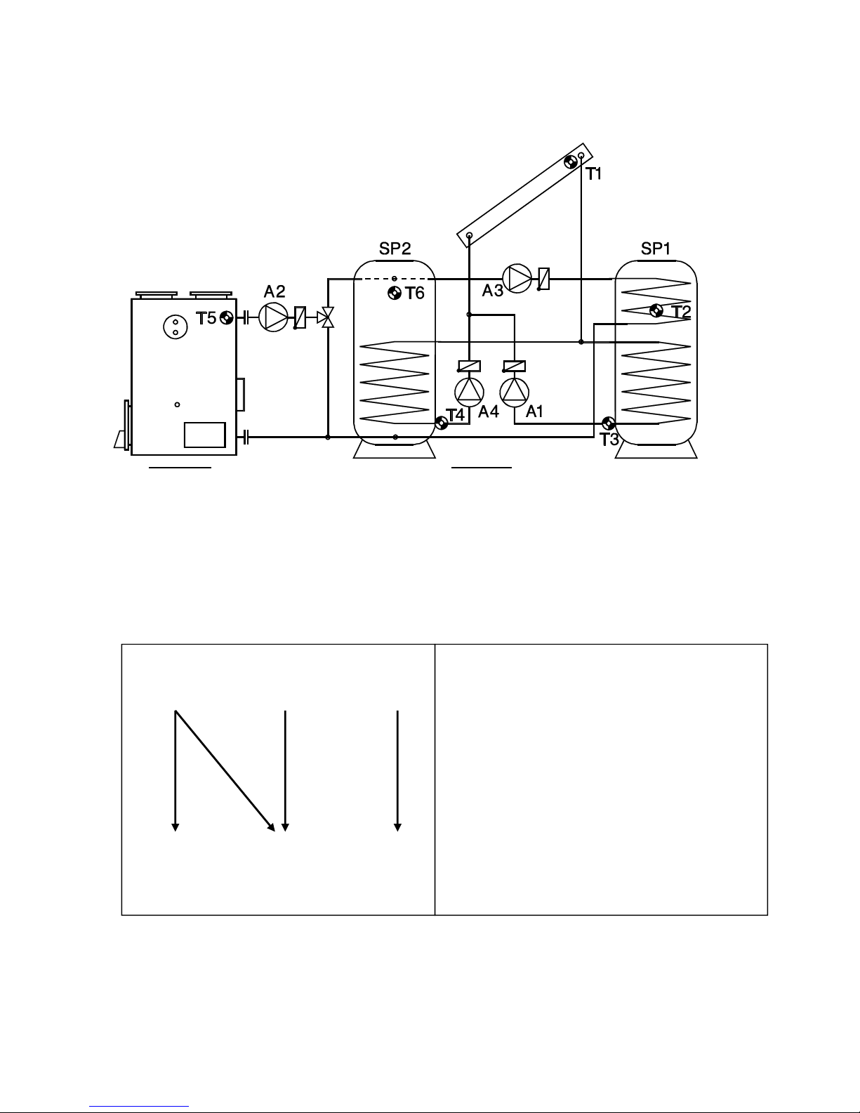
Diagram 0
7
Hydraulic diagrams
Diagram 0: Solar power system with 2 consumers and 2 feed pumps
Sensors Outputs
T1…. Collector A1…. Solar pump circuit 1
T2…. Tank 1 top A2…. Feed pump tank 2
T3…. Tank 1 bottom A3…. Feed pump tank 1
T4…. Tank 2 bottom A4…. Solar pump circuit 2
T5…. Boiler
T6…. Tank 2 top
Program 0: Function according to diagram
A1 = T1 > (T3 + diff1) & T3 < max1
A2 = T5 > (T4 + diff2) & T5 > min1 & T4 < max2
A3 = T6 > (T2 + diff3) & T6 > min2 & T2 < max3
A4 = T1 > (T4 + diff4) & T4 < max4
T1 T5 T6
min1 min2
diff1 diff4 diff2 diff3
A1 A4 A2 A3
T3 T4 T2
max1 max2 max3
max4
Required settings:
diff1 … coll. T1 – TK1 T3 A1
diff2 … boiler T5 – TK2 T4 A2
diff3 … TK2 T6 – TK1 T2 A3
diff4 … coll. T1 – TK2 T4 A4
min1 … switch-on temp. boiler T5 A2
min2 … switch-on temp. TK2 T6 A3
max1 … limit TK1 T3 A1
max2 … limit TK 2 T4 A2
max3 … limit TK 1 T2 A3
max4 … limit TK 2 T4 A4
Additional: Priority Vorr:
(typical: A11, A20, A30, A42)
TK2 TK1
Page 8

Diagram 0
8
Program 1: Instead of the two solar pumps, one pump and a three-way valve are used
(pump-valve system). The speed control (if activated) only operated when filling tank 1.
Without a priority allocation, tank 2 is filled by priority.
A1... common pump
A4... Valve (A4/S receives power when filling tank)
All programs +2: In program 0 the feed of tank TK1 by pump A3 is only controlled by differ-
ence TK2 T6 – TK1 T2. This program also includes the boiler temperature. When feeding
tank TK1 by pump A3 the difference boiler T5 – TK1 T2 will be considered additionally (same
setting diff3). Both min thresholds are active.
A1 = T1 > (T3 + diff1) & T3 < max1
A2 = T5 > (T4 + diff2) & T4 < max2 & T5 > min1
A3 = T6 > (T2 + diff3) & T2 < max3 & T6 > min2
or T5 > (T2 + diff3) & T2 < max3 & T5 > min1
A4 = T1 > (T4 + diff4) & T4 < max4
All programs +4: If both tanks have reached their maximum temperature due to the solar
power system, solar pump A1 and feed pump A3 are switched on (reverse cooling func-
tion). A3 ... or T3 > max1 & T6 < T3
All programs +8: If both tanks have reached their maximum temperature due to the solar
power system, solar pump A4 and feed pump A2 are switched on (reverse cooling function). A2 ... or T4 > max2 & T5 < T4
Note: If a solar pump is switched off manually, the controller works during reverse cooling
as the tank limit would be reached.
Program 12: The output A2 becomes available, if the feed function of tank TK2 is done by
the boiler controller. In this program A2 only switches with the thermostat function max2 at
T5 (e.g. burner requirement)
Program 13: Function like program 12, but with pump–valve system at the solar sector (see
program 1)
Program 14: Similar to Program 12. The burner requirement A2 switches on at min1 on T5.
Switch off appears when T2 has exceeded the threshold max2.
Program 15: Function like Program 14, but with pump–valve system in the solar system.
T1 T5 T6
min1 min2
diff2 diff3
diff1 A2 A3
A1 diff3
A3
diff4
A4
T3 T4 T2
max1 max2 max3
max4
Required settings:
diff1 …coll. T1 – TK1 T3 A1
diff2 …boiler T5 – TK2 T4 A2
diff3 …boiler T5 – TK1 T2 A3
TK2 T6 – TK1 T2 A3
diff4 …Coll. T1 – TK2 T4 A4
min1 …switch-on temp. boiler T5 A2,3
min2 …switch-on temp. TK2 T6 A3
max1 …limit TK1 T3 A1
max2 …limit TK2 T4 A2
max3 …limit TK1 T2 A3
max4 …limit TK2 T4 A4
Additional: Priority Vorr:
(typ
ical: A11, A20, A30, A42)
Page 9
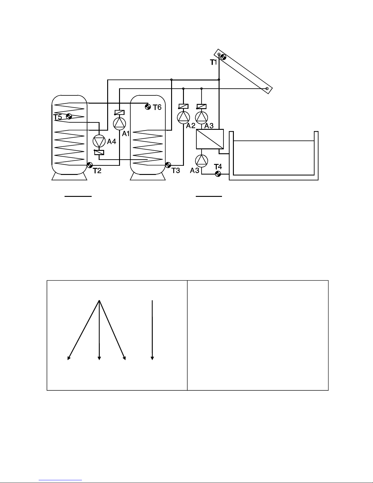
Diagram 16
9
Diagram 16: Solar power system with 3 consumers and feed pump function.
Sensors Outputs
T1…. Collector A1…. Solar pump tank TK1
T2…. Tank 1 bottom A2…. Solar pump buffer TK2
T3…. Tank 2 bottom A3…. Solar pump pool TK3
T4…. Tank 3 (pool) A4…. Feed pump
T5…. Tank 1 top
T6…. Tank 2 bottom
Program 16: Function according to diagram
A1 = T1 > (T2 + diff1) & T1 > min1 & T2 < max1
A2 = T1 > (T3 + diff2) & T1 > min1 & T3 < max2
A3 = T1 > (T4 + diff3) & T1 > min1 & T4 < max3
A4 = T6 > (T5 + diff4) & T6 > min2 & T5 < max4
T1 T6
min1 min2
diff1 diff3 diff4
A1 A3 A4
diff2
A2
T2 T3 T4 T5
max1 max2 max3 max4
Required settings:
diff1 …coll. T1 – TK1 T2 A1
diff2 …coll. T1 – TK2 T3 A2
diff3 …coll. T1 – TK3 T4 A3
diff4 …TK2 T6 – TK1 T5 A4
min1 switch-on temp. coll. T1 A1,A2,A3
min2 …switch-on temp. TK2 T6 A4
max1 …limit TK1 T2 A1
max2 …limit TK2 T3 A2
max3 …limit TK3 T4 A3
max4 …limit TK1 T5 A4
Additional: Priority Vorr:
(typical: A11, A22, A33, A40)
TK1
TK2
TK3
Page 10

Diagram 16
10
Program 17: Pump-valve system between TK1 und TK2. TK1 and TK2 are fed by a common pump A1 and a three-way valve A2. The speed control (if activated) only operated when
filling tank 1.
A1... common pump
A2... valve (A2/S receives power when filling tank TK2)
Program 18: Pump-valve system between TK1 und TK3.
A1... common pump
A3... valve (A3/S receives power when filling tank TK3)
Program 19: A common pump feeds all three tanks. Valve A3 switches between TK2 and
TK3 and – in series – valve A2 between TK1 and TK2. I.e. if both valves are free from ten-
sion, TK1 will be fed. The speed control (if activated) only operated when filling tank 1.
A1... common pump
A2... valve (A2/S receives power when filling tank TK2)
A3... valve (A3/S receives power when filling tank TK3)
If there is an active priority allocation, the two valves A2 and A3 are never switched on
simultaneously: when filling into tank 2, only pump A1 and valve A2 are switched on, when
filling into tank 3, only pump A1 and valve A3 are switched on.
All programs +4: A4 is only a signal contact which shows, that all tanks have reached their
max-thresholds.
All programs +8: If all tanks have reached their maximum temperature due to the solar
power system, tank TK2 will be fed regardless of max2.
Page 11
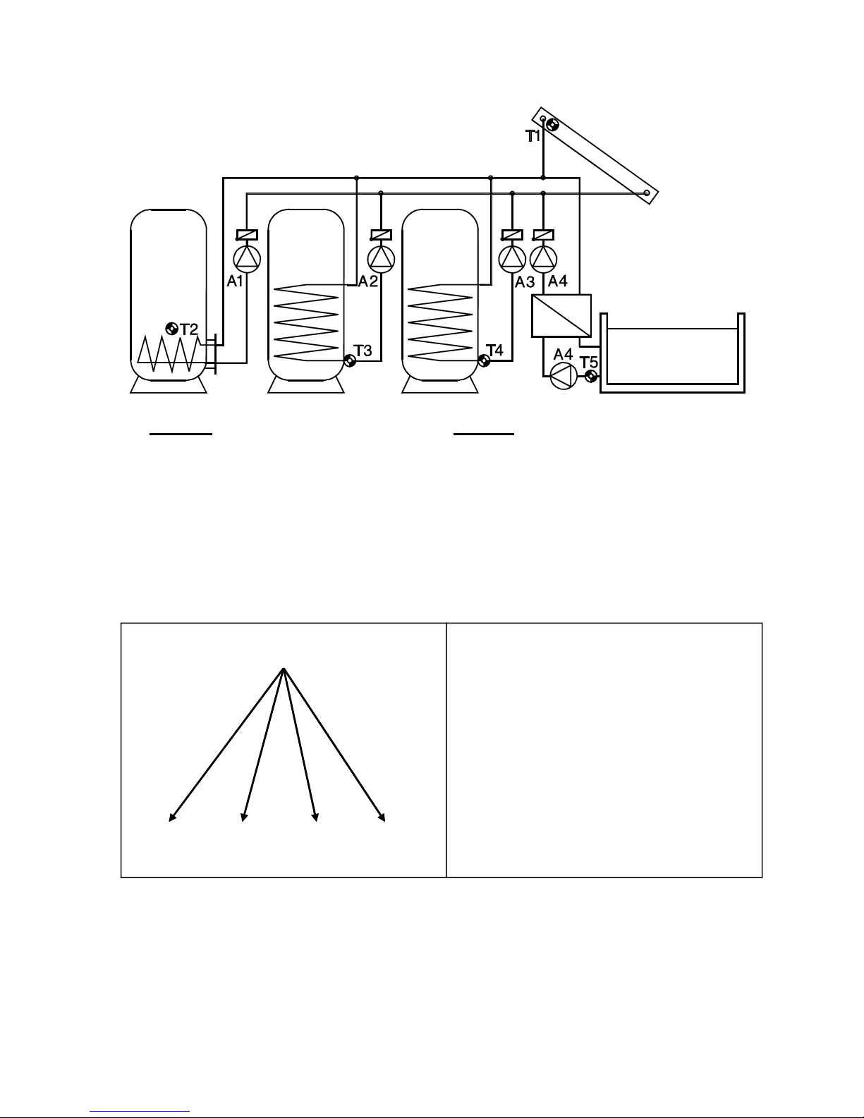
Diagram 32
11
Diagram 32: Solar power system with 4 consumers
Sensors Outputs
T1…. Collector A1…. Solar pump TK1
T2…. Tank 1 (TK1) A2…. Solar pump buffer TK2
T3…. Tank 2 (TK2) A3…. Solar pump buffer TK3
T4…. Tank 3 (TK3) A4…. Solar pump pool TK4
T5…. Tank 4 (pool TK4)
T6…. Freely usable
Program 32: Function according to diagram
A1 = T1 > (T2 + diff1) & T1 > min1 & T2 < max1
A2 = T1 > (T3 + diff2) & T1 > min1 & T3 < max2
A3 = T1 > (T4 + diff3) & T1 > min1 & T4 < max3
A4 = T1 > (T5 + diff4) & T1 > min1 & T5 < max4
T1
min1
diff1 diff4
A1 A4
diff2 diff3
A2 A3
T2 T3 T4 T5
max1 max2 max3 max4
Required settings:
diff1 …coll. T1 – TK1 T2 A1
diff2 …coll. T1 – TK 2 T3 A2
diff3 …coll. T1 – TK 3 T4 A3
diff4 …coll. T1 – TK 4 T5 A4
min1 …switch-on temp. coll. T1 A1,
A2, A3, A4
max1 …limit TK 1 T2 A1
max2 …limit TK 2 T3 A2
max3 …limit TK 3 T4 A3
max4 …limit TK 4 T5 A4
Additional: Priority Vorr:
(typical: A11, A22, A33, A44)
TK1 TK2 TK3
TK4
Page 12

Diagram 32
12
Program 33: Pump-valve system between TK1 und TK2. TK1 and TK2 are fed by a common pump A1 and a three-way valve A2. The speed control (if activated) only operated when
filling tank 1.
A1... common pump
A2... valve (A2/S receives power when filling tank TK2)
All programs +2: Pump-valve system between TK1 und TK3.
A1... common pump
A3... valve (A3/S receives power when filling tank TK3)
All programs +4: Pump-valve system between TK1 und TK4.
A1... common pump
A4... valve (A4/S receives power when filling tank TK4)
All programs +8: If all tanks have reached their maximum temperature due to the solar
power system, tank TK2 will be fed regardless of max2.
Page 13
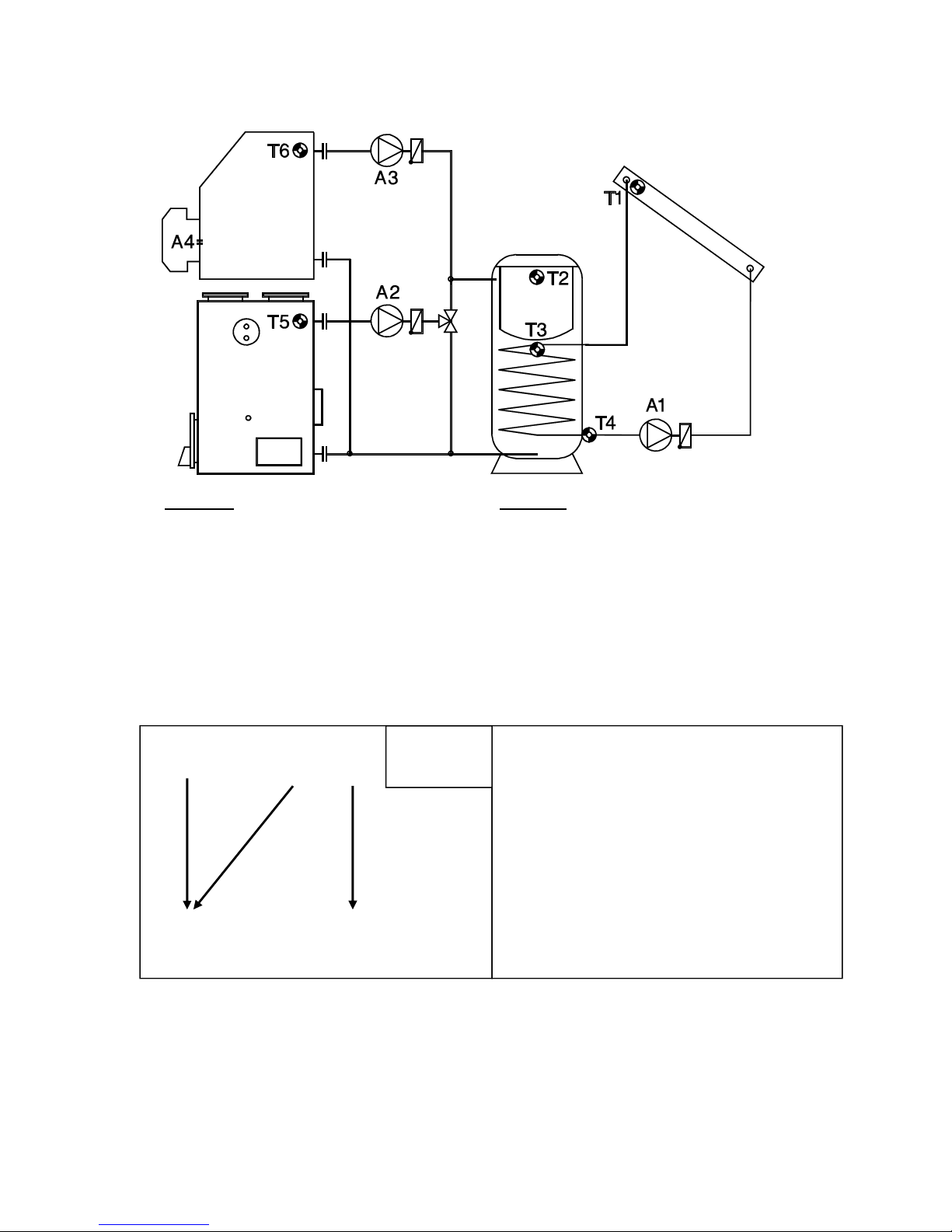
Diagram 48
13
Diagram 48: Burner requirement, 2 feed pumps and simple solar power unit
Sensors Outputs
T1…. Collector A1…. Solar pump
T2…. Tank top A2…. Feed pump solid fuel boiler
T3…. Tank center A3…. Feed pump oil/gas boiler
T4…. Tank bottom A4…. Burner requirement
T5…. Solid fuel boiler (“sfb”)
T6…. Oil/gas boiler (“ogb”)
Program 48: Function according to diagram
A1 = T1 > (T4 + diff1) & T4 < max1
A2 = T5 > (T4 + diff2) & T5 > min1 & T4 < max2
A3 = T6 > (T3 + diff3) & T6 > min2 & T3 < max3
A4 (on) = T2 < max4 – hysteresis
A4 (off) = T2 > max4
T1 T5 T6
min1 min2
diff1
A1 diff2 diff3
A2 A3
T4 T3
max1 max3
max2
Required settings:
diff1 …coll. T1 – TK T4 A1
diff2 …sf-boiler T5 – TK T4 A2
diff3 …oil boiler T6 – TK T3 A3
diff4 …see all programs +8
min1 …switch-on temp. sfb T5 A2
min2 …switch-on temp. ogb T6 A3
max1 …limit TK T4 A1
max2 …limit TK T4 A2
max3 …limit TK T3 A3
max4 …burner requirement TK T2 A4
Burner A4
T2 max4
Burner
requirement
Page 14
Diagram 48
14
Program 49: If the tank has reached its maximum temperature due to the solar power system, solar pump A1 and feed pump A2 are switched on (reverse cooling function).
A2 ... or T4 > max1 & T5 < T4
All Programs +2: Output A4 (burner requirement) switches on when T2 falls below threshold
max4 and switches off when T3 exceeds max3. Max3 is no longer the tank limit for the
oil/gas boiler feed pump.
A1 = T1 > (T4 + diff1) & T4 < max1
A2 = T5 > (T4 + diff2) & T5 > min1 & T4 < max2
A3 = T6 > (T3 + diff3) & T6 > min2
A4 (on) = T2 < max4 – hysteresis
A4 (off) = T3 > max3
All Programs +4: Three independent differential loops. The tank feeding A2 from the solid
fuel boiler is controlled by the difference diff2 between boiler sensor T5 and the sensor T2
(tank top)
A1 = T1 > (T4 + diff1) & T4 < max1
A2 = T5 > (T2 + diff2) & T5 > min1 & T2 < max2
A3 = T6 > (T3 + diff3) & T6 > min2 & T3 < max3
A4 (on) = T2 < max4 – hysteresis
A4 (off) = T2 > max4
T1 T5 T6
min1 min2
diff1
A1 diff2 diff3
A2 A3
T4 T3
max1
max2
Required settings:
diff1 …coll. T1 – TK T4 A1
diff2 …sf-boiler T5 – TK T4 A2
diff3 …oil boiler T6 – TK T3 A3
min1 …switch-on temp. sfb T5 A2
min2 …switch-on temp. ogb T6 A3
max1 …limit TK T4 A1
max2 …limit TK T4 A2
max3 …burner requ. OFF TK T3 A4
max4 …burner requ. ON TK T2 A4
Burner A4
T2 max4
T3 max3
T1 T5 T6
min1 min2
diff1 diff2 diff3
A1 A2 A3
T4 T2 T3
max1 max2 max3
Required settings:
diff1 …coll. T1 – TK T4 A1
diff2 …sf-boiler T5 – TK T2 A2
diff3 …oil boiler T6 – TK T3 A3
min1 …switch-on temp. sfb T5 A2
min2 …switch-on temp. ogb T6 A3
max1 …limit TK T4 A1
max2 …limit TK T2 A2
max3 …limit TK T3 A3
max4 …burner requirement TK T2 A4
Burner A4
T2 max4
Page 15
Diagram 48
15
All Programs +8: This program enables controlling of two generators to each one consumer.
Output A4 is switched with the difference diff4 between T2 and T3 instead of burner requirement. T2 is available for an additional forth generator. In this case threshold max4 operates at T3.
A1 = T1 > (T4 + diff1) & T4 < max1
A2 = T5 > (T4 + diff2) & T5 > min1 & T4 < max2
A3 = T6 > (T3 + diff3) & T6 > min2 & T3 < max3
A4 = T2 > (T3 + diff4) & T3 < max4
Program 60: The whole function offers switching of two generators to one consumer and one
generator to two consumers. Output A4 gets an additional difference function instead of
burner requirement. A4 switches, if sensor T6 is increasing min2 and is greater than T2 by
diff4 and T2 has not exceeded max4.
A1 = T1 > (T4 + diff1) & T4 < max1
A2 = T5 > (T4 + diff2) & T5 > min1 & T4 < max2
A3 = T6 > (T3 + diff3) & T6 > min2 & T3 < max3
A4 = T6 > (T2 + diff4) & T6 > min2 & T2 < max4
T1 T5 T6 T2
min1 min2
diff1
A1 diff2 diff3 diff4
A2 A3 A4
T4 T3
max1 max3
max2 max4
Required settings:
diff1 …coll. T1 – TK T4 A1
diff2 …sf-boiler T5 – TK T4 A2
diff3 …oil boiler T6 – TK T3 A3
diff4 …generator T2 – TK T3 A4
min1 …switch-on temp. sfb T5 A2
min2 …switch-on temp. ogb T6 A3
max1 …limit TK T4 A1
max2 …limit TK T4 A2
max3 …limit TK T3 A3
max4 …limit TK T3 A4
T1 T5 T6
min1 min2
diff1
A1 diff2 diff3 diff4
A2 A3 A4
T4 T3 T2
max1 max3 max4
max2
Required settings:
diff1 …coll. T1 – TK T4 A1
diff2 …sf-boiler T5 – TK T4 A2
diff3 …oil boiler T6 – TK T3 A3
diff4 …oil boiler T6 – TK T2 A4
min1 …switch-on temp. sfb T5 A2
min2 …switch-on temp. ogb T6 A3,4
max1 …limit TK T4 A1
max2 …limit TK T4 A2
max3 …limit TK T3 A3
max4 …limit TK T2 A4
Page 16
Diagram 48
16
Program 61: Function similar to Program 60, but output A3 does not only switch by the origin
function, but additionally, if T5 is increasing min1 and is greater than T3 by diff3
A1 = T1 > (T4 + diff1) & T4 < max1
A2 = T5 > (T4 + diff2) & T5 > min1 & T4 < max2
A3 = T6 > (T3 + diff3) & T6 > min2 & T3 < max3
or T5 > (T3 + diff3) & T5 > min1 & T3 < max3
A4 = T6 > (T2 + diff4) & T6 > min2 & T2 < max4
Program 62: Additionally to program 60 output A4 switches, if T5 is increasing min1 and is
greater than T2 by diff4.
A1 = T1 > (T4 + diff1) & T4 < max1
A2 = T5 > (T4 + diff2) & T5 > min1 & T4 < max2
A3 = T6 > (T3 + diff3) & T6 > min2 & T3 < max3
A4 = T6 > (T2 + diff4) & T6 > min2 & T2 < max4
or T5 > (T2 + diff4) & T5 > min1 & T2 < max4
T1 T5 T6
min1 min2
diff1
A1 diff2 diff4
A2 A4
diff3 diff3
A3 A3
T4 T3 T2
max1 max3 max4
max2
Required settings:
diff1 …coll. T1 – TK T4 A1
diff2 …sf-boiler T5 – TK T4 A2
diff3 …oil boiler T6 – TK T3 A3
diff3 …sf-boiler T5 – TK T3 A3
diff4 …oil boiler T6 – TK T2 A4
min1 …switch-on temp. sfb T5 A2,3
min2 …switch-on temp. ogb T6 A3,4
max1 …limit solar TK T4 A1
max2 …limit TK T4 A2
max3 …limit TK T3 A3
max4 …limit TK T2 A4
T1 T5 T6
min1 min2
diff1
A1 diff2 diff4
A2 A4
diff3
A3 diff4
A4
T4 T3 T2
max1 max3 max4
max2
Required settings:
diff1 …coll. T1 – TK T4 A1
diff2 …sf-boiler T5 – TK T4 A2
diff3 …oil boiler T6 – TK T3 A3
diff4 …oil boiler T5 – TK T2 A4
sf-boiler T6 – TK T2 A4
min1 …switch-on temp. sfb T5 A2,4
min2 …switch-on temp. ogb T6 A3,4
max1 …limit TK T4 A1
max2 …limit TK T4 A2
max3 …limit TK T3 A3
max4 …limit TK T2 A4
Page 17
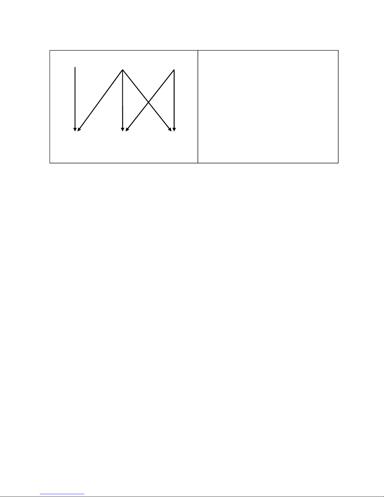
Diagram 48
17
Program 63: Output A3 switches as described in program 61 and A4 as per program 62.
A1 = T1 > (T4 + diff1) & T4 < max1
A2 = T5 > (T4 + diff2) & T5 > min1 & T4 < max2
A3 = T5 > (T3 + diff3) & T5 > min1 & T3 < max3
or T6 > (T3 + diff3) & T6 > min2 & T3 < max3
A4 = T5 > (T2 + diff4) & T5 > min1 & T2 < max4
or T6 > (T2 + diff4) & T6 > min2 & T2 < max4
T1 T5 T6
min1 min2
diff4
diff1 A4
A1 diff2
A2 diff4
diff3 A4
A3
diff3
A3
T4 T3 T2
max1 max3 max4
max2
Required settings:
diff1 …col. T1 – TK T4 A1
diff2 …boiler T5 – TK T4 A2
diff3 …boiler T5 – TK T3 A3
…boiler T6 – TK T3 A3
diff4 …boiler T5 – TK T2 A4
…boiler T6 – TK T2 A4
min1 …switch-on temp. T5 A2,3,4
min2 …switch-on temp. T6 A3,4
max1 …limit TK T4 A1
max2 …limit TK T4 A2
max3 …limit TK T3 A3
max4 …limit TK T2 A4
Page 18
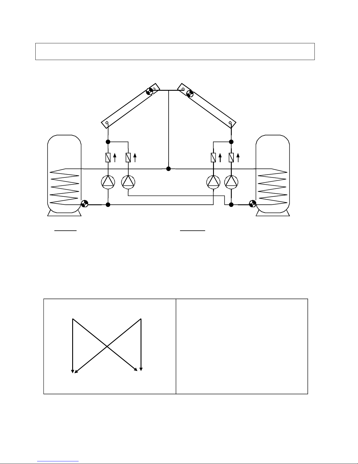
Diagram 64
18
T1 T2
SP 2
A4 A3
SP 1
A2 A1
T4 T3
Diagram 64: Solar power system with two solar panels and two consumers
Note: Setting the time switch, the definition of the output corresponds to the actual output,
but setting the priority it corresponds to the basic function of program 64.
Program 64: Each tank is fed from each solar panel by 4 separate pumps. No feed pump
function!
Sensor Outputs
T1…. Collector 1 A1…. Pump collector 1 – TK1
T2…. Collector 2 A2…. Pump collector 1 – TK2
T3…. Tank 1 bottom A3…. Pump collector 2 – TK1
T4…. Tank 2 bottom A4…. Pump collector 2 – TK2
T5…. Freely usable
T6…. Freely usable
Program 64: Function according to diagram
A1 = T1 > (T3 + diff1) & T3 < max1
A2 = T1 > (T4 + diff2) & T4 < max2
A3 = T2 > (T3 + diff1) & T3 < max1
A4 = T2 > (T4 + diff2) & T4 < max2
T1 T2
diff1 diff2 diff2
A1 A2 A4
diff1
A3
T3 T4
max1 max2
Required settings:
diff1 …coll. T1 – TK1 T3 A1
coll. T2 – TK1 T3 A3
diff2 …coll. T1 – TK2 T4 A2
coll. T2 – TK2 T4 A4
diff3 …see all programs +1
max1 …limit TK1 T3 A1,3
max2 …limit TK2 T4 A2,4
Additional: Priority Vorr:
(typical: A11, A22, A31, A42)
TK 2 TK 1
Page 19
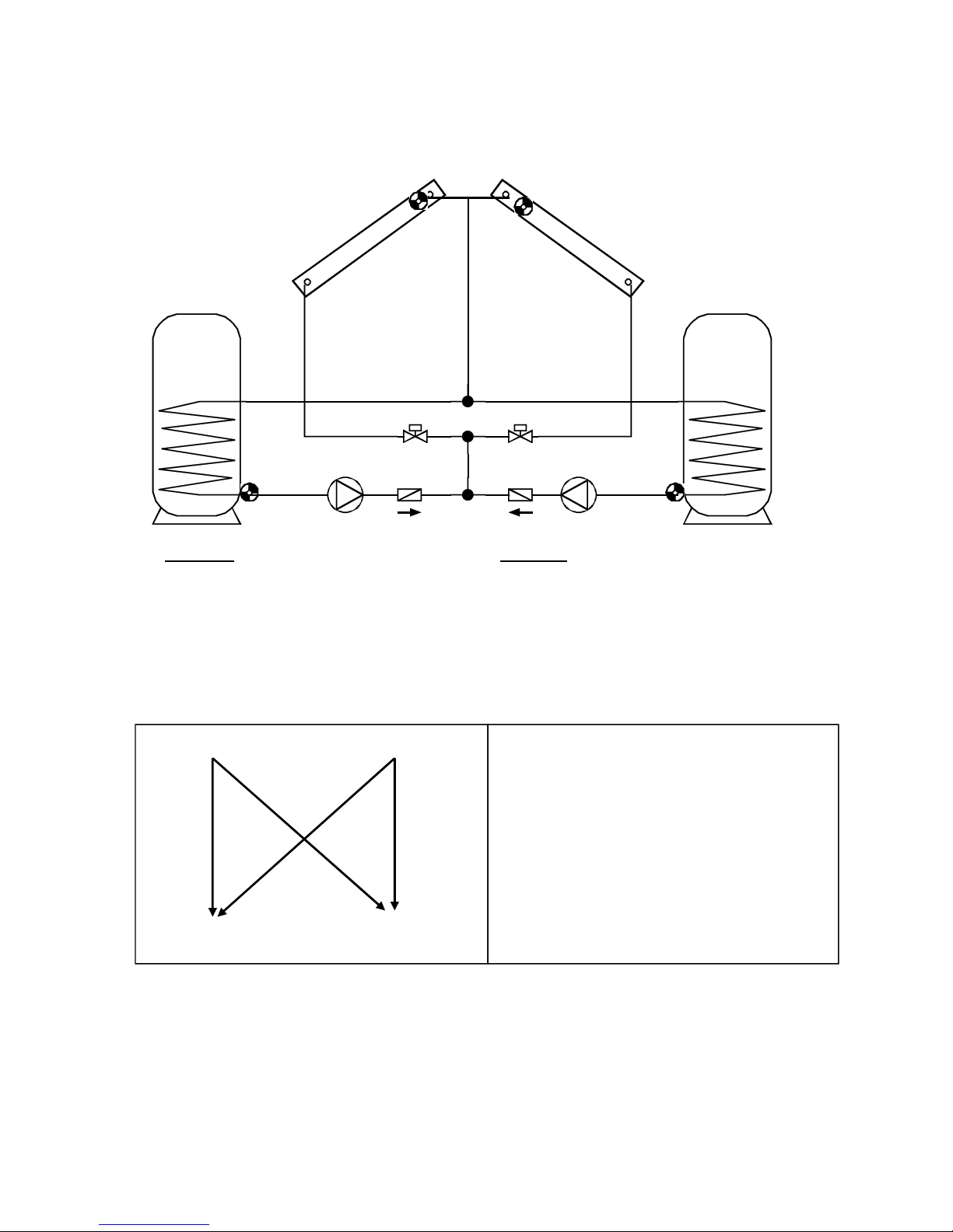
Diagram 64
19
T1 T2
SP 2
SP 1
T4 T3
A3 A4
A2 A1
Program 66: 2 stop valves and 2 pumps instead of the 4 pumps in program 64. No feed
pump function!
Attention! If both valves are closed, both pumps will be switched off.
Sensors Outputs
T1…. Collector 1 A1…. Pump TK1
T2…. Collector 2 A2…. Pump TK2
T3…. Tank 1 bottom A3…. Valve Collector panel 1
T4…. Tank 2 bottom A4…. Valve Collector panel 2
T5…. Freely usable
T6…. Freely usable
A1 & A3 = T1 > (T3 + diff1) & T3 < max1
A1 & A4 = T2 > (T3 + diff1) & T3 < max1
A2 & A3 = T1 > (T4 + diff2) & T4 < max2
A2 & A4 = T2 > (T4 + diff2) & T4 < max2
A system of one pump and a three-way valve instead of two pumps can be realized by us-
ing the auxiliary output A5: Pump = A1, three-way valve = A2; the auxiliary output A5 switches simultaneously with A2 the pump A1 (setting: A2o).
T1 T2
diff1 diff2 diff2
A1,A3 A2,A3 A2,A4
diff1
A1,A4
T3 T4
Required settings:
diff1 …coll. T1 – TK1 T3 A1,3
coll. T2 – TK1 T3 A1,4
diff2 …coll. T1 – TK2 T4 A2,3
coll. T2 – TK2 T4 A2,4
diff3 …see all programs +1
max1 …limit TK1 T3 A1,3,4
max2 …limit TK2 T4 A2,3,4
Additional: Priority Vorr:
(typical: A11, A22, A31, A42)
TK 2 TK 1
Page 20

Diagram 64
20
Program 68: Function according to diagram.
The three-way valve A3 receives power when filling tank TK2.
Sensors Outputs
T1…. Collector 1 A1…. Solar pump collector panel 1
T2…. Collector 2 A2…. Solar pump collector panel 2
T3…. Tank 1 bottom A3…. Three-way valve (feeding tanks)
T4…. Tank 2 bottom A4…. Feed pump
T5…. Tank 1 top
T6…. Tank 2 top
A1 = T1 > (T3 + diff1) & T3 < max1
A1 & A3 = T1 > (T4 + diff2) & T4 < max2
A2 = T2 > (T3 + diff1) & T3 < max1
A2 & A3 = T2 > (T4 + diff2) & T4 < max2
A4 = T6 > (T5 + diff4) & T6 > min2 & T5 < max4
All Programs +1: If the difference between collector sensors T1 and T2 exceeds the difference diff3, the colder collector is switched off. This prevents heat from being lost in the colder collector when temperatures are mixed.
T1 T2 T6
min2
diff1 diff2 diff2 diff4
A1 A1,3 A2,3 A4
diff1
A2
T3 T4 T5
max1 max2 max4
Required settings:
diff1 …coll. T1 – TK1 T3 A1
coll. T2 – TK1 T3 A2
diff2 …coll. T1 – TK2 T4 A1,3
coll. T2 – TK2 T4 A2,3
diff3 …see all programs +1
diff4 …TK2 T6 – TK1 T5 A4
min2 …switch-on temp. T6 A4
max1 …limit TK1 T3 A1,2
max2 …limit TK2 T4 A1,2,3
max4 …limit TK1 T5 A4
Additional: Priority Vorr:
(typical: A11, A22, A31, A42)
TK 2 TK 1
Page 21

Diagram 80
21
Diagram 80: Layering storage tank, feed pump and domestic hot water preparation
Sensors Outputs
T1…. Collector A1…. Solar pumps
T2…. Tank top A2…. Heat exchanger pump (hot water)
T3…. Tank bottom A3…. Three-way valve layering storage
T4…. Hot water (ultra-fast sensor) A4…. Feed pump
T5…. Boiler
T6…. Solar flow
Program 80: Function according to diagram
A1 = T1 > (T3 + diff1) & T3 < max1
A2 = T2 > (T4 + diff2) & T4 < max2
A3 = (T6 > min2 or T6 > (T2 + diff3)) & T2 < max3
A4 = T5 > (T3 + diff4) & T5 > min1 & T3 < max4
T1 T5 T6 T6
min1 min2
diff1 diff4 diff3
A1 A4 A3 A3
T3 T2
max1 max3
max4
diff2
A2
T4
max2
Required settings:
diff1 …coll. T1 – TK T3 A1
diff2 …tank T2 – WW T4 A2
diff3 …flow T6 – TK T2 A3
diff4 …boiler T5 – TK T3 A4
min1 …switch-on temp. boiler T5 A4
min2 …switch-on temp. flow T6 A3
max1 …limit TK T3 A1
max2 …limit WW T4 A2
max3 …threshold TK T2 A3
max4 …limit feed pump TK T3 A4
Additional: Both speed controls Pd1,
Pd2
CW
Page 22

Diagram 80
22
Program 80: Function according to diagram
Both solar pumps are switched on by the difference diff1. The three-way valve A3 switches
to the tank top, when T6 is increasing min2 or is greater than T2 by diff3, but T2 has not exceeded the threshold max3.
The speed controlled output A2 is used for domestic hot water preparation. The detection of
a flow is possible by using a volume flow switch, electrically switched in series to sensor T4.
Sensor T4 is kept constant by the speed control (absolute value control). When T2 decreases, the controller keeps the difference between T2 and T4 constant (setting of the value d in
menu speed control) for avoiding the mixing inside the tank because of too high pump speed
(differential control). The slower of the two speeds “wins out”.
Program 81: If T2 has reached max3, the quick warm-up phase has been completed, and
the speed control for A1 is thus blocked optimal efficiency.
Program 82: The speed control for A1 is blocked, when the three-way valve switches to the
bottom (A3 = off). In this case the priority control is active for the possibility of switching back
to the top tank area at high enough solar radiation.
All Programs +4: The domestic hot water preparation is not applicable. A2 is the secondary
pump in the solar loop. T4 should be mounted in the primary solar loop. A2 switches, when
A1 is already active and T4 is greater than T3 by diff2.
A1 = T1 > (T3 + diff1) & T3 < max1
A2 = T4 > (T3 + diff2) & (A1 = on)
A3 = (T6 > min2 or T6 > (T2 + diff3)) & T2 < max3
A4 = T5 > (T3 + diff4) & T5 > min1 & T3 < max4
T4 T1 T5 T6 T6
min1 min2
diff2 diff1 diff4 diff3
A2 A1 A4 A3 A3
& A1 ein
T3 T2
max1 max3
max4
Required settings:
diff1 …coll. T1 – TK T3 A1
diff2 …solar flow T4 – TK T3 A2
diff3 …flow T6 – TK T2 A3
diff4 …boiler T5 – TK T3 A4
min1 …switch-on temp. boiler T5 A4
min2 …switch-on temp. flow T6 A3
max1 …limit TK T3 A1
max3 …threshold. TK T2 A3
max4 …limit. feed pump TK T3 A4
Additional: Both speed controls Pd1,
Pd2
Page 23

Diagram 80
23
Program 88: A1 gets additionally the threshold min1 at T1. The solid fuel boiler is not appli-
cable. The domestic hot water preparation by A2 is also switching, if T4 is greater than T5 by
diff2. T5 could be a volume flow switch. A4 is used for burner requirement. A4 switches
when T2 has not exceeded max4.
A1 = T1 > min1 & T1 > (T3 + diff1) & T3 < max1
A2 = T4 > (T5 + diff2) or (T2 > 50°C & T4 < max2)
A3 = (T6 > min2 or T6 > (T2 + diff3)) & T2 < max3
A4 (on) = T2 < max4 – hysteresis
A4 (off) = T2 > max4
Program 89: according to program 88, but: If T4 has reached max3, the quick warm-up
phase has been completed, and the speed control of A1 is thus blocked optimal efficiency.
Program 92: according to program 88, but: the changing between tank center and top is
done by a thermic valve. Therefore A3 is free for an additional feed pump function. A3
switches when T6 is increasing min2 and is greater than T3 by diff3 and T3 has not exceeded max3.
A1 = T1 > min1 & T1 > (T3 + diff1) & T3 < max1
A2 = T4 > (T5 + diff2) or (T2 > 50°C & T4 < max2)
A3 = T6 > min2 & T6 > (T3 + diff3) & T3 < max3
A4 (on) = T2 < max4 – hysteresis
A4 (off) = T2 > max4
Program 94: according to program 92, but: the sensor T2 in the tank top is used for the feed
pump function A3. Therefore this function is better suitable for oil or gas boilers.
A1 = T1 > min1 & T1 > (T3 + diff1) & T3 < max1
A2 = T4 > (T5 + diff2) or (T2 > 50°C & T4 < max2)
A3 = T6 > min2 & T6> (T2 + diff3) & T2 < max3.
A4 (on) = T2 < max4 – hysteresis
A4 (off) = T2 > max4
T1 T6 T6 T4 A2 off
min1 min2 T2 < 50°C
diff1 diff3 diff2
A1 A3 A2 A2 on
A3
T3 T2 T5 A2 on
max1 max3 T4 > max2
Required settings:
diff1 …coll. T1 – TK T3 A1
diff2 …sensor T4 – sensor T5 A2
diff3 …flow T6 – TK T2 A3
min1 …switch-on temp. coll. T1 A2
min2 …switch-on temp. flow T6 A3
max1 …limit TK T3 A1
max2 …limit WW T4 A2
max3 …threshold TK T2 A3
max4 …burner requirement T2 A4
Additional: Both speed controls Pd1,
Pd2
Burner A4
T2 max4
Page 24

Diagram 96
24
Diagram 96: Solar power system with two consumers and two feed pump functions
Sensors Outputs
T1…. Collector A1…. Solar pump loop 1
T2…. Tank TK1 top A2…. Feed pump TK2
T3…. Tank TK1 center A3…. Feed pump TK3
T4…. Tank TK1 bottom A4…. Solar pump loop 2
T5…. Tank TK2 bottom
T6…. Tank TK3 bottom
Program 96: Function according to diagram.
A1 = T1 > (T3 + diff1) & T1 > min1 & T3 < max1
A2 = T2 > (T5 + diff2) & T2 > min2 & T5 < max2
A3 = T2 > (T6 + diff3) & T2 > min2 & T6 < max3
A4 = T1 > (T4 + diff4) & T1 > min1 & T4 < max4
T1 T2
min1 min2
diff1 diff2 diff3
A1 A2 A3
diff4
A4
T3 T4 T5 T6
max1 max4 max2 max3
Required settings:
diff1 …coll. T1 – TK1 T3 A1
diff2 …TK 1 T2 – TK 2 T5 A2
diff3 …TK 1 T2 – TK 3 T6 A3
diff4 …Coll. T1 – TK 1 T4 A4
min1 …switch-on temp. coll. T1 A1,4
min2 …switch-on temp. TK 1 T2 A2,3
max1 …limit TK1 T3 A1
max2 …limit TK2 T5 A2
max3 …limit TK3 T6 A3
max4 …limit TK1 T4 A4
Additional: Priority Vorr:
(typical: A11, A20, A30, A42)
TK1
TK2 TK3
Page 25

Diagram 96
25
Program 97: Instead of the two solar pumps, one pump and a three-way valve are used
(pump-valve system). The speed control (if activated) only operated when filling loop 1 (T3).
A1... common pump
A4... Valve (A4/S receives power when filling tank TK1 bottom)
All Programs +2: Instead of the two feed pumps, one pump and a three-way valve are used
(pump-valve system). The speed control (if activated) only operated when filling loop TK2
(T5).
A2... common pump
A3... Valve (A3/S receives power when filling tank TK3)
Page 26

Diagram A0
26
Diagram A0: Solar system with two consumers, feed pump, burner requirement
Sensors Outputs
T1…. Collector A1…. Solar pump loop 1
T2…. Tank TK1 top A2…. Solar pump loop 2
T3…. Tank TK1 bottom A3…. Feed pump TK1
T4…. Tank TK2 bottom A4…. Feed pump TK2
T5…. Boiler
T6…. Tank TK2 top
Program A0: Function according to diagram.
A1 = T1 > (T3 + diff1) & T3 < max1
A2 = T1 > (T4 + diff2) & T4 < max2
A3 = T6 > (T2 + diff3) & T6 > min2 & T2 < max3
A4 = T5 > (T6 + diff4) & T5 > min1 & T6 < max4
T1 T5
min1
diff1 diff2 diff4
A1 A2 A4
T6
T3 T4 max4
max1 max2 min2
diff3
A3
T2
max3
Required settings:
diff1 …coll. T1 – TK1 T3 A1
diff2 …coll. T1 – TK2 T4 A2
diff3 …TK2 T6 – TK1 T2 A3
diff4 …boiler T5 – TK2 T6 A4
min1 …switch-on temp. boiler T5 A4
min2 …switch-on temp. TK2 T6 A3
max1 …limit TK1 T3 A1
max2 …limit TK2 T4 A2
max3 …limit TK1 T2 A3
max4 …limit TK2 T6 A4
Additional: Priority Vorr:
(typical: A11, A22, A30, A40)
TK2 TK1
Page 27

Diagram A0
27
All Programs +1: Instead of the two solar pumps, one pump and a three-way valve are used
(pump-valve system). The speed control (if activated) only operated when filling TK 1 (T3).
A1... common pump
A2... Valve (A2/S receives power when filling tank TK2)
All Programs +2: Output A4 is used for burner requirement with separated on and off
thresholds instead of feed pump function.
A1 = T1 > (T3 + diff1) & T3 < max1
A2 = T1 > (T4 + diff2) & T4 < max2
A3 = T6 > (T2 + diff3) & T6 > min2 & T2 < max3
A4 (on) = T6 < min1 A4 (off) = T5 > max4
Program A4: The feed pump function of output A4 is active between boiler T5 and tank 1 T2.
A1 = T1 > (T3 + diff1) & T3 < max1
A2 = T1 > (T4 + diff2) & T4 < max2
A3 = T6 > (T2 + diff3) & T6 > min2 & T2 < max3
A4 = T5 > (T2 & diff4) & T5 > min1 & T2 < max4
Program A6: Burner requirement A4 (on), when T5 < min1
Burner requirement A4 (off), when T2 > max4
A1 = T1 > (T3 + diff1) & T3 < max1
A2 = T1 > (T4 + diff2) & T4 < max2
A3 = T6 > (T2 + diff3) & T6 > min2 & T2 < max3
A4 (on) = T5 < min1 A4 (off) = T2 > max4
T1 T6
min2
diff1 diff2 diff3
A1 A2 A3
T3 T4 T2
max1 max2 max3
Required settings:
diff1 …coll. T1 – TK1 T3 A1
diff2 …coll. T1 – TK2 T4 A2
diff3 …TK2 T6 – TK1 T2 A3
min1 …burner requ. ON T6 A4
min2 …switch-on temp. TK2 T6 A3
max1 …limit TK1 T3 A1
max2 …limit TK2 T4 A2
max3 …limit TK1 T2 A3
max4 …burner requ. OFF T5 A4
Additional: Priority Vorr:
(typical: A11, A22, A30, A40)
Burner A4
T6 min1
T5 max4
Page 28

Diagram B0
28
Diagram B0: Solar power system, 2 feed pump functions, burner requirement
Sensors Outputs
T1…. Collector A1…. Solar pump
T2…. Tank TK2 bottom A2…. Feed pump TK2
T3…. Tank TK1 center A3…. Feed pump TK1
T4…. Tank TK1 bottom A4…. Burner requirement
T5…. Tank TK1 top
T6…. Boiler
Program B0: Function according to diagram.
A1 = T1 > (T4 + diff1) & T4 < max1
A2 = T5 > (T2 + diff2) & T5 > min1 & T2 < max2
A3 = T6 > (T3 + diff3) & T6 > min2 & T3 < max3
A4 (on) = T5 < max4 – hysteresis
A4 (off) = T5 > max4
T1 T5 T6
min1 min2
diff1 diff2 diff3
A1 A2 A3
T4 T2 T3
max1 max2 max3
Required settings:
diff1 …coll. T1 – TP1 T4 A1
diff2 …TK1 top T5 – TK2 T2 A2
diff3 …boiler T6 – TK1 T3 A3
diff4 …see all programs +1
min1 …switch-on temp. TK1 T5 A2
min2 …switch-on temp. boiler T6 A3
max1 …limit TK1 T4 A1
max2 …limit TK2 T2 A2
max3 …limit TK1 T3 A3
max4 …burner requirement T5 A4
Burner A4
T5 max4
Burner
requirement
TK1 TK2
Page 29

Diagram B0
29
All Programs +1: The feeding of the hot water tank is normally done by the difference buffer
T5 – hot water tank T2. This program considers also the boiler temperature T6.
A1 = T1 > (T4 + diff1) & T4 < max1
A2 = T5 > (T2 + diff2) & T2 < max2 & T5 > min1
or T6 > (T2 + diff4) & T2 < max2 & T6 > min2
A3 = T6 > (T3 + diff3) & T3 < max3 & T6 > min2
A4 (on) = T5 < max4 – hysteresis
A4 (off) = T5 > max4
All Programs +2: Separated on and off thresholds for the burner requirement
A3 = T6 > (T3 + diff3) & T6 > min2
A4 (on) = T5 < max3
A4 (off) = T3 > max4
All Programs +4: Diagram with solid fuel boiler instead of a solar power system. The threshold min1 affects not at T5 but at T1.
T1 T5 T6
min1 min2
diff1 diff2 diff4 diff3
A1 A2 A2 A3
T4 T2 T3
max1 max2 max3
Required settings:
diff1 …coll. T1 – TP1 T4 A1
diff2 …TK1 top T5 – TK2 T2 A2
diff3 …boiler T6 – TK1 T3 A3
diff4 …boiler T6 – TK2 T2 A2
min1 …switch-on temp. TK1 T5 A2
min2 …switch-on temp. boiler T6 A2, 3
max1 …limit TK1 T4 A1
max2 …limit TK2 T2 A2
max3 …limit TK1 T3 A3
max4 …burner requirement T5 A4
Burner A4
T5 max4
Page 30

Diagram C0
30
Diagram C0: Solar power system with 3 consumers, bypass function
Sensors Outputs
T1…. Flow solar loop A1…. Primary solar pump
T2…. Tank TK1 A2…. Solar pump TK1
T3…. Tank TK2 A3…. Solar pump TK2
T4…. Tank Tk3 A4…. Solar pump TK3
T5…. Freely usable
T6…. Collector
Program C0: Function according to diagram. The primary and the secondary side are sepa-
rated hydraulically. The secondary pumps are switched separated from the primary pumps.
A1 = (T6 > (T2 + diff1) or T6 > (T3 + diff1) or T6 > (T4 + diff1))
& T6 > min2 & (T2 < max2 or T3 < max3 or T4 < max4)
A2 = T1 > (T2 + diff2) & T1 > min1 & T2 < max2
A3 = T1 > (T3 + diff3) & T1 > min1 & T3 < max3
A4 = T1 > (T4 + diff4) & T1 > min1 & T4 < max4
T6 T1
min2 min1
diff1 diff1 diff2 diff4
A1 A1 A2 A4
diff1 diff3
A1 A3
T2 T3 T4
max2 max3 max4
Required settings:
diff1 …coll. T6 – TK T2, T3, T4 A1
diff2 …flow T1 – TK1 T2 A2
diff3 …flow T1 – TK2 T3 A3
diff4 …flow T1 – TK3 T4 A4
min1 switch-on temp. flow T1 A2,A3,A4
min2 …switch-on temp. coll. T6 A1
max2 …limit TK1 T2 A1,2
max3 …limit TK2 T3 A1,3
max4 …limit TK3 T4 A1,4
Additional: Priority Vorr:
(typical: A10, A21, A32, A43)
TK3 TK2 TK1
Page 31

Diagram C0
31
All Programs +1:
Instead of both pumps A2 and A3 one pump A2 and a three-way valve A3 are deployed.
(pump-valve system between TK1 and TK2).
A2... common pump or bypass valve
A3... Valve (A3/S receives power when filling tank TK2 (T3))
All Programs +2:
Instead of both pumps A2 and A4 one pump A2 and a three-way valve A4 are deployed.
(pump-valve system between TK1 and TK3).
A2... common pump or bypass valve
A4... Valve (A4/S receives power when filling tank TK3 (T4))
All Programs +4: If all of the tanks have reached their maximum temperature, loading to
TK2 (T3) continues regardless of max3.
Page 32

Diagram D0
32
T1 T2 T3 T6
min1 min2
diff1 diff2 diff3 diff4
A1 A2 A3 A4
T4 T5
max1 max4
max2
max3
Required settings:
diff1 …coll. T1 – SP1 T4 A1
diff2 …heat source T2 – TK1 T4 A2
diff3 …boiler T3 – TK1 T4 A3
diff4 …TK1 T6 – TK2 T5 A4
min1 …heat source T2 A2
min2 …boiler T3 A3
max1 …limit TK1 T4 A1
max2 …limit TK1 T4 A2
max3 …limit TK1 T4 A3
max4 …limit TK2 T5 A4
Diagram D0: Simple solar power system, 2 feed pumps, feed pump for domestic hot
water tank
Sensors Outputs
T1…. Collector A1…. Solar pump
T2…. Heat source A2…. Feed pump TK1
T3…. Boiler A3…. Feed pump TK1
T4…. Tank TK1 bottom A4…. Feed pump TK2
T5…. Tank TK2 bottom
T6…. Tank TK1 top
Program D0: Function according to diagram.
A1 = T1 > (T4 + diff1) & T4 < max1
A2 = T2 > (T4 + diff2) & T2 > min1 & T4 < max2
A3 = T3 > (T4 + diff3) & T3 > min2 & T4 < max3
A4 = T6 > (T5 + diff4) & T5 < max4
E.g. heat recovery
TK1
TK2
Page 33

Diagram D0
33
Program D1: Threshold min2 is active at sensor T6 and switches output A4.
Program D2: instead of the independent temperature difference between T6 and T5 the dif-
ference between T6 and T4 applies. Hence it is possible to heat one consumer from four
generators.
A4 = T6 > (T4 + diff4) & T4 < max4
Program D4: Sensor T3 will be compared with T5 additionally to sensor T4. Hence the boiler
can feed tank TK1 (T4) as well as tank TK2 (T5).
A1 = T1 > (T4 + diff1) & T4 < max1
A2 = T2 > (T4 + diff2) & T2 > min1 & T4 < max2
A3 = T3 > (T4 + diff3) & T3 > min2 & T4 < max3
A4 = T6 > (T5 + diff4) & T5 < max4
or T3 > (T5 + diff4) & T3 > min2 & T5 < max4
T1 T2 T3 T6
min1 min2
diff1 diff2 diff3 diff4
A1 A2 A3 A4
T4
max1
max2
max3
max4
Required settings:
diff1 …coll. T1 – TK T4 A1
diff2 …heat source T2 – TK T4 A2
diff3 …boiler T3 – TK T4 A3
diff4 …heat sourceT6 – TK T4 A4
min1 …heat source T2 A2
min2 …boiler T3 A3
max1 …limit TK1 T4 A1
max2 …limit TK1 T4 A2
max3 …limit TK1 T4 A3
max4 …limit TK1 T4 A4
T1 T2 T3 T6
min1 min2
diff1 diff2 diff3 diff4 diff4
A1 A2 A3 A4 A4
T4 T5
max1 max4
max2
max3
Required settings:
diff1 …coll. T1 – TK1 T4 A1
diff2 …heat source T2 – TK1 T4 A2
diff3 …boiler T3 – TK1 T4 A3
diff4 …TK1 T6 – TK2 T5 A4
boiler T3 – TK2 T5 A4
min1 …heat source T2 A2
min2 …boiler T3 A3, A4
max1 …limit TK1 T4 A1
max2 …limit TK1 T4 A2
max3 …limit TK1 T4 A3
max4 …limit TK2 T5 A4
Page 34

Diagram D0
34
Program D5: Instead of the independent temperature difference T6 – T5 the controller compares the sensors T6 and T3.
A1 = T1 > (T4 + diff1) & T4 < max1
A2 = T2 > (T4 + diff2) & T2 > min1 & T4 < max2
A3 = T3 > (T4 + diff3) & T4 < max3
A4 = T6 > (T3 + diff4) & T6 > min2 & T3 < max4
Program D6: Output A4 switches only because of the following function.
A1 = T1 > (T4 + diff1) & T4 < max1
A2 = T2 > (T4 + diff2) & T2 > min1 & T4 < max2
A3 = T3 > (T4 + diff3) & T3 > min2 & T4 < max3
A4 = T4 > (T5 + diff4) & T5 < max4
Program D7: Outputs A3 and A4 switch only because of the following function.
A3 = T3 > (T4 + diff3) & T4 < max3
A4 = T4 > (T5 + diff4) & T4 > min2 & T5 < max4
T1 T2 T3
min1 min2
diff1 diff2 diff3
A1 A2 A3
T4
max1
max2
max3
diff4 / A4
T5
max4
Required settings:
diff1 …coll. T1 – TK1 T4 A1
diff2 …heat source T2 – TK1 T4 A2
diff3 …boiler T3 – TK1 T4 A3
diff4 …TK1 T4 – TK2 T5 A4
min1 …heat source T2 A2
min2 …boiler T3 A3
max1 …limit TK1 T4 A1
max2 …limit TK1 T4 A2
max3 …limit TK1 T4 A3
max4 …limit TK2 T5 A4
T6
min2
diff4
A4
T1 T2 T3
min1 max4
diff1 diff2 diff3
A1 A2 A3
T4
max1
max2
max3
Required settings:
diff1 …coll. T1 – TK1 T4 A1
diff2 …heat source. T2 – TK1 T4 A2
diff3 …sensor T3 – TK1 T4 A3
diff4 …sensor T6 – sensor T3 A4
min1 …heat source T2 A2
min2 …Sensor T6 A4
max1 …limit TK1 T4 A1
max2 …limit TK1 T4 A2
max3 …limit TK1 T4 A3
max4 …limit sensor T3 A4
Page 35

Installing instructions
35
Installing instructions
Installing the sensor(s):
The sensors must be arranged and installed properly for the system to function correctly.
To this end, make sure that they are completely inserted in the immersion sleeves. The
threaded cable connections provided can be used to provide strain relief. The clip-on sensors
must be insulated to protect them from being influenced by the ambient temperature. Water
must be kept out of the immersion sleeves when used outdoors (damage from freezing).
In general, the sensors may not be exposed to moisture (such as condensation water),
which might enter the cast resin and damage the sensor. If this happens, heating the sensor
to 90°C for an hour might help. When using immersion sleeves in NIRO tanks (inoxydable) or
pools, pay attention to their non-corrosion properties.
Collector sensor (red or black cable with connection box): Insert either in the tube
directly soldered or riveted to the absorber and sticking out of the collector’s frame or
in a t-shaped connector on the outer collector’s supply line collector tube. Screw an
immersion sleeve with an MS (brass) threaded cable connection (= to protect from
moisture) into this T-shaped connector and insert the sensor. To protect from lightening, the connection box has parallel overvoltage protection between the sensor and
the extension cable.
Boiler sensor (boiler supply line): This sensor is either screwed into the boiler with
an immersion sleeve or attached to the boiler’s supply line at a slight distance.
Tank sensor: The sensor that the solar power system needs should be used with an
immersion sleeve for fin coil heat exchangers just above the exchanger or, if integrated bare-tube heat exchangers are used, on the lower third of the exchanger or the exchanger’s return line so that the immersion sleeve is inside the exchanger’s tube. The
sensor that monitors the heating of the tank from the boiler is installed at the level of
the desired amount of hot water during the heating season. The plastic threaded cable
connections provided can be used to provide strain relief. They must not be installed
below the register / exchanger.
Buffer sensor: The sensor that the solar power system needs is installed on the bot-
tom of the tank just below the solar heat exchanger using the immersion sleeve provided. The plastic threaded cable connections provided can be used to provide strain
relief. It is recommended that the sensor be used between the middle and the upper
third of the buffer tank using the immersion sleeve as a reference sensor for the heat-
er’s hydraulics or - flush with the tank’s wall - under the insulation.
Pool sensor (swimming pool): Put a T-shaped connector on the suction line imme-
diately on the line leading from the pool and screw the sensor in with an immersion
sleeve. In the process, make sure that the material used is non-corroding. Another option is to put the sensor on the same spot using hose clamps or adhesive tape and to
provide thermal insulation for ambient influences.
Clip-on sensor: Use pipe clamps, hose clamps, and the like must be attached to the
respective line. Make sure that suitable material is used (corrosion and temperature
resistance, etc.). Then, the sensor has to be well insulated so that the tube temperature can be taken exactly and influences from the ambient temperature can be ruled
out.
Page 36

Installing instructions
36
Hot water sensor: When the control system is used in hot water systems with an ex-
ternal heat exchanger and variable-speed pump, changes in the amount of tempera-
ture have to be reacted to quickly. Hence, the hot water sensor has to be put directly
on the heat exchanger’s outlet. A t-shaped connector should be used to insert the ultrafast sensor (special accessory) in the outlet using an O-ring along the NIRO tube
(inoxydable). The heat exchanger has to be installed upright with the hot water outlet
on top.
Radiation sensor: To get a measurement according to the collector’s position, it
should be parallel to the collector. It should thus be screwed onto the metal sheet or
next to the collector along an extension of the assembly rail. To this end, the sensor case has a blind hole that can be opened at any time.
Line extension
All of the sensor cables with a cross-section of 0.75mm2 can be extended up to 30m. Beyond
30m they can be extended by use of a suitably larger cross section. The sensor and the
probe can be connected by putting the heat-shrinkable sleeve truncated to 4 cm over a wire
and twisting the bare ends. Then the heat-shrinkable sleeve is put over the bare, twisted
ends and carefully heated (such as with a lighter) until it has wrapped the connection tightly.
Cable laying
In order to obtain interference-free signal transmission (to avoid measurement fluctuations)
the sensor lines must not be subject to interference factors. With the generally accepted use
of unshielded cables sensor lines are to be laid in their own cable channel at least 20 cm
away from mains cables.
Page 37

Installing instructions
37
Installing the unit
CAUTION! ALWAYS PULL THE MAINS PLUG BEFORE OPENING THE CASE!
Unscrew the 4 screws at the edges of the case. The controlling electronic is situated in the
cover plate and is connected by a ribbon cable to the mains module, which is set in the basin
of the case. The basin of the case can be screwed on through the two holes to the wall using
the fastening screws provided (with the cable bushings downwards). For easier handling
the mains module can be token out of the case.
Electrical connection:
Warning: The electrical connection should only be made by a professional electrician in
accordance with the relevant local guidelines. The sensor lines may not be fed through the
same cable channel as the supply voltage.
Attention: Only work on the control system when it is dead. Assembling the device should
always be done without tension.
All sensors and pumps resp. valves must be connected to the controller according to the
numbering of the chosen diagram.
Sensors 1 - 6 and data line DL
The relay output A4 can be made potential-free by setting the jumpers J1-J2-J3. For this
purpose the jumper J2 must be set in the center instead of jumpers J1 and J3 (standard).
All sensor ground wires are internally looped and can be exchanged as need be.
Page 38

Installing instructions
38
W..... root C
S...... make contact NO
Ö...... break contact NC
Note: The system has to be grounded properly to protect it from damage due to lightening.
Sensor failures due to storms and static electricity are usually the result of improper ground-
ing.
Data line (DL)
The data line was specially developed for the UVR series and is only compatible with the
products of Technische Alternative. It is only made for generating outputs and is suitable as
interface to the PC for transferring the measured temperatures and output states.
Any cable with a cross section of 0.75 mm² can be used for the data link (e.g. twin-strand)
having a max. length of 30 m. For longer cables, we recommend the use of shielded cable.
Interface to PC: The data is cached via the data converter D-LOGG or boot loader
BL-NET and transferred to the PC on request. An individual power pack (CAN-NT) is necessary for supplying power to the BL-NET!
sensor
sensor
sensor
sensor
sensor
sensor
data line
Page 39

Selector switch
39
Selector switch
The selector switch has 16 different positions. Each position has two functions (e.g. switch
position diff2 / T2). The value, which is nearer to the selector switch, will be displayed without
pressing of the yellow key “Eingabe” (e.g. T2). By pressing the yellow key “Eingabe” (= input) the second value will be displayed (e.g. diff2). The blue keys “ab” (= down) resp. “auf”
(= up) change the settings. Holding the key pressed increases resp. decreases constantly the
value, short taps cause a change of 1.
The interior legend (e.g. T5 = displayed temperature of sensor 5) has no direct connection
to the outside legend (e.g. min1 = temperature limit of the tank). E.g. in diagram 0 the sensor
T5 has connection with min1, but T3 corresponds with max1.
T1 - T6
Actual temperature of the sensors
A1 - A4
State of the outputs („Ein“ = ON, „Aut“ = automatic mode, „Aus“ = OFF)
The changing occurs by pressing the blue keys ab/auf (down/up).
diff1 - 4
Difference temperatures, setting range: 0 to 99 K
min1, 2
Minimal thresholds, setting range: 0 to 150 °C
max1 - 4
Limit of storage temperature, setting range: 0 to 150 °C
F1e - F3e
Switch-on time of time windows 1 to 3
F1a - F3a
Switch-off time of time windows 1 to 3
Uhr
Time (resolution: 10 minutes), setting by the blue keys ab/auf (down/up).
F>A
Assignment menu (which time window interacts with which output)
Setting: see chapter „Assignment of the time windows”
Prog Selection of the program number according to the chosen diagram. The pro-
gram number defines the basic function of the controller and is the most im-
portant input. Setting by the blue keys ab/auf (down/up)
Vorr Priority menu. Assignment of priority 0 to 4 to the outputs: 0 = no priority, 1 =
highest, 4 = lowest priority; setting: see chapter “Assignment of priority”
Vers
Actual software version (important for enquiry calls); it cannot be changed.
Menü
Main menu for access to the sub menus of the controller
Page 40

Selector switch
40
diff: The output will be released, when the temperature difference between two set sensors
exceeds this value. diff is the basic function (differential control) of this unit for most
programs. Recommendation: In solar applications, diff should be set to 7 - 10K.
Somewhat lower values suffice for the feed pump program. The hysteresis has an increasing effect, i.e. reaching the temperature difference plus hysteresis the output will
switch on, falling below the difference it will switch off. (ex works = 5,0K)
min: The minimal threshold min generally prevents boilers from being clogged with soot.
Recommended value in this case: 60 to 70°C. The hysteresis has an increasing effect,
i.e. reaching the threshold plus hysteresis the output will switch on, falling below the
threshold it will switch off. (ex works = 0°C)
max: The maximum function limits the storage of tanks. The hysteresis has a decreasing ef-
fect, i.e. reaching the threshold the output will switch off, falling below the threshold
minus hysteresis it will switch on again. (ex works = 90 °C)
Schematic representation of setting values:
F1e: Switch-on time (e) of first time window (F1). The time window function allows blocking
or enabling an output additionally to the conditions of a program. A total of three time
windows stands by.
F1a: Switch-off time (a) of first time window (F1).
Page 41

Selector switch
41
Uhr: Setting of the actual time, important for correct function of time windows. The controller
has a power reserve of approx. 24 hours, i.e. when blackout longer than 24 hours occurs, time must be set again.
F>A: Menu for assignment of each time window to one of the 4 outputs.
Assignment of time windows (F>A)
Position of selector switch: Uhr / F>A
Pressing the yellow „Eingabe“ key for 2 seconds causes entry or exit
to/from the sub menu
normal (short) pressing switches from one position to the next
The value can be changed with the blue keys ab/auf (down/up).
ew
ex works = original setting by the factory
14.5 – actual time = 2:50 pm. Setting by pressing the blue keys ab/auf.
Pressing the yellow „Eingabe“ key for 2 seconds causes entry to the
sub menu F>A
F14 – Assignment of time window 1 to output A4. In the time window
(F1e – F1a) the respective program determines the status of the selected output (A4). Outside the time window it is switched off.
ew = F10 (time window 1 inactive)
F23 - Assignment of time window 2 to output A3. In the time window
(F2e – F2a) the respective program determines the status of the selected output (A3). Outside the time window it is switched off.
ew = F20 (time window 2 inactive)
F30 – Time window F3e – F3a is not assigned to an output. Therefore it
is inactive.
ew = F30 (time window 3 inactive)
F14 – Pressing the yellow „Eingabe“ key at the end of the menu, the run
starts again. Going back to normal operation happens by pressing the
yellow key „Eingabe“ for 2 seconds, turning the selector switch or auto-
matically after one minute.
Page 42

Selector switch
42
Program selection (Progr.), assignment of priority (Vorr.)
Position of selector switch: Prog. / Vorr.
Pressing the yellow „Eingabe“ key for 2 seconds causes entry or exit
to/from the sub menu
normal (short) pressing switches from one position to the next
The value can be changed with the blue keys ab/auf (down/up).
ew
ex works = original setting by the factory
P16 – Actual used program : 16
Setting by pressing the blue keys ab/auf.
Pressing the yellow „Eingabe” key for 2 seconds causes entry to the
sub menu Vorr. (= priority)
A12 – Assignment of second priority to the output A1. I.e. the output
will be enabled, when all superior outputs with priority 1 are switched
off.
ew = A10 (output A1 switches independently)
A21 – Output A2 has the highest priority 1.
ew = A20 (output A2 switches independently)
A31 – Output A3 has the same (highest) priority 1 as A2.
ew = A30 (output A3 switches independently)
A40 – Output A4 has assigned no priority. It can switch independently
from all other outputs.
ew = A40 (output A4 switches independently)
A12 – Pressing the yellow „Eingabe” key at the end of the menu, the
run starts again. Going back to normal operation happens by pressing
the yellow „Eingabe” key for 2 seconds, turning the selector switch or
automatically after one minute.
Vers: In this switch position the software version of the computer is displayed (e.g. E5.2). It
shows the “intelligence” of the controller and must be advertised to the manufacturer
for enquiry calls. It cannot be changed.
Menü: „Menü“ (= menu) allows the setting of about 50 different parameters, which are set ex
works to standard settings. Sometimes it is necessary to change them. A change of
these values should only be done, if the user has knowledge of all functions as these
settings can change the basic features of the controller. Different parameters are
stored in sub menus.
Page 43

Additional functions
43
Additional functions
Programming procedure („Menü“)
Position of selector switch: Vers. / Menü
Pressing the yellow „Eingabe“ key for 2 seconds causes entry or exit
to/from the sub menu
normal (short) pressing switches from one position to the next
The value can be changed with the blue keys ab/auf (down/up).
ew
ex works = original setting by the factory
E5.0 – software version of controller: It shows the „intelligence“ of the
device and cannot be changed.
Pressing the yellow „Eingabe“ key for 2 seconds causes entry to the
sub menu section
SEn – sensor type: Selection of sensor type KTY (=semi-conductor)
or Pt1000 (=platinum)
ew = all sensors Pt1000
Entry to sub menu „sensor type“
FCo – function control: Activating of the detection function (sensor
failure, circulation problems). Error messages are displayed, if a failure
occurs.
ew = function control deactivated
Entry to sub menu „function control“
Utb – collector excess temperature limit – switch-off function when
too high collector temperature occurs.
ew = collector excess temperature limit function active
Entry to sub menu „collector excess temperature limit“
StF – start function: settings for start-up of pumps in time for solar
power systems (ideal for tube collectors)
ew = start function deactivated
Entry to sub menu “start function”
Pri – solar priority: settings for priority conditions
ew = all values are set to „standard system“
Entry to sub menu „solar priority“
PnL – after-running time: Settings for each output
ew = no after-running times
Page 44

Additional functions
44
Entry to sub menu „ after-running time “
HSt – hystereses: Setting of the hystereses for exact balancing of the
system
ew = all hystereses at 3K per 64°C
Entry to sub menu „ hystereses “
Pd1 – pump speed control for output A1: Sub menu for the speed
processor for activation and alignment of speed control for output A1
ew = pump speed control function deactivated
Entry to sub menu „pump speed control output 1“
Pd2 - pump speed control for output A2: Sub menu for the speed
processor for activation and alignment of speed control for output A2
ew = pump speed control function deactivated
Entry to sub menu „pump speed control output 2“
Hau – auxiliary output A5: Linking of the auxiliary output A5 to the
outputs A1 – A4 and the time windows F1 – f3
ew = AUS (=off) (auxiliary output switched off)
Entry to sub menu „ auxiliary output A5 “
End – end of the passage: the passage can be repeated. Exit from
each display to normal operation happens by pressing the yellow
„Eingabe“ key for 2 seconds, turning the selector switch or automati-
cally after one minute.
Page 45

Additional functions
45
Sensor type
Solar collectors reach standstill temperatures of 200 to 300°C. No value above 200°C is
expected due to the sensor installation point and physical properties (dry steam does not
conduct heat well, for instance). The standard Pt1000 series sensors can be permanently
exposed to 250°C and briefly to 300°C. KTY10 sensors are designed for brief use at 200°C.
The Sensor type menu enables changing over of the individual sensor inputs between
Pt1000 and KTY types.
As default factory setting all inputs are set to Pt1000 type.
F1P – Sensor 1 is set to Pt1000 (standard). Changing to KTY by
pressing the blue “ab/auf” keys (down/up). A short tap at the yellow key
“Eingabe” switches to the next sensor.
ew = F1P
F2H – Sensor 2 is set to KTY .
ew = F2P
F3H - Sensor 3 is set to KTY.
ew = F3P
ew = F4P
ew = F5P
F6H – Sensor 6 is set to KTY. A short tap at the yellow key “Eingabe”
switches back to the first sensor. The passage can be repeated.
ew = F6P
The radiation sensor GBS can be connected to each sensor input (sensor type KTY) and
assigned to the start or the priority function.
Page 46

Additional functions
46
Function control
Function control allows detection of sensor interruption or short circuit (error code FF1 –
FF6), missing circulation caused by too high temperatures (>40K) between solar panel and
consumer after 10 minutes pump-run (error code FF7) and circulation error (error code FF8)
of the solar power system.
For detection of circulation error a temperature sensor gets a threshold temperature. Circulation error applies, if the sensor exceeds the set threshold temperature between 00:00 to 5:00
am.
If an error occurs the display shows alternating to the usual display an error code in
one-second-intervals.
FF1...... FF6......Short circuit or interruption T1 to T6
FF7...... Temperature difference between solar collector and tank is more than 40K after
10 minutes pump run. Probably no circulation!
FF8...... Circulation error. The sensor selected under Fc has exceeded the temperature
threshold L in the period 00:00 to 05:00 am.
F1J – Function control – sensor T1 „J(a)“ (=Yes): Sensor T1 is monitored for
interruption and short circuit. If an error occurs the message “FF1” (=function
error at sensor T1) will be displayed during normal operation
ew = F1n
F2n – Function control – sensor T2 “no”: Sensor T2 is not monitored. Never-
theless during normal operation an interruption (= 999°C) or a short circuit
(= -99°C) will be displayed at the sensor temperatures.
ew = F2n
ew = F3n
ew = F4n
ew = F5n
F6n – Function control – sensor T6 “no”
ew = F6n
FdJ – Function control – difference temperature “J(a)” (=Yes): If in the just ac-
tive solar circuit after more than 10 minutes pump run the temperature difference is still more than 40K, an error code FF7 is displayed.
ew = Fdn
Fc4 – Function control – circulation error at sensor T4. If sensor T4 exceeds
between 00:00 and 05:00 am the value “L”, error code FF8 is displayed during
normal operation.
ew = Fc0 (off)
L35 – Increases the temperature at sensor „Fc“ between 00:00 and 05:00 am
over 35°C the error code FF8 is displayed. “L” will not be displayed, if function
control for circulation error is not activated.
ew = 70
Page 47

Additional functions
47
Collector excess temperature limit
Steam builds up when the system is not circulating. When it automatically switches on
again, the pump does not have the pressure to lift the fluid level above the highest point in
the system (collector feed line). If there is no circulation, the load on the pump is enormous.
This function allows the pump to be blocked above a set collector temperature threshold until
a second set threshold is fallen short of.
Temperature above which the output is to be blocked (as long as the
output is set to „automatic“)
ew = 140
Temperature threshold releasing the output.
ew = 100
The higher temperature is the switch-off temperature; the lower is the temperature, at
which the solar pump will be switched on again.
Switch-off temperature can be set up to 199°C. Setting over this value „AUS“ is displayed
(=off). That means that the function is deactivated.
Page 48

Additional functions
48
Start function (ideal for tube collectors)
In the morning, solar power systems sometimes do not “start” quickly
enough because the warm heat transfer medium does not reach the collector sensor. Flat
collector panels and forced-circulation vacuum tubes generally lack sufficient gravitational
force.
The start function tries to release a rising interval while the collector temperature is constantly monitored. The computer first determines the weather conditions based on the constant measurements of the collector temperatures. It thus determines the right time for a
short rinsing interval to maintain the actual temperature for normal operation.
When the radiation sensor is used, the solar radiation is used for the calculation of the start
function (radiation sensor GBS 01 - non-standard accessory).
The start function is deactivated ex works.
A 1 – Activation of start function. A 1 means start function active, A 0 =
start function deactivated
ew = A 0
F 3 – Connection of a radiation sensor to sensor input T3. F 0 means,
that the average temperature (long-term mean regardless of the weather)
is calculated instead of the radiation sensor value.
ew = F 0
c20 – radiation threshold 200W/m², above which rinsing is allowed.
Without a radiation sensor, the computer calculates the necessary temperature increase for the long-term mean that launches rinsing from this
value.
ew = 15
r15 – Pump runtime (rinsing time) in seconds. During this time, the
pump should have pumped roughly half of the content of the collector’s
heat transfer medium past the collector sensor.
ew = 15
i35 – Maximum allowable interval between two rinses in minutes (exam-
ple: 35 minutes). This time is automatically reduced according to the
temperature increase after rinsing.
ew = 20
n 4 – Number of start attempts (= counter). The system is automatically
reset for a start attempt if the last start attempt was more than four hours
ago.
Page 49

Additional functions
49
Priority menu
When the consumers with lower priority are being filled, the unit monitors
the irradiation at the radiation sensor or the collector temperature. If a radiation threshold C is
reached or the collector temperature is exceeded by a value calculated from the threshold for
the low-priority consumer, the priority timer is activated. The pump then switches off for a set
waiting time of 60 sec (waiting time 1)
After the rinsing time (1, 3), the computer calculates the increase in collector temperature.
It detects whether the set waiting time tA has been reached to heat the collector to the priority
temperature. In the second case, the unit waits until the priority has been reached to switch.
If the computer detects that the increase will not suffice within the tA time (4, 5), it discontin-
ues the process and reactivates the time again after tL. At tL=0, the low-priority is only al-
lowed when the maximum threshold for the priority is reached (=absolute priority).
F 4 – Sensor T4 is a radiation sensor starting the priority timer. If the ra-
diation sensor exceeds the radiation threshold “c”, the priority timer is
launched. Without the radiation sensor, the launch is based on the collector temperature. Setting range: F0 (= no radiation sensor) to F4
ew = F 0
c20 – radiation threshold in W/m² (e.g. 200 W/m²) above which rinsing
is allowed. Without a radiation sensor (F 0), the computer calculates the
necessary temperature increase for the long-term mean that launches
rinsing from this value. Setting range: c 0 to 99
ew = 30
tA5 – Waiting time of low priority (5 minutes). This is the time in which
the collector should reach the temperature necessary for priority operation. Setting range: 0 to 9 minutes (tA0 to tA9)
ew = 5
tL3 – Pump run-time of low-priority (e.g. 30 minutes). If the solar radia-
tion to switch to priority is not sufficient, the low priority is allowed again
for this time. Setting range: 0 to 90 minutes (tl0 to tl9) in increments of 10
minutes, ew = 2
Page 50

Additional functions
50
After-running time
During the start phase, the pumps may repeatedly switch on and off for a long time, especially with solar and heating systems with long hydraulic system lines. This response can be
reduced by using a speed control or increasing the pump after-run time. After access of the
sub menu PnL the display for the after-running time for output 1 is visible:
(Setting range: 10 sec to 9 min; 0 = no after-running time)
E.g.: t1.3 - after-running time of output 1 is 30 seconds.
E.g.: t13 - after-running time of output 1 is 3 minutes.
A short tap at the yellow key “Eingabe” switches to the after-running time of output 2. Set-
ting ex works for all outputs is 0 (t10, t20, t30, t40).
Hystereses
Hysteresis means the difference between switch-on and switch-off temperature. I.e. a thermostat with hysteresis 10K, which is set to 70°C, switches off at 70°C and
switches on again at 60°C. Hystereses in UVR 64 are not constant, but they change according to the temperature and can be set from 1 to 9 K per 64°C.
H13 – hysteresis of switch function 1 (diff1) is 3K per 64°C.
ew = H13
H25 - hysteresis of switch function 2 (diff2) is 5K per 64°C.
ew = H23
H3…diff3 H4…diff4 H5…min1 H6…min2 H7…max1 H8..max2
ew = H3 to H8 : 3K/64°C
H93 - hysteresis of switch function 9 (max3) is 3K per 64°C.
ew = H93
HA5 - hysteresis of switch function 10 = A (max4) is 5K per 64°C.
ew = HA3
The advantage of hystereses change according to the temperature is, that different consumers resp. tanks can be used with same settings. Thus a swimming pool with maximum
temperature of 30°C gets a lower hysteresis than a buffer with maximum temperature of
90°C.
Example: Maximum for pool is set to 30°C, hysteresis = 3K/64°C (=ex works).
The hysteresis at 30°C results to approximately the half – therefore ca. 1.5K. Feed is blocked
at 30°C and is enabled at approx. 28.5°C.
Hystereses of difference values diff 1 to 4 refer to the colder sensor. E.g. if the colder sensor
has 64°C, the output will be switched on exceeding the difference diff + hysteresis 3K and
switched off falling below the difference diff.
Page 51

Additional functions
51
Pump speed control
The pump speed control can be used to change the delivered quantity - i.e. the volume flow of usual commercial circulating pumps in 30 steps. This provides constant levels of (differential) temperatures in the system.
Setting of optional sensors and temperatures is possible. The pump speed control is – if activated – allowed, when the normal difference- and/or thermostat function enables the output,
i.e. it is like a device, which is connected after the normal controller.
This simple solar diagram will now be used to show the possibilities of this process:
Absolute value control A = maintaining a sensor
T1 can be kept at one temperature (such as 60°C) very well by using the speed control. If
the solar radiation is reduced, T1 becomes colder. The control unit then lowers the speed
and hence the flow rate. However, that causes the warm-up time of the heat transfer medium
in the collector to increase, thus increasing T1 again.
A constant return (T2) may make sense as an alternative in various systems (such as boil-
er feeds). Inverse control characteristics are necessary for this (identified by a minus). If T2
increases, the heat exchanger does not provide enough energy to the tank. The flow rate will
then be reduced. The longer dwell time in the exchanger cools the heat transfer medium
more, thus reducing T2.
It does not make sense to keep T3 constant as the variation in the flow rate does not di-
rectly affect T3; hence, no regulator circuit will result.
Page 52

Additional functions
52
Differential control F = keeps the temperature constant between two sensors.
Keeping the temperature difference constant between T1 and T2, for instance, allows for
“shifting” operation of the collector. If T1 drops due to lower irradiation, the difference between T1 and T2 thus drops. The control unit then lowers the speed, which increases the
dwell time of the medium in the collector and hence the difference between T1 and T2.
An inversely written F means an inverse speed characteristic, i.e. the speed increases with
falling difference.
Note: This difference “d” always has to be greater than the switch-off difference diff of the
basic function. If „d“ is lower, the basic function of pump release blocks before the speed
control has reached the desired value.
Limiter function L = If a set temperature event occurs, the speed control starts, thus
keeping a sensor constant.
If, for instance, T3 reaches 55°C (activation threshold), the collector should be kept at a
certain temperature. Maintaining a sensor then works as with absolute value control. An in-
versely written L means an inverse speed characteristic, i.e. the speed increases with falling
temperature.
The three described methods can be activated all together. If the absolute value control
(maintaining a sensor) and the differential control (maintaining the difference between two
sensors) are both active, the slower of the two speeds “wins out”. The limiter function “overwrites” the speed results from other control methods. A set limit can thus block the control of
absolute values or differences.
In the example, keeping the collector temperature at 60°C with the absolute value control is
blocked when the tank has already reached 55°C at the top = the fast provision of hot water
is complete and is now to be continued with full volume flow (and hence a lower temperature
but slightly better efficiency). To do so, a value that value automatically requires full speed
(such as S1 = 10°C) has to be entered as the new desired temperature in the event control.
Waveform
Wave packets - only for circulating pumps with standard motor dimensions. Here, individual
half cycles are bled in to the pump motor. The pump runs on pulses and only produces a
smooth flow of the heat transfer medium when the rotor’s moment of inertia has been over-
come.
Benefit: Great dynamics of 1:10, well suited for usual commercial pumps without internal
electronics and a motor length of around 8 cm.
Drawback: Linearity depends on the pressure loss; there is some noise, not suitable for
pumps with evidently deviating motor diameters and / or length from 8 cm.
Page 53

Additional functions
53
Pump standstill
The wave packet method (standard) allows for variations in the volume flow by a factor of
10 in 30 increments. If the flow rate is too low, flap valves may cause a system standstill. In
addition, low power stages at low speeds may cause the rotors to stop. Such a standstill may
sometimes be desired, which is why stage 0 is allowed as the lowest stage.
The best speed limit is found in a simple test. Use the command “u” to set a speed for
testing. When setting the parameter “u”, the pump runs with the desired speed for system
control. Remove the rotor lid to see the rotor. Then lower the speed until the rotor stops. Set
the limit three increments above this point to ensure safe pumping.
Stability problems
The speed control has a PID controller. It ensures an exact and fast adjustment of the ac-
tual value to the set point. In applications such as solar power systems or feed pumps,
the following parameters should be left in factory settings. With a few exceptions, the
system will run stably. These two values have to be balanced, however, especially for hygienic hot water from the external heat exchanger. In addition, in this case the use of an ultrafast sensor (non-standard accessory) is recommended at the hot water outlet.
The parameters Pr, In, and di can also be determined in a test: Assume that the pump is
running in automatic mode in a unit that is ready for operation with appropriate temperatures.
With In and di set to zero (= switched off), Pr is reduced every 30 seconds starting at 9 until
the system is instable. In other words, the pump speed changes rhythmically and can be read
in the menu “n” (=actual speed). The proportional part that becomes instable is noted as P
krit
just as the duration of the oscillation (= time between the two highest speeds) is noted as t
krit
.
The following formulas can be used to determine the correct parameters.
A typical result of hygienic service water with the ultrafast sensor is Pr = 8, In = 9, di = 3.
For reasons not entirely understood, the setting Pr = 3, In = 1, di = 4 has proven practical.
Probably, the control unit is so unstable that it oscillates very quickly and appears to be balanced due to the system’s and the fluid’s inertia.
P r
1 ,6
X
P r
k
ri
t
d
iP
r
X
8
t
k rit
I
n
t
krit
X
P
r
20
Page 54

Additional functions
54
Pump speed processor
A 2 – absolute value control: Sensor T2 being kept constant by
pump speed. The speed increases as temperature T2 does.
A-2 means that speed increases as temperature T2 drops (= inverse
mode)
ew = A 0 (switched off)
c60 – desired value for absolute value control: When “A” is activated,
the controller tries to keep constant the sensor „A“ at the value „c“ (e.g.
60°C).
ew = 50
F13 – differential control: Keeping the temperature difference con-
stant between T1 and T3. T1 is the warmer sensor. Speed increases, if
difference between T1 and T3 does. Inverse F means inverse mode.
ew = F 0 (switched off)
d5.8 – desired value for differential control. When “F” is activated, the
controller tries to maintain the difference between the two sensors un-
der ”F” at the value „d“ (e.g. 5.8K).
ew = 10
L31 – limiter function: If the sensor T3 increases the set limit „b“, the
controller tries to maintain the sensor T1 at the maximum value „h“.
ew = L 0 (switched off)
b75 – limiter value: If sensor „L“ (e.g. T3) exceeds the maximum „b“
(e.g. 75°C), the controller tries to maintain the second sensor (e.g. T1)
at the temperature „h“.
WE = 60
h85 – maximum value: After occurring the event “b” the second sensor
(e.g. T1) will be kept constant at the maximum value (e.g. 85°C). “h”
are temperatures below 100°C, but “H” is more than 100°C.
ew = H30 (=130°C)
Pr8 – proportional part (amplification of controlling): The speed is
changed by one increment for each 0.8K of deviation from the desired
value. A large number leads to a more stable system but also to more
deviation from the predefined temperature. ew = 5
In4 – integral part: For each 1K of deviation from the desired value, the
speed changes one increment every 4 seconds. A large number pro-
vides a more stable system, but it then takes longer to reach the de-
sired value. In0 = no integral part, ew = 5
di5 – Differential part: The faster a deviation occurs between the de-
sired and the current value, the greater the short-term overreaction will
be to provide the fastest compensation possible. If the desired value
deviates at a rate of 0.5K per second, the speed is changed by one in-
crement. Large numbers provide a more stable system, but it then
takes longer to reach the desired value. Optimal values depend on the
system and have to be checked experimentally.
Page 55

Additional functions
55
di0 = no differential part, ew = 5
u6 – Lower speed limit: Limiting the speed for avoiding a rotor stand-
still. The controller varies the speed between step 30 and down to “u”
(e.g. 6)
ew = 1
n18 – actual speed stage: if speed control is activated, „n 2“ shows the
actual speed stage. At “n 0” the pump stands, at “n 1” it has the slowest speed and at “n30” full speed. This value is a check value and not
changeable.
The passage starts again with absolute value control. Going back to
normal operation happens by pressing the yellow key for 2 seconds,
turning the selector switch or automatically after one minute.
Page 56

Additional functions
56
Auxiliary output A5
The auxiliary output can be linked via “AND” ( ) (German: und) resp. “OR” ( ) conditions
with the outputs 1 to 4 or/and the time windows 1 to 3.
Inverse mode is possible ( , ): Auxiliary output is linked with the switched off output resp.
the not fulfilled time window.
The auxiliary output is switched on, if at least one of the outputs (time windows) identified by
“ “ is switched on or at least one of the outputs (time windows) identified by “ “ is
switched off and all of the outputs (time windows) identified by “ “ are switched on and all
of the outputs (time windows) identified by “ “ are switched off.
Note: The condition „AND“ is only possible in combination with at least one condition „OR“.
To achieve an “AND” condition it is necessary to define at least one output with “ “
or “ “.
Schematic representation of operating mode:
The terminals of the auxiliary output 5 are potential free.
Page 57

Additional functions
57
Example: (using all linking symbols):
Aut – Automatic mode. Three possibilities: Aut – Aux. output is switched
according to the links. AUS (OFF) – Aux. output is switched off permanently. Ein (On) – Aux. output is switched on permanently.
ew = AUS
A1o – Aux. output is linked by „OR“ to output 1
ew = - (deactivated)
A2u – Aux. output is linked by „AND“ to output 2
ew = - (deactivated)
A3- - Output 3 is not linked to aux. output. The switching state of out-
put 3 has no consequences to the switching state of the aux. output.
ew = - (deactivated)
A4o – Aux. output is linked by inverse „OR“ to output 4
ew = - (deactivated)
F1u – Aux. output is linked by inverse „AND“ to time window 1
ew = - (deactivated)
F2- - Time window 2 is not linked to aux. output. The switching state of
time window 2 has no consequences to the switching state of the aux.
output.
ew = - (deactivated)
F3- - Time window 3 is not linked to aux. output. The switching state of
time window 3 has no consequences to the switching state of the aux.
output.
ew = - (deactivated)
The passage starts again. Going back to normal operation happens by
pressing the yellow key for 2 seconds, turning the selector switch or automatically after one minute.
In this example the auxiliary output switches on if:
output 1 is switched on or output 4 is switched off and
output 2 is switched on and
time window 1 is switched off.
Page 58

58
Instructions for troubleshooting:
In general, all of the settings in the menus and the terminals should be checked if there is
an error.
Malfunction, but “realistic” temperatures:
Check the program number.
Check the thresholds for on/off (min/max) and the set differential temperatures (diff). Have
the thermostat and differential thresholds been (resp. not been) reached?
Are time windows linked to outputs?
Which priority is defined?
What is changed in the sub menus?
Can the output be switched on/off in manual mode? - If endurance runs and standstill at
the output produce an appropriate reaction, the unit is definitely not broken.
Are all of the sensors connected to the right terminals? - Heat the sensor using a lighter
and check the display.
Incorrect temperature displayed:
If a value such as -999 is displayed when a sensor short-circuits or 999 if there is an inter-
ruption, the cause may not be a material or terminal error. Are the correct sensor types
(KTY or Pt1000) selected under the menu SEn? The factory settings have all inputs set to
P (Pt1000).
The sensor can also be checked without a measuring device simply by changing the part
that is probably defective with one that works at the strip terminal and checking the display. The resistance measured with an ohmmeter should have the following value according to the temperature:
Temp. [°C] 0 10 20 25 30 40 50 60 70 80 90 100
R (Pt1000) [Ω] 1000 1039 1078 1097 1117 1155 1194 1232 1271 1309 1347 1385
R (KTY) [Ω] 1630 1772 1922 2000 2080 2245 2417 2597 2785 2980 3182 3392
If the unit does not run when it has power, the quick-blow fuse 3.15A that protects
the control system and the output should be checked and exchanged if necessary.
The settings of the menu functions ex works can be restored at any time using the yel-
low key „Eingabe“ when plugging the unit in.
As the programs are constantly being revised and improved, there may be a difference in
the numbering of the sensors, pumps, and programs. Only the instruction manual provided
with the device delivered applies (identical version number). The version number of the manual must correspond to the one for the device.
If the control system malfunctions despite these checks as described above, please contact your retailer or the manufacturer directly. The cause of the error can only be determined
if the table of settings has been completely filled in along with a description of the error. If
possible, also include a hydraulic diagram of the system.
Page 59

59
Table of settings:
If the control system fails unexpectedly, all of the settings should be reset for initial configuration. In this case, problems are inevitable if all of the setting values are entered in the follow-
ing table. If there are questions, this table has to be provided. Only then is a simulation
possible to reproduce the error.
ew = factory setting (ex works) cs = controller settings
ew cs ew cs
Values
Sensor T1 °C Output A1 Aut
Sensor T2 °C Output A2 Aut
Sensor T3 °C Output A3 Aut
Sensor T4 °C Output A4 Aut
Sensor T5 °C
Sensor T6 °C
Program Prog. 0 Version
Basic parameters PAR
diff1 5 K K Hysteresis H1 3K/64°C K/64°C
diff2 5 K K Hysteresis H2 3K/64°C K/64°C
diff3 5 K K Hysteresis H3 3K/64°C K/64°C
diff4 5 K K Hysteresis H4 3K/64°C K/64°C
min1 0 °C °C Hysteresis H5 3K/64°C K/64°C
min2 0 °C °C Hysteresis H6 3K/64°C K/64°C
max1 90 °C °C Hysteresis H7 3K/64°C K/64°C
max2 90 °C °C Hysteresis H8 3K/64°C K/64°C
max3 90 °C °C Hysteresis H9 3K/64°C K/64°C
max4 90 °C °C Hysteresis HA 3K/64°C K/64°C
Time window F
Time window F1 on 7:00 Time window F1 off 8:00
Time window F2 on 11:00 Time window F2 off 13:00
Time window F3 on 18:00 Time window F3 off 20:00
Time window F1 > output 10
Time window F2 > output 20
Time window F3 > output 30
Priority assignment Vorr.
Output A1 10 Output A2 20
Output A3 30 Output A4 40
Sensor type SEn
Sensor T1 F1P Sensor T2 F2P
Sensor T3 F3P Sensor T4 F4P
Sensor T5 F5P Sensor T6 F6P
Page 60

60
ew cs ew cs
Function control FCo
Sensor T1 F1n Difference temperature Fdn
Sensor T2 F2n Circulation error Fc0
Sensor T3 F3n Value L L70 °C
Sensor T4 F4n
Sensor T5 F5n
Sensor T6 F6n
Collector excess temperature Utb Start function StF
Switch-off temperature 140°C °C Start function active A 0
Switch-on temperature 100°C °C Connection radiation
sensor
F 0
Radiation threshold c15 W/m²
Pump run time r15 s
Interval time i20 min
Number of start at-
tempts
n 0
Priority menu Pri After-running time PnL
Connection radiation
sensor
F 0 Output 1 t10 min
Radiation threshold c30 W/m² Output 2 t20 min
Waiting time tA5 min Output 3 t30 min
Pump run time tL2 min Output 4 t40 min
Speed control
Speed control 1 Pd1 Speed control 2 Pd2
Absolute value control A 0 Absolute value control A 0
Desired value for A c50 °C Desired value for A c50 °C
Differential control F 0 Differential control F 0
Desired value for F d10 K Desired value for F d10 K
Limiter function L 0 Limiter function L 0
Limit for L b60 °C Limit for L b60 °C
Maximum value for L H30 °C Maximum value for L H30 °C
Proportional part Pr5 Proportional part Pr5
Integral part In5 Integral part In5
Differential part di5 Differential part di5
Minimum speed U 1 Minimum speed U 1
Auxiliary output HAu
Automatic/ON/OFF AUS
Output A1 A1- Time window F1 F1Output A2 A2- Time window F2 F2Output A3 A3- Time window F3 F3Output A4 A4-
Page 61

61
Technical data
Power supply: 230V +-10%, 50- 60Hz,
Power input: max. 3 VA
Fuse: 3.15 a fast acting (device & output)
Supply cable: 3x 1mm² H05VV-F conforming to EN 60730-1
Protection class: IP40
Allowed ambient
temperature: 0 to 45°C
Sensors: Pt1000, accuracy between 0 and 1000°C: +-0.35K
Tank sensor BFPT1000: Diameter 6 mm, according to immersion sleeves, incl. 2 m cable
(up to 90°C continuous load)
Collector sensor KFPT1000: Diameter 6 mm, according to immersion sleeves, incl. 2 m
cable (up to 180°C) with connection box and overvoltage protection
Difference temp.: adjustable from 0 to 99°C (diff)
Thresholds: adjustable from 0 to 150°C (min, max)
Hysteresis: adjustable from 1 to 9°C per 64°C
Speed control: 30 speed stages result in change of amount of max. 1:10 .
Possible speed control modes: absolute value, difference and abso-
lute value at occurrence of an event.
Temperature display: from -50 to +199°C
Resolution: from -9.9 to 100°C with 0.1°C, otherwise 1°C
Accuracy: typ. 0.4 and max. +-1°C in range 0 to 100°C
Outputs: Triac output 1 and output 2 (minimum load of 20W required)
Relay contacts outputs 3, 4 and aux. output 5
Rated current load A1, A2: 250V / 1.5 A,
Rated current load A3, A4, A5: 250V / 2.5A
Quantity delivered:
Controller with 6 temperature sensors (5 x BFPT1000, 1 x KFPT1000), 4 immersion sleeves
TH 140 mm, mounting material, mains cable with plug
Information on the Eco-design Directive
2009/125/EC
Product Class
1, 2
Energy effi-
ciency
3
Standby
max. [W]
Typ. power con-
sumption [W]4
Max. power
consumption
[W]
4
UVR61-3 1 1 1.8 1.49 / 2.37 1.8 / 2.8
1
Definitions according to Official Journal of the European Union C 207 dated 03/07/2014
2
The classification applied is based on optimum utilisation and correct application of the products.
The actual applicable class may differ from the classification applied.
3
Contribution of the temperature controller to seasonal central heating efficiency in percent, rounded
to one decimal place
4
No output active = standby / all outputs and the display active
Rights to make technical changes reserved ©2016
Page 62

EU Declaration of conformity
Document- Nr. / Date: TA17010 / 02/02/2017
Company / Manufacturer: Technische Alternative RT GmbH
Address: A- 3872 Amaliendorf, Langestraße 124
This declaration of conformity is issued under the sole responsibility of the manufacturer.
Product name: UVR64
Product brand: Technische Alternative RT GmbH
Product description: Four - Circuit Universal Controller
The object of the declaration described above is in conformity with Directives:
2014/35/EU Low voltage standard
2014/30/EU Electromagnetic compatibility
2011/65/EU RoHS Restriction of the use of certain hazardous substances
2009/125/EC Eco-design directive
Employed standards:
EN 60730-1: 2011 Automatic electrical controls for household and similar use –
Part 1: General requirements
EN 61000-6-3: 2007
+A1: 2011
+ AC2012
Electromagnetic compatibility (EMC) - Part 6-3: Generic standards Emission standard for residential, commercial and light-industrial environments
EN 61000-6-2: 2005
+ AC2005
Electromagnetic compatibility (EMC) - Part 6-2: Generic standards Immunity for industrial environments
EN 50581: 2012 Technical documentation for the assessment of electrical and electronic
products with respect to the restriction of hazardous substances
Position of CE - label: On packaging, manual and type label
Issuer: Technische Alternative RT GmbH
A- 3872 Amaliendorf, Langestraße 124
This declaration is submitted by
Dipl.-Ing. Andreas Schneider, General manager,
02/02/2017
This declaration certifies the agreement with the named standards, contains however no warranty of
characteristics.
The security advices of included product documents are to be considered.
Page 63

Page 64

Guarantee conditions
Note: The following guarantee conditions do not in any way limit the legal right to a guaran-
tee, rather expand your rights as a consumer.
1. The company Technische Alternative RT GmbH provides a two-year guarantee from the date
of purchase by the end consumer for all the devices and parts which it sells. Defects must be
reported immediately upon detection and within the guarantee period. Technical support
knows the correct solution for nearly all problems. In this respect, contacting us immediately
will help to avoid unnecessary expense or effort in troubleshooting.
2. The guarantee includes the free of charge repair (but not the cost of on site fault-finding, removal, refitting and shipping) of operational and material defects which impair operation. In the
event that a repair is not, for reasons of cost, worthwhile according to the assessment of
Technische Alternative, the goods will be replaced.
3. Not included is damage resulting from the effects of overvoltage’s or abnormal ambient conditions. Likewise, no guarantee liability can be accepted if the device defect is due to: transport
damage for which we are not responsible, incorrect installation and assembly, incorrect use,
non-observance of operating and installation instructions or incorrect maintenance.
4. The guarantee claim will expire if repairs or actions are carried out by persons who are not authorised to do so or have not been so authorised by us or if our devices are operated with
spare, supplementary or accessory parts which are not considered to be original parts.
5. The defective parts must be sent to our factory with an enclosed copy of the proof of purchase
and a precise description of the defect. Processing is accelerated if an RMA number is applied
for via our home page www.ta.co.at. A prior clarification of the defect with our technical support is necessary.
6. Services provided under guarantee result neither in an extension of the guarantee period nor
in a resetting of the guarantee period. The guarantee period for fitted parts ends with the
guarantee period of the whole device.
7. Extended or other claims, especially those for compensation for damage other than to the device itself are, insofar as a liability is not legally required, excluded.
Legal notice
These assembly and operating instructions are protected by copyright.
Use outside the copyright requires the consent of the company Technische Alternative RT GmbH.
This applies in particular to reproductions, translations and electronic media.
Technische Alternative RT GmbH
A-3872 Amaliendorf Langestraße 124
Tel ++43 (0)2862 53635 Fax ++43 (0)2862 53635 7
E-Mail: mail@ta.co.at --- www.ta.co.at --- © 2017
 Loading...