

TA STAF, STAF-SG Series, STAF-R Series Series Manual

INCENTIVE GROUP
STAF, STAF-SG, STAF-R 5-5-15
Balancing valves
Mengenabgleichventile
Vannes de réglage et d'équilibrage 1994.03
Technical description
Applications:
Heating and cooling circulation systems
(ethylene glycol and brine). STAF-R is also
used for hot/cold mains water and sea
water.
Functions: Balancing - shut-off and
measuring of pressure drop and flow.
The balancing cone for valve DN 65-150 is
pressure released.
Max. working pressure:
STAF STAF-SG STAF-R
16 bar 25 bar 16 bar
Nominal pressure:
STAF STAF-SG STAF-R
PN16 PN25 PN16
Max. working temperature:
STAF STAF-SG STAF-R
120°C 120°C 120°C
STAF-SG is available for 180°C
Min. working temperature:
STAF STAF-SG STAF-R
-10°C -20°C -10°C
Material:
STAF Body: Cast iron BS 1452
STAF-SG Body: Ductile iron
STAF-R Body: Bronze CuSn5Pb5Zn5
In addition all valves have bonnet,
restriction cone and spindle of AMETAL
STAF DN 200-300 has bonnet and cone
holder made of cast iron BS 1452, Grade
260. Seat seal: Cone with EPDM ring.
Bonnet bolts: Chromed steel. Handwheel:
DN 20-150 are fitted with a red handwheel
made of Polyamide plastic (digital). DN 200300 are fitted with a red aluminium
handwheel.
Surface finish:
STAF and STAF-SG: Epoxyresin.
DN 200-300 - Wet-type paint.
Flanges: Flanges comply with ISO 7005-2,
BS 4504:
STAF-SG PN16/25 DN 20-50
STAF PN16 DN 65-300
ISO 7005-3:
STAF-R PN16 DN 65-150
Face to face dimensions:
ISO 5752 series 1, BS 2080
Grade 260.
BS 2789 SNG 500/7
®
PN25 DN 65-150
.
Technische Beschreibung
Anwendungsbereich:
Heiz- und Kühlsysteme (Glykol, Brine).
STAF-R auch für Brauchwasser (warm/kalt)
und Salzwasser.
Funktionen: Regulieren, Absperren,
Differenzdruck und Durchflußmessung.
Regulierkegel für DN65-150: druckentlastet.
Max. Betriebsdruck:
STAF STAF-SG STAF-R
16 bar 25 bar 16 bar
Nenndruck:
STAF STAF-SG STAF-R
PN16 PN25 PN16
Max. Betriebstemperatur:
STAF STAF-SG STAF-R
120°C 120°C 120°C
STAF-SG ist auch für 180°C erhältlich
Min. Betriebstemperatur:
STAF STAF-SG STAF-R
-10°C -20°C -10°C
Material:
STAF Gehäuse: Grauguß
STAF-SG Gehäuse: Sphäroguß
STAF-R Gehäuse: Rotguß CuSn5Pb5Zn5
Oberteil, Drosselkegel und Spindel:
AMETAL
und Kegelhalterung aus Gußeisen
DIN 1691 (GG25).
Kegeldichtung: EPDM-Ring.
Oberteilschrauben: Stahl verchromt.
Handrad: STAF/STAF-SG DN 20-150
Polyamid, Stellungsanzeige: Digital.
DN 200-300: Aluminium, Stellungsanzeige:
Noniusskala.
Oberflächenbehandlung:
STAF und STAF-SG: Epoxidlack.
DN 200-300 - Lackfarbe.
Flanschausführung: ISO 7005-2:
STAF-SG PN16/25 DN 20-50
STAF PN16 DN 65-300
ISO 7005-3:
STAF-R PN16 DN 65-150
Baulänge: ISO 5752 Serie 1,
DIN 3202 T1 F1.
MEMBER OF THE INCENTIVE GROUP
DIN 1691 GG 25
DIN 1693 GGG 50.
®
. (STAF DN 200-300: Oberteil
PN25 DN 65-150
Caractéristiques techniques
Applications: Installations de chauffage et
de refroidissement (eau glycolée, saumure).
Les STAF-R conviennent également pour
l’eau sanitaire chaude/froide) et l’eau de
mer.
Fonctions: Réglage, isolement, mesure de
pression différentielle et de débit.
Les vannes DN 65-150 sont équipées d'un
cône de réglage équilibré.
Pression de service maxi:
STAF STAF-SG STAF-R
16 bar 25 bar 16 bar
Pression nominale:
STAF STAF-SG STAF-R
PN16 PN25 PN16
Température de service maxi:
STAF STAF-SG* STAF-R
120°C 120°C* 120°C
*) est disponible également pour 180 °C
Température de service mini:
STAF STAF-SG STAF-R
-10°C -20°C -10°C
Matériaux:
STAF Corps: Fonte NF A 32-101 Ft 25 D
STAF-SG Corps: Fonte nodulaire
STAF-R Corps: Bronze CuSn5Pb5Zn5
Toutes les vannes jusqu'au DN150 ont la
tête, la tige et le cône de réglage en
AMETAL
des vannes de DN 200 à 300 sont en fonte
NF A 32-101 Ft 25 D. Etanchéité du
siège: cône avec bague EPDM.
Boulons supérieurs: acier chromé. Poignée:
les vannes DN 20 à 150 sont pourvues
d’une poignée numérique rouge en
polyamide. Les vannes DN 200 à 300 sont
équipées d’un volant rouge en aluminium.
Traitement de surface:
STAF et STAF-SG: Laque Epoxy.
DN 200-300 - Laque marine.
Brides: Les brides sont conformes aux
normes ISO 7005-2:
STAF-SG PN16/25 DN 20-50
STAF PN16 DN 65-300
ISO 7005-3:
STAF-R PN16 DN 65-150
Ecartement entre brides:
ISO 5752 série 1, NF E 29-305 série 1.
NF A32-201 FGS 500-7
®
. La tête et le support du clapet
PN25 DN 65-150
1
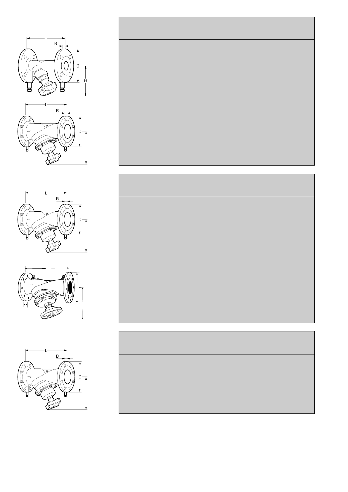
STAF-SG PN25 **)
Ductile iron/Sphäroguß/
Fonte nodulaire
TA.No DN *) L H D B Kvs
TA.Nr
No.TA
Threaded bonnet/Oberteil eingeschraubt/Tête vissée
Digital handwheel/Digitalhandrad/Poignée digitale
52 182 -020 20 4 150 100 105 16 5.7
-025 25 4 160 109 115 16 8.7
-032 32 4 180 111 140 18 14.2
-040 40 4 200 122 150 19 19.2
-050 50 4 230 122 165 19 33
**) DN 20-50 also fit PN16 flanges.
DN 20-50 auch passend für Gegenflansche PN16.
Les DN 20-50 acceptent également la contre-bride PN 16.
Bolted bonnet/Oberteil geflanscht/Tête boulonnée
Digital handwheel/Digitalhandrad/Poignée digitale
52 182 -065 65-2 8 290 205 185 19 85
-080 80 8 310 220 200 19 120
-090 100 8 350 240 235 19 190
-091 125 8 400 275 270 19 300
-092 150 8 480 285 300 20 420
STAF PN16
Cast iron/Grauguß/Fonte
L
B
STAF-R PN16
Bronze/Rotguß/Bronze
TA.No DN *) L H D B Kvs
TA.Nr
No.TA
Bolted bonnet/Oberteil geflanscht/Tête boulonnée
Digital handwheel/Digitalhandrad/Poignée digitale
52 181 -065 65-2 4 290 205 185 20 85
-080 80 8 310 220 200 22 120
-090 100 8 350 240 220 22 190
-091 125 8 400 275 250 24 300
-092 150 8 480 285 285 24 420
Aluminium handwheel/Aluminiumhandrad/Poignée en aluminium
Measurement point in body/Meßanschluß am Gehäuse/Prises de pression sur le corps
52 180 -093 200 12 600 450 340 30 765
-094 250 12 730 470 405 32 1185
D
H
-095 300 12 850 520 460 32 1450
TA.No DN *) L H D B Kvs
TA.Nr
No.TA
Bolted bonnet/Oberteil geflanscht/Tête boulonnée
Digital handwheel/Digitalhandrad/Poignée digitale
52 181 -765 65-2 4 290 205 185 17 85
-780 80 8 310 220 200 19 120
-790 100 8 350 240 220 21 190
-791 125 8 400 275 250 22 300
-792 150 8 480 285 285 22 420
*) Number of bolt holes/Anzahl der Schraubenlöcher/Nombre de trous par bride
**) DN 20-50 also fit PN16 flanges.
DN 20-50 auch passend für Gegenflansche PN16.
Les DN 20-50 acceptent également la contre-bride PN 16.
3
Kvs = m
Kvs = m
Kvs = m
/h at a pressure drop of 1 bar and fully open valve.
3
/h bei einem Druckverlust von 1 bar und vollgeöffnetem Ventil.
3
/h pour une perte de charge de 1 bar, la vanne complètement ouverte.
2

Example DN 65
Beispiel DN 65
Exemple DN 65
Fig. 1/Bild 1 Valve closed/Ventil geschlossen/Vanne fermée Fig.2/Bild 2 The valve is preset 2.3/Gewünschte Voreinstellung 2.3/
Presetting
It is possible to read the preset value on
the handwheel. The number of turns
between the fully open and closed
positions is
4 turns for DN 20-50, (digital)
8 turns for DN 65-150,
12 turns for DN 200-250 and
16 turns for DN 300.
Initial setting of a valve for a particular
pressure drop, e g corresponding to 2.3
turns on the graph, is carried out as
follows:
1. Close the valve fully (Fig 1)
2. Open the valve to the preset value
2.3 turns (Fig. 2).
3.
DN 20-50, DN 200-300:
Remove the handwheel screw
without changing the setting, by
means of an Allen key *)
DN 65-150:
handwheel screw, but insert the Allen
key through the hole in it.
4. Turn the inner stem clockwise until
the stop is reached with the same
Allen key (long end), and refit the
handwheel screw.
5. The valve is now preset.
To check the presetting of a valve, open
it to the stop position; the indicator then
shows the presetting number, in this
case 2.3 (Fig. 2).
As a guide to determining the correct
valve size and setting (pressure drop)
there are graphs for each size of valve
showing the pressure drop at different
settings and water volumes.
Sealing
DN 20-50 can be locked similarly to
STAD.
Do not remove the
Voreinstellung
Der Voreinstellwert ist auf einer Digitalanzeige oder Noniusskala ablesbar.
Anzahl der Handradumdrehungen
zwischen völlig geschlossen und
geöffnet:
4 Umdrehungen bei DN 20-50 (digital)
8 Umdrehungen bei DN 65-150
(digital)
12 Umdrehungen bei DN 200-250
16 Umdrehungen bei DN 300
Um einen Druckabfall entsprechend der
Ziffer 2.3 des Diagrammes zu erreichen,
muß die Einstellung des Ventiles wie
folgt vorgenommen werden:
1. Das Ventil ganz schließen
(siehe Bild 1)
2. Ventil bis zur gewünschten Ein-
stellung 2.3 öffnen (siehe Bild 2).
3.
DN 20-50, DN 200-300:
Befestigungsschraube des Handrades mit Innensechskantschlüssel
lösen*). Handradschraube entfernen.
DN 65-150:
wird nicht gelöst. Den Innensechskantschlüssel durch die Bohrung der
Handradschraube einführen.
4. Die innere Spindel mit dem langen
Ende des Schlüssels im Uhrzeigersinn bis zum Anschlag eindrehen.
5. Das Ventil ist jetzt voreingestellt.
Handradschraube wieder befestigen:
Das Ventil kann jetzt geschlossen,
jedoch nicht mehr über die gewählte
Voreinstellung hinaus geöffnet werden.
Um die Voreinstellung eines Ventiles zu
kontrollieren: Das Ventil ganz öffnen.
Die Anzeige am Handrad zeigt dann
den Voreinstellwert, in diesem Fall die
Ziffer 2.3 an (siehe Bild 2).
Als Anleitung für die Bestimmung einer
richtigen Ventildimension und Voreinstellung (Druckabfall) gibt es Diagramme. Diese Diagramme zeigen den
jeweiligen Druckabfall bei verschiedenen Einstellungen und Wassermengen an.
Plombierung: DN 20-50 kann genau
wie STAD plombiert werden.
Die Handradschraube
Vanne réglée à la position 2.3
Préréglage
Les vannes de DN 20-150 sont munies
d'une poignée numérique à lecture
directe, réglage sur 4 ou 8 tours. La
position de réglage des autres vannes
est lisible sur une échelle Vernier, le
nombre de tours complets étant indiqué
sur une échelle fixe et les fractions de
tour sur l'échelle gravée dans la
poignée, DN 200-250 sur 12 tours et
DN 300 sur 16 tours entre les positions
ouverte et fermée. Supposons qu' après
examen des abaques pression/débit, on
souhaite régler la vanne à la position
2.3. Marche à suivre:
1. Fermer complètement la vanne
(fig .1)
2. La réouvrir à la position de réglage
2.3. (fig.2).
3.
DN 20-50, DN 200-300:
Dévisser la vis de la poignée avec
une clé Allen*) et enlever la vis, sans
changer la position de réglage.
DN 65-150:
du volant. Introduire la clé Allen dans
l'orifice de la vis.
4. Tourner la tige intérieure dans le
sens des aiguilles d'une montre
jusqu'à butée avec la même clé
Allen, puis revisser la poignée
5. La vanne est maintenant préréglée.
Pour vérifier sa position de préréglage,
fermer la vanne. La position de réglage
doit indiquer "0". Ouvrir la vanne jusqu'à
butée. La position de réglage de la
poignée doit, dans cet exemple,
indiquer 2.3 tours (fig. 2).
Pour déterminer la dimension et la
position de préréglage correctes d´une
vanne, se reporter aux abaques fournis
pour chaque diamètre, qui donnent,
pour les différentes positions de
préréglage, la perte de charge en
fonction du débit.
Plombage: Le plombage des vannes
DN 20-50 s'effectue comme pour les
vannes STAD.
Ne pas desserrer la vis
DN *) Allen key
20- 50 3 mm 52 187-103
65-150 5 mm -105
200-300 8 mm —
DN *) Innensechskantschlüssel
20- 50 3 mm 52 187-103
65-150 5 mm -105
200-300 8 mm —
DN *) Clé Allen
20- 50 3 mm 52 187-103
65-150 5 mm -105
200-300 8 mm —
3
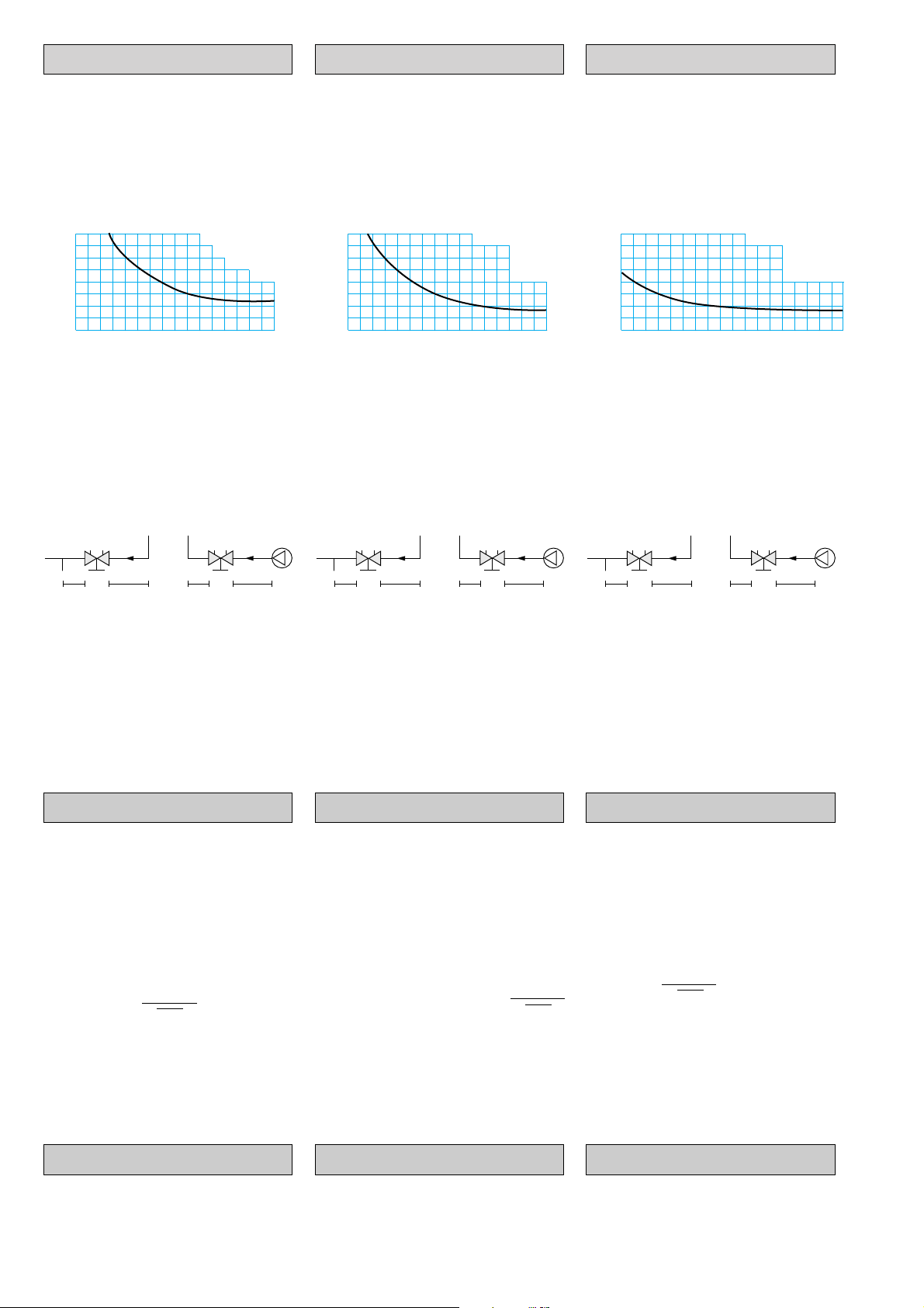
Measuring accuracy
Meßgenauigkeit
Précision
The wheel setting is calibrated and must
not be changed
Flow deviation at different settings
Die Handradpositionen sind kalibriert
und dürfen nicht geändert werden.
Durchflußabweichung bei
verschiedenen Einstellungen
Le réglage de la manette est calibré et
ne doit pas être modifié.
Ecart relatif maxi (en % de la valeur
Kv)
DN 20-50 DN 65-150 DN 200-300
± % 16
14
12
10
8
6
4
2
0
0.5 1,0 1,5 2,0 2,5 3,0 3,5 4,0 *)
The curve above is valid for valves with
normal pipe fittings **).
Try also to avoid mounting other items
and pumps immediately before the
valve.
± % 16
14
12
10
8
6
4
2
0
12345678*)
Obige Kurve hat Gültigkeit für Ventile in
Verbindung mit üblichen Rohranschlüssen.
Pumpen und sonstige Armaturen sollten
vor dem Mengenabgleichventil unter
Einhaltung der unten angeführten
Mindestabstände installiert werden.
± % 16
14
12
10
8
6
4
2
0
234567891011121416*)
La courbe ci-dessous est valable
lorsque la vanne est montée normalement **)sur la tuyauterie et selon les
règles de l'art. Il faut éviter de les
monter immédiatement en aval d'une
pompe par exemple ou d'une autre
robinetterie ou d'un coude. La pression
différentielle limite ne doit pas être
dépassée pour le réglage.
STAF
STAF
STAF
STAF
STAF
STAF
2 D
*) Setting, no. of turns, at specified flow
direction**)
**) The valve can be installed with the
opposite flow direction. The stated flow
information also applies in this direction
although tolerances are larger (max 5%
additional) on settings of 2.5 turns and
above.
10 D2 D5 D
Correction factors
For liquids other than water (20°C) the
values from the CBI/DTM-C can be
adjusted as follows:
Decrease the flow by a factor
depending on the square root of the
specific weight (weight per unit volume)
(γ) in tons/m
Flow read off from the CBI/DTM-C
= Q
CBI/DTM-C
Actual flow =
This correction applies to liquids having
essentially the same viscosity as water
(≤20 cSt = 3°E = 100 S.U.) i.e. most
water/glycol mixtures and water/brine
solutions.
3
.
Q
CBI/DTM-C
√ γ
2 D
*) Einstellung, Anzahl Umdrehungen
bei Durchflußgemäß Gehäusemarkierung**)
**) Das Ventil kann in umgekehrter
Durchflußrichtung angeströmt werden. Die
angegebenen Durchflußmengen gelten auch
für diese Richtung, jedoch treten bei einer
Einstellung von mehr als 2.5 Umdrehungen
größere Abweichungen (zusätzlich 5%) auf.
10 D2 D5 D
Korrekturfaktoren
Für andere Flüssigkeiten als sauberes
Wasser (20°C) können die Angaben
von CBI/DTM-C wie folgt berichtigt
werden: Den Volumenstrom durch die
Quadratwurzel des Volumengewichts
(γ) in t/m
Von CBI/DTM-C angezeigter
Volumenstrom = Q
Tatsächlicher Volumenstrom =
Obiges gilt für Flüssigkeiten mit etwa
gleicher Viskosität (≤20 cSt = 3°E =
100 S.U.) wie Wasser, d.h. für die
meisten Wasser-Glykol-Mischungen
und Salzwasserlösungen.
3
teilen.
CBI/DTM-C
Q
CBI/DTM-C
√ γ
2 D
*) Position de réglage (Nombre de tours)
dans la direction de débit indiquée**)
**) La vanne peut être montée en sens
contraire de la direction de débit indiquée, la
courbe s’appliquant également à cette
direction, les déviations étant cependant plus
importantes (5% au maximum pour un
réglage de 2.5 ou plus.
10 D2 D5 D
Facteurs de correction
Pour d'autres fluides que l'eau (20°C)
les résultats affichés par le CBI/DTM-C
peuvent être corrigés comme suit:
Diviser le débit par la racine carrée du
poids volumique (densité) (γ) en
tonne/m
Si le débit indiqué par le CBI/DTM-C =
Q
Débit réel =
Ceci est valable pour des fluides ayant
une viscosité à peu près identique à
l'eau (≤20 cSt = 3°E = 100 S.U.), c'està-dire la plupart des solutions d'eau à
base de glycol et d'autres antigels.
Dans le cas où la correction de viscosité
est importante, nous consulter.
CBI/DTM-C
3
.
on a:
Q
CBI/DTM-C
√ γ
Formulae
TA can supply a simple computer
program, for use on PCs, for calculation
of presettings.
4
Formeln
Zur Bestimmung der Voreinstellwerte in
hydraulischen Systemen gibt es bei TA
Programme für IBM kompatible PC's.
Formules
Pour la détermination des valeurs de
pré-réglage, TA peut fournir un
programme pour PC compatible -IBM.
 Loading...