

Page 1

Software Version V 2.0 Bestellnummer / Order No. 9103-0489 DE/UK
BETRIEBSANLEITUNG
USER MANUAL
HV-SERIES
PS 3000 HV
Page 2

2
Seite / Page
Deutsch ........................................................................................................ 3
English ......................................................................................................... 17
Anhang / Appendix A:
Anschlussschema ........................................................................................ 30
Wiring diagram ............................................................................................... 30
Anhang / Appendix B:
Technische Daten ......................................................................................... 32
Technical specifications ............................................................................ 32
Page 3

3
Willkommen.
Wir freuen uns, dass Sie sich für ein -Produkt entschieden haben. Mit Ihrem neuen Netzteil PS 3000 HV
haben Sie ein HiFi-Gerät der Spitzenklasse erworben, bei dessen Konzeption und Entwicklung den Wünschen des
audiophilen Musikliebhabers oberste Priorität eingeräumt wurde.
Die innovativen Problemlösungen, die solide, durchdachte Konstruktion und die verwendeten hochwertigen Materialien
werden dazu beitragen, dass dieses Gerät höchsten Anforderungen und Ansprüchen über viele Jahre genügen wird.
Eine genaue Qualitätsprüfung aller Materialien, die sorgfältige Produktion durch hochqualifizierte Fachkräfte und eine
rechnergesteuerte, vollautomatisierte Endkontrolle gewährleisten die hohe Produktqualität und die Einhaltung aller
Spezifikationen.
In unserer Geräteproduktion wird der Einsatz aller umwelt- und gesundheitsgefährdenden Stoffe, wie z. B. chlorhaltige
Lösungsmittel und FCKWs, vermieden. Darüber hinaus verzichten wir wo irgend möglich auf Kunststoffe (insbesondere
auf PVC) als Konstruktionselement. Stattdessen wird auf Metalle oder andere unbedenkliche Materialien zurückgegriffen, die einerseits gut recyclebar sind und andererseits eine sehr gute elektrische Abschirmung ergeben.
Durch unsere massiven Ganzmetallgehäuse wird eine Beeinträchtigung der Wiedergabequalität durch äußere Störquellen ausgeschlossen. Die von den Geräten ausgehende elektromagnetische Strahlung (Elektrosmog) wird gut abgeschirmt und auf ein absolutes Minimum reduziert.
Beim Gehäuse des PS 3000 HV werden ausschließlich hochwertigste amagnetische Metalle höchster Reinheit verwendet.
Dadurch werden Wechselwirkungen mit den Audiosignalen ausgeschlossen und eine unverfälschte Wiedergabe garantiert.
Wir bedanken uns für Ihr Vertrauen und wünschen Ihnen viel Freude und Hörvergnügen mit Ihrem PS 3000 HV.
elektroakustik GmbH & Co KG
Zu Ihrer eigenen Sicherheit sollten Sie bitte unbedingt diese Betriebsanleitung vollständig lesen und
insbesondere die Aufstellungs-, Betriebs- und Sicherheitshinweise genau befolgen. Die
Bedienungsanleitung ist Bestandteil des Gerätes. Geben Sie sie bei einem späteren Weiterverkauf
zur Verhinderung von Fehlbedienungen und zur Vermeidung von Gefahren an den Käufer weiter.
Alle verwendeten Bauteile entsprechen den geltenden deutschen und europäischen Sicherheitsnormen
und –standards. Dieses Produkt entspricht den EU_Richtlinien 2014/35/EU, 2014/30/EU, 2009/125/EU,
2011/65/EU + 2015/863 und der 2012/19/EU.
Page 4

4
Inhaltsverzeichnis
Seite
Betrieb
Allgemeines .................................................................................................................... 5
Front ............................................................................................................................... 6
Betrieb ............................................................................................................................ 7
Anschluss und Inbetriebnahme
Anschlusselemente ....................................................................................................... 10
Aufstellung und Verkabelung ........................................................................................ 11
Sicherheitshinweise ...................................................................................................... 12
Sonstiges
Betriebsstörungen ......................................................................................................... 14
Hinweise zum sparsamen Umgang mit Energie .......................................................... 15
Anhang
Anschluss-Schema ....................................................................................................... 30
Technische Daten ......................................................................................................... 32
In der Anleitung verwendete Symbole
Achtung!
Mit diesem Symbol gekennzeichnete Textstellen enthalten wichtige Hinweise, die für einen problemlosen
und sicheren Betrieb des Gerätes unbedingt beachtet werden müssen.
Dieses Symbol markiert Textpassagen, die Ihnen zusätzliche Hinweise und Hintergrundinformation geben
und das Verständnis erleichtern sollen.
Page 5
5
Einleitung
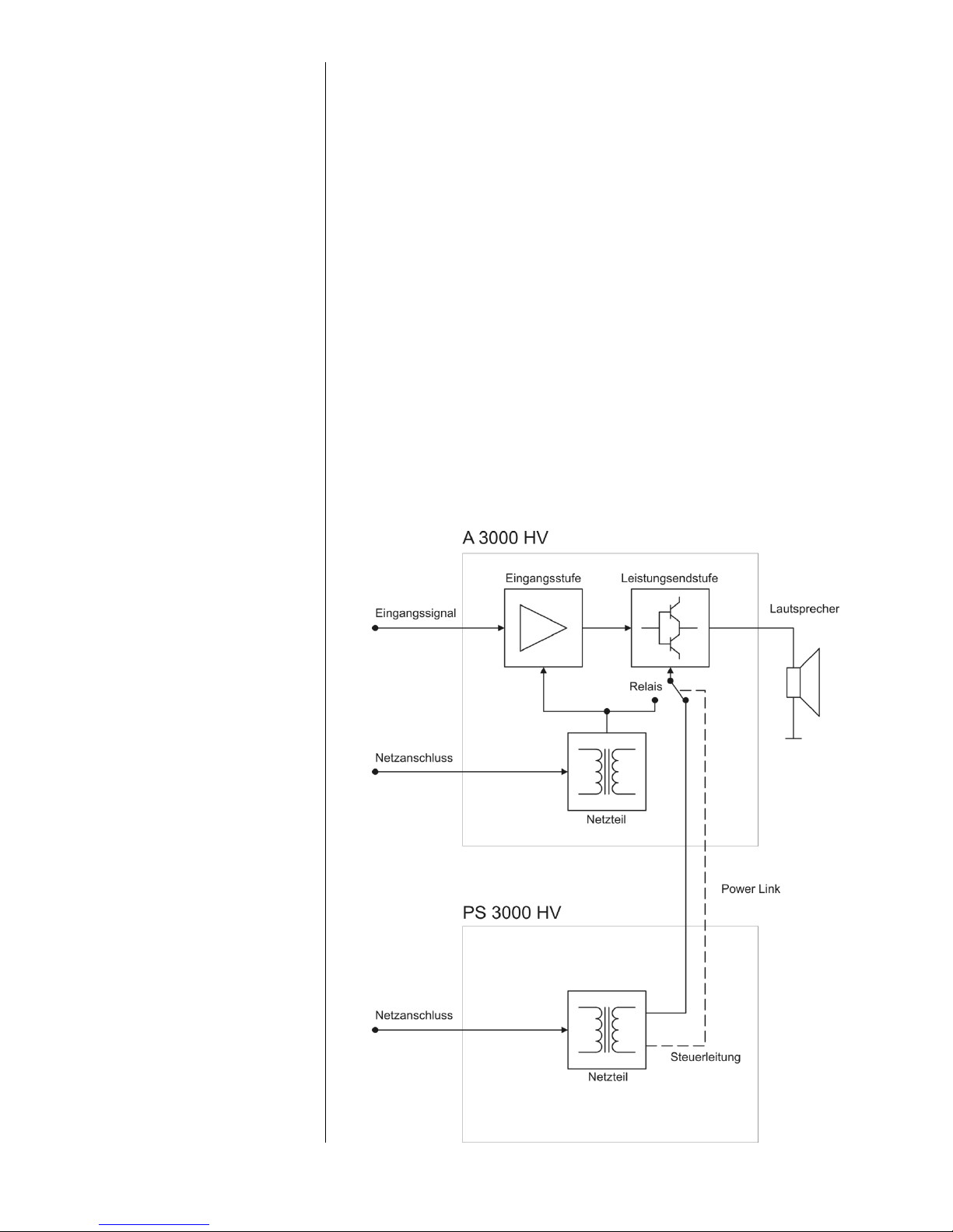
Das PS 3000 HV ist ein zusätzliches Hochleistungsnetzteil und wurde speziell
für die Endstufe A 3000 HV und den Vollverstärker PA 3100 HV entwickelt. Die
Geräte sind mit über 500 Watt Leistung an 4 Ohm auf einem derartig hohen
Klang- und Leistungsniveau, dass eine reine Erhöhung der Ausgangsleistung,
und damit der Spannung, keine signifikanten Klangverbesserungen mehr bringt.
Unsere Forschungs- und Entwicklungsarbeit an Hochleistungsendstufen wie
der M 10 oder S 10 und die daraus entstandene Entwicklung des HVKonzeptes haben ganz eindeutig gezeigt, dass die Stabilität der Spannungsund Stromversorgung durch ein Netzteil von entscheidender und größerer
Bedeutung für die Klangqualität ei-ner Endstufe ist. Wir haben daraus die
richtigen Schlüsse gezogen und eine externe, zusätzliche
Spannungsversorgung entwickelt.
Das Konzept ist genial und funktioniert folgendermaßen: Wenn das
PS 3000 HV über das Spezial-Powerlinkkabel mit M-23-Hochstromkontaktverbindern an die A 3000 HV / den PA 3100 HV angeschlossen wird,
übernimmt das interne Netzteil der Verstärker die Versorgung der
Eingangsstufen und der Hochspannungs-verstärker. Dort wird wesentlich
weniger Leistung umgesetzt und zwangsläufig entstehen auch wesentlich
weniger Störungen im A 3000 HV / PA 3100 HV selbst. Das externe PS 3000
HV liefert dann die Versorgung für die Ausgangsstufen des A 3000 HV / PA
3100 HV und damit die großen Ströme für die Leistungsendstufen. Das PS
3000 HV ist mit 1200 VA nochmals deutlich stärker als das Netzteil des
A 3000 HV / PA 3100 HV und verfügt zudem über doppelt so hohe
Siebkapazitäten. Damit werden die Stromlieferfähigkeit und Stabilität des
Gesamtsystems signifikant verbessert.
Der große klangliche Vorteil dieses Konzeptes besteht darin, dass die Ladeströme und netzinduzierte Störungen aus den Verstärkern ferngehalten werden,
denn diese können negativen Einfluss auf die Klangqualität haben.
Funktionsweise
Page 6
6
Front
Netzmonitor (MAINS MONITOR)
Allgemeines
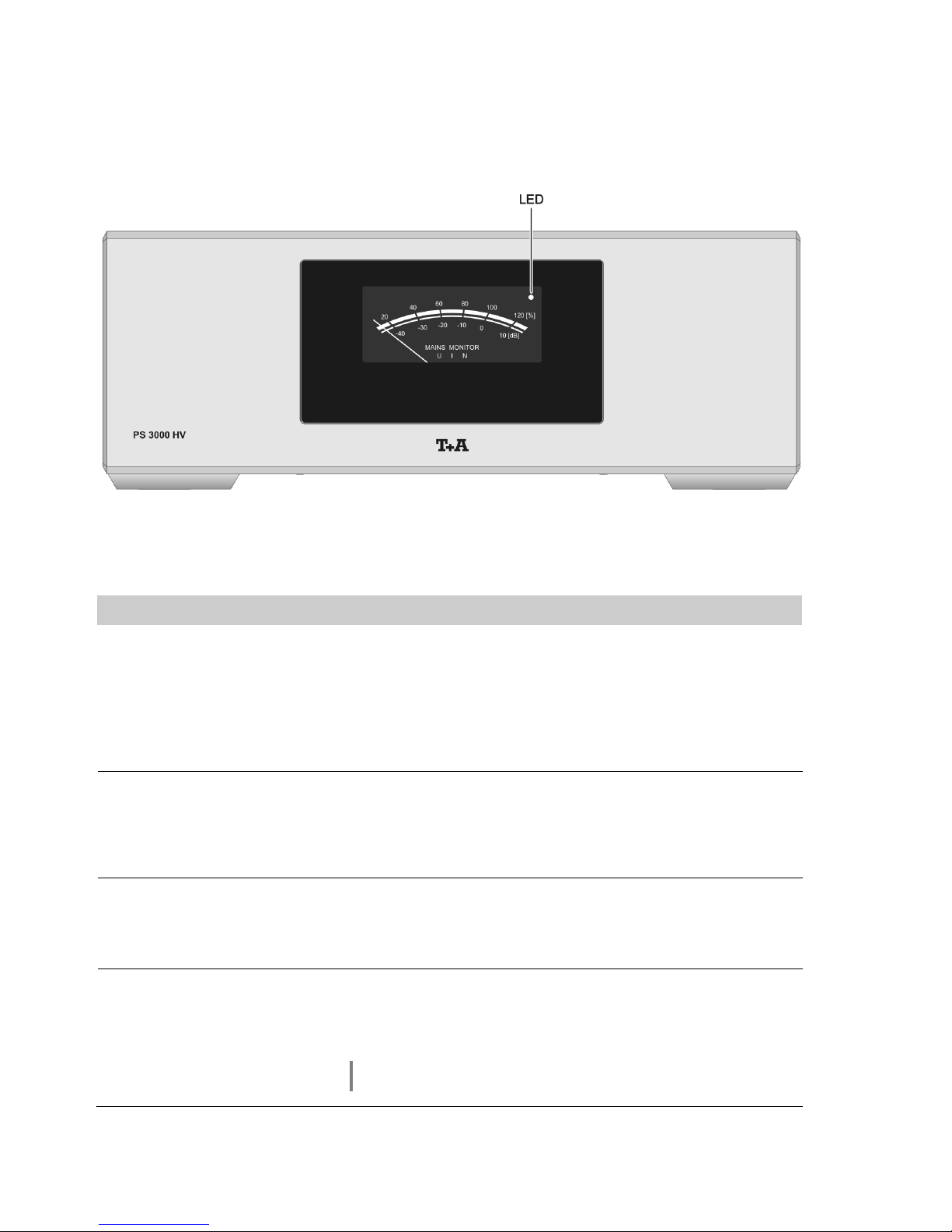
Das PS 3000 HV verfügt über einen Netzmonitor zur Beurteilung der
Stabilität und Qualität des Versorgungsnetzes. Der Netzmonitor zeigt
wahlweise die Betriebsspannung, die Stromaufnahme oder den Störpegel
auf der Netzleitung an.
Der aktuell eingestellte Anzeigemodus wird durch die Leuchtdiode (LED)
angezeigt. Die Umschaltung der Anzeige erfolgt entweder über den
angeschlossenen A 3000 HV, einen P 3000 HV oder einen
angeschlossenen PA 3100 HV (siehe Kapitel 'Betrieb').
U (LED aus)
In der Anzeigeart U zeigt der Netzmonitor die Betriebsspannung an. Je
nach Belastung und Netzspannung kann diese variieren. Ein Anzeigewert
von 100% entspricht der nominalen Netzspannung (115V oder 230V je
nach Ausführung). Für optimalen Betrieb sollte die Anzeige zwischen 90%
und 110% liegen.
I (LED leuchtet rot)
In der Anzeigeart I zeigt der Netzmonitor die Stromaufnahme des
PS 3000 HV an. 100% entspricht der maximalen Leistung des PS 3000 HV.
Die Anzeige sollte nicht dauerhaft über 100% liegen. Kurze Stromspitzen
über 100% sind für das PS 3000 HV nicht kritisch.
N (LED leuchtet grün)
In der Anzeigeart N zeigt der Netzmonitor die Störungen auf dem
Versorgungsnetz an. Das heißt, je mehr Störungen auf der Netzspannung
sind, desto höher der Anzeigewert. Bei Werten über -35dB empfehlen wir
ein qualitativ hochwertiges Netzfilter wie z.B. die Power Bar.
Gegebenenfalls sollte die Netzinstallation überprüft und Störquellen
beseitigt werden.
Page 7

7
Betrieb
Einschalten
Das Netzteil PS 3000 HV wird durch den angeschlossenen PA 3100 HV /
A 3000 HV automatisch mit ein- und ausgeschaltet.
Um das PS 3000 HV vollständig von der Netzspannung zu trennen, ist es
erforderlich den Netzstecker zu ziehen!
Das Gerät verfügt über eine Softstartautomatik, welche dafür sorgt, dass die
Siebkondensatoren sanft aufgeladen werden. Durch das sanfte Starten des
Gerätes wird außerdem verhindert, dass die Haushaltssicherungen durch
schlagartiges Einschalten ausgelöst werden.
Durch die Softstartfunktion dauert es eine gewisse Zeit, bis das Netzteil seine
Startroutine absolviert hat. Während dieser Zeit, leuchtet die Leuchtdiode des
Netzmonitors orange. Sobald sich alle Spannungen eingestellt haben und das
Gerät betriebsbereit ist, erlischt die Leuchtdiode, bzw. ändert sich die Farbe
(und entsprechend der Anzeigemodus des Netzmonitors) in den Zustand, den
sie vor dem letzten Ausschalten hatte.
Während des Einschaltvorgangs leuchtet die Leuchtdiode im Normalfall
dauerhaft orange. Da die Startroutine die erforderlichen Parameter
abschnittsweise prüft, kann es durchaus vorkommen, dass die Leuchtdiode
kurzzeitig blinkt. In dem Fall wartet das PS 3000 HV darauf, dass bestimmte
Betriebsparameter ihre Sollwerte erreichen. Das Blinken signalisiert lediglich
eine kurze Verzögerung des Einschaltvorgangs.
Sollte die Leuchtdiode dauerhaft orange blinken, so warten Sie bitte
mindestens 3 Minuten. Es kann sein, dass die Spannungen des PS 3000 HV
und des A 3000 HV / PA 3100 HV noch nicht zueinander passen und das
PS 3000 HV seinen Einschaltvorgang deshalb noch nicht beenden kann.
Sollte die Leuchtdiode während der Startroutine rot blinken, hat die
Softstartautomatik einen Fehler erkannt. In diesem Fall lässt sich das
PS 3000 HV erst nach ziehen des Netzsteckers (min. 10 Sekunden) erneut
einschalten. Sollte die Leuchtdiode beim erneuten Einschalten wieder rot
blinken, ziehen Sie bitte den Netzstecker des PS 3000 HV und kontaktieren
eine autorisierte Fachwerkstatt.
Page 8

8
Anzeige umschalten
Der Anzeigemodus des Netzmonitors lässt sich über einen angeschlossenen
Endverstärker A 3000 HV, über den Vorverstärker P 3000 HV oder den
Vollverstärker PA 3100 HV umschalten.
Umschalten des Anzeigemodus über den P 3000 HV / PA 3100 HV:
Das Umschalten der Messart über den P 3000 HV erfolgt im Konfigurations -
Menü des P 3000 HV. Detaillierte Informationen zur Bedienung entnehmen Sie
bitte der Bedienungsanleitung des P 3000 HV (Siehe Kapitel
'Grundeinstellungen des P 3000 HV').
Sollten Sie zwei PS 3000 HV betreiben (Monobetrieb), werden beide
PS 3000 HV synchron verstellt.
Umschalten des Anzeigemodus über den A 3000 HV:
Durch einen langen Druck auf die Taste des A 3000 HV wird der
Anzeigemodus auf die nächste Betriebsart weitergeschaltet.
Bei Betrieb von zwei A 3000 HV mit zwei PS 3000 HV wird nur die Betriebsart
des direkt an den A 3000 HV angeschlossenen PS 3000 HV umgeschaltet.
Dadurch ist es möglich an beiden PS 3000 HV unterschiedliche Einstellungen
vorzunehmen, um z.B. Spannung und Störung gleichzeitig überprüfen zu
können.
Page 9

9
Installation
Inbetriebnahme
Sicherheitshinweise
In diesem Kapitel werden alle Dinge von grundsätzlicher Bedeutung für die Aufstellung und Inbetriebnahme beschrieben,
die nicht für den täglichen Umgang mit dem Gerät relevant sind, die aber trotzdem vor dem ersten Gebrauch gelesen
und beachtet werden sollten.
Page 10
10
Anschlusselemente
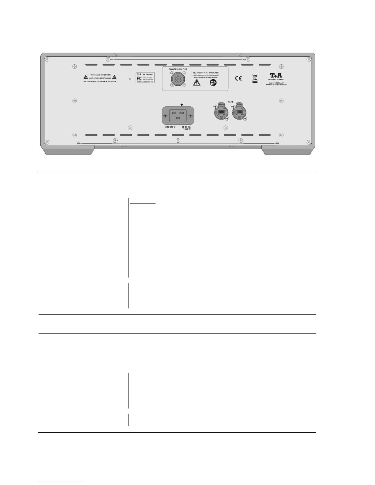
POWER LINK OUT
Anschlussbuchse zum Anschluss an einen A 3000 HV
Achtung!
An diese Buchse darf ausschließlich ein Endverstärker A 3000 HV
oder ein Vollverstärker PA 3100 HV angeschlossen werden. Der Anschluss
anderer Geräte ist nicht gestattet!
Über die Power Link Verbindung können sehr hohe Ströme fließen und es liegen
hohe Spannungen an. Zur Verbindung der beiden Geräte ist daher nur das von
mitgelieferte Power Link Kabel zugelassen.
Das Gerät besitzt eine Sicherheitsabschaltung, welche bei Entfernen des Power
Link Kabels verhindert, dass die Kontakte Spannung führen. Zu Ihrer Sicherheit
und um Korrosion der Kontakte zu vermeiden sollten diese trotzdem nicht berührt
werden. Entfernen Sie den Schraubverschluss oder das Power Link Kabel nur,
wenn alle Geräte vom Netz getrennt sind.
Das mitgelieferte Power Link Kabel ist auf eine Aufstellung der Geräte
übereinander abgestimmt. Für andere Aufstellungssituationen, wie z.B. die
Aufstellung nebeneinander, ist im Zubehör ein längeres Kabel erhältlich
(Art.Nr.: 4084-99401).
H LINK
Steuereingang zum Anschluss an -Geräte mit H LINK – Ausgang.
Netzeingang
Diese Buchse dient dem Netzanschluss.
Zum korrekten Netzanschluss beachten Sie bitte die Hinweise in den Kapiteln
'Aufstellung und Verkabelung' und 'Sicherheitshinweise'.
Achtung!
Das PS 3000 HV muss an die gleiche Netzphase wie der verbundene A 3000 HV
/ PA 3100 HV angeschlossen sein.
Das PS 3000 HV darf unter keinen Umständen an Powerconditioner oder
ähnliche Geräte angeschlossen werden, die in Reihe vorgeschaltet werden.
Soll das Gerät längere Zeit nicht benutzt werden, ist es vorteilhaft, das Gerät vom
Netz zu trennen. Dazu muss der Netzstecker gezogen werden.
Page 11
11
Aufstellung und Verkabelung
Packen Sie das Gerät vorsichtig aus und heben Sie die Originalverpackung
sorgfältig auf. Der Karton und das Verpackungsmaterial sind speziell für dieses
Gerät konzipiert und bei späteren Transporten ein sicherer Behälter.
Transportieren oder versenden Sie Gerät ausschließlich in der originalen
Verpackung um Gerätedefekte zu vermeiden.
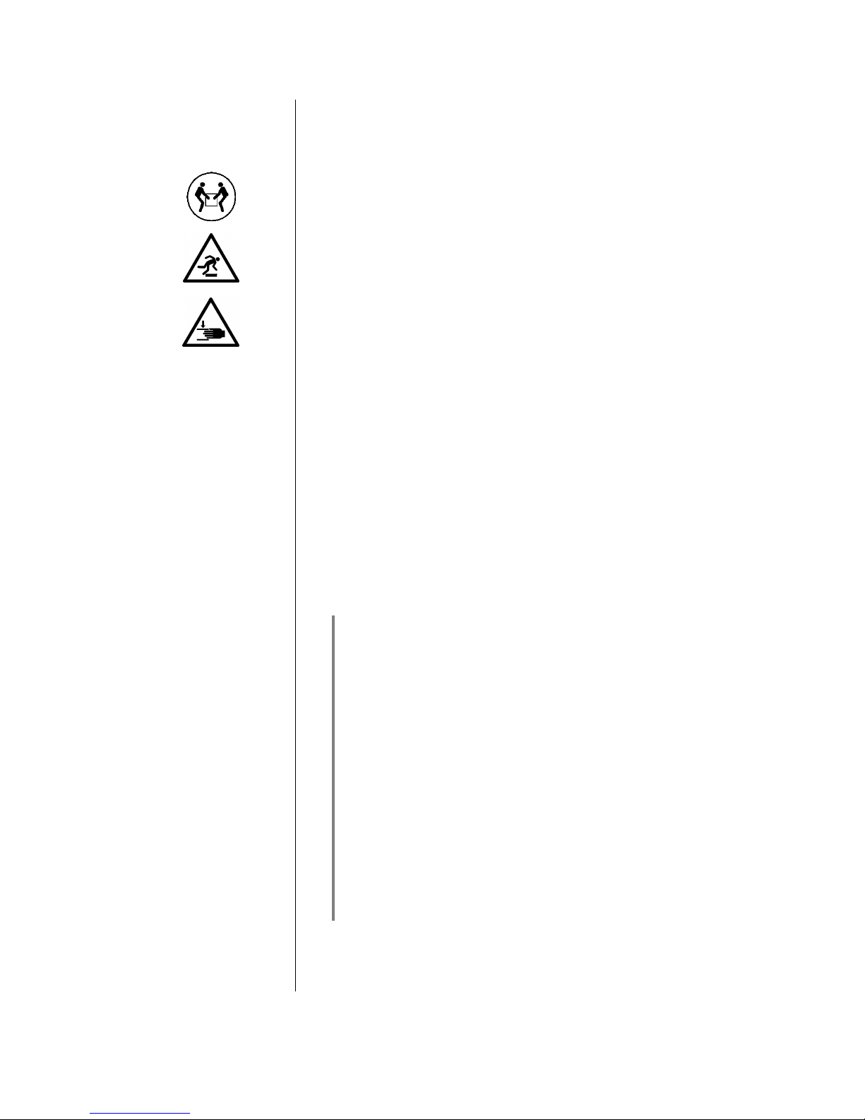
Das Gerät hat ein sehr hohes Gewicht - Vorsicht beim Auspacken und beim
Transport. Heben und transportieren Sie das Gerät immer mit 2 Personen.
Aufgrund der gesetzlich bestehenden Vorschriften zum Heben schwerer Lasten
darf der Transport des Gerätes nicht von Frauen vorgenommen werden.
Achten Sie auf sicheren und festen Griff, lassen Sie das Gerät nicht fallen,
tragen Sie beim Bewegen des Gerätes Sicherheitsschuhe.
Stolpern Sie nicht. Achten Sie auf eine freie Bewegungsfläche, entfernen Sie
Hindernisse und Stolperstellen auf dem Transportweg. Vorsicht beim Abstellen!
Um Quetschungen zu vermeiden achten Sie darauf, dass Ihre Finger nicht
zwischen Gerät und Aufstellfläche gelangen.
War das Gerät größerer Kälte ausgesetzt (z. B. beim Transport), so ist mit der
Inbetriebnahme zu warten, bis sich das Gerät auf Raumtemperatur aufgewärmt
hat und das Kondenswasser restlos verdunstet ist.
War das Gerät eingelagert oder längere Zeit nicht in Betrieb (> 2 Jahre) so
sollte unbedingt vor Wiederinbetriebnahme eine Kontrolle in einer
Fachwerkstatt durchgeführt werden.
Vor der Aufstellung des Gerätes auf empfindlichen Lack- oder Holzoberflächen
sollte an einer nicht sichtbaren Stelle die Verträglichkeit mit den Gerätefüßen
überprüft werden und ggf. eine geeignete Unterlage verwendet werden. Wir
empfehlen eine Standfläche aus Stein, Glas, Metall o.Ä.
Das Gerät ist waagerecht auf einer festen stabilen, ebenen Unterlage
aufzustellen (siehe Kapitel „Sicherheitshinweise“). Bei Aufstellung auf
Resonanzdämpfern oder Entkopplungsgliedern ist darauf zu achten, dass die
Standsicherheit des Gerätes nicht beeinträchtigt wird.
Die Aufstellung darf nur an einem gut belüfteten, trockenen Ort erfolgen, wobei
direkte Sonneneinstrahlung und die Nähe von Heizkörpern zu vermeiden sind.
Das Gerät darf nicht in der Nähe von wärmeproduzierenden, wärmeempfindlichen oder leicht brennbaren Gegenständen bzw. Geräten aufgestellt werden.
Hinweise zum Anschluss:
Schrauben Sie die Power Link Stecker immer vollständig fest. Achten Sie
darauf, dass der Stecker nicht verkantet aufgeschraubt wird. Beachten Sie die
Markierung der Buchse und des Steckers (siehe Anschlussbild im Anhang A).
Schalten Sie das PS 3000 HV nur mit vollständig festgeschraubtem Power
Link Kabel ein.
Die H LINK-Buchse verbinden Sie mit der H LINK-Buchse des Endverstärkers
(siehe Anschlussbild im Anhang A).
Das Gerät ist für den Betrieb an einer Schutzleitersteckdose vorgesehen.
Schließen Sie es bitte mit dem beiliegendem Netzkabel an eine entsprechende, vorschriftsmäßig geerdete Steckdose an. Zur Erreichung des
maximalen Störabstandes muss der Netzstecker so in die Netzsteckdose
gesteckt werden, dass die Phase an dem Kontakt der Netzeingangsbuchse
angeschlossen wird, der mit einem Punkt () gekennzeichnet ist. Verwenden
Sie keine Netzschalter wie z.B. schaltbare Mehrfachsteckdosen.
Kurzes ein- und ausschalten der Netzspannung kann dazu führen, dass die
Netzsicherung auslöst.
Achten Sie darauf, dass die benutze Steckdose für den Betrieb mit der
geforderten Leistung ausgelegt ist. (PS 3000 HV und A 3000 HV /
PA 3100 HV benötigen zusammen maximal 3300 Watt)
Nachdem die Anlage vollständig verkabelt ist, schalten Sie diese ein. Falls bei
der Inbetriebnahme des Gerätes Probleme auftreten sollten, haben diese
oftmals einfache Ursachen, die leicht zu beheben sind. Lesen Sie dazu das
Kapitel 'Betriebsstörungen' dieser Betriebsanleitung.
Page 12

12
Sicherheitshinweise
Zu Ihrer eigenen Sicherheit sollten Sie bitte unbedingt diese Betriebsanleitung
vollständig lesen und insbesondere die Aufstellungs-, Betriebs- und Sicherheitshinweise genau befolgen.
Aufstellung
Beachten Sie das Gewicht des Gerätes. Stellen Sie das Gerät niemals auf
einen instabilen Platz. Das Gerät kann herunterfallen und dabei ernsthafte
Verletzungen oder Todesfälle verursachen. Viele Verletzungen, vor allem bei
Kindern können bei Beachtung folgender einfacher Vorsichtsmaßnahmen
vermieden werden:
Benutzen Sie nur Möbel, welche das Gerät sicher tragen können.
Stellen Sie sicher, dass das Gerät nicht über die Ränder des tragenden
Möbelstücks hinausragt.
Platzieren Sie das Gerät nicht auf hohen Möbeln (z.B. Bücherregale) ohne
beides, Möbel und Gerät, sicher zu verankern.
Klären Sie Kinder über die Gefahren auf, die beim Klettern auf Möbel zum
Erreichen des Gerätes oder seiner Bedienelemente entstehen.
Sorgen Sie beim Einbau in Regale oder Schränke unbedingt für ausreichende
Luftzufuhr und sorgen Sie dafür, dass die Wärme des Gerätes abgeführt
werden kann. Ein Wärmestau beeinträchtigt die Lebensdauer des Gerätes und
ist eine Gefahrenquelle. Um das Gerät herum muss ein Freiraum von 10 cm zur
Wärmeabfuhr bleiben.
Es dürfen keine wärmeisolierenden Gegenstände (z. B. Decken oder andere
Geräte mit ebener Bodenplatte ohne Standfüße) direkt auf das
Verstärkergehäuse gestellt werden.
Das Gerät ist so aufzustellen, dass eine Berührung sämtlicher Geräteanschlüsse (insbesondere durch Kinder) ausgeschlossen ist. Die Hinweise und
Angaben im Kapitel 'Aufstellung und Verkabelung' sind unbedingt zu
beachten.
Anschluss
Die mit dem -Symbol gekennzeichneten Anschlussklemmen können hohe
Spannungen führen. Ein Berühren der Anschlussstellen oder der Leiter der
daran angeschlossenen Kabel ist zu vermeiden. An diese Anschlussstellen
angeschlossene Leitungen erfordern das Verlegen durch eine unterwiesene
Person oder die Verwendung von anschlussfertigen Leitungen.
Stromversorgung
Das Gerät ist für den Betrieb an einer Schutzleitersteckdose vorgesehen.
Schließen Sie es bitte mit dem beiliegendem Netzkabel an eine entsprechende,
vorschriftsmäßig geerdete Steckdose an.
Die für das Gerät erforderliche Stromversorgung ist dem Aufdruck an der Netzgerätebuchse zu entnehmen. An andere Stromversorgungen darf das Gerät
nicht angeschlossen werden. Bei längerer Nichtbenutzung sollte der Netzstecker des Gerätes aus der Steckdose gezogen werden.
Netzkabel / Netzstecker
Netzkabel müssen so verlegt werden, dass keine Gefahr der Beschädigung
(z. B. durch Trittbelastung oder durch Möbelstücke) besteht. Besondere Vorsicht ist dabei an den Steckern, Verteilern und an den Anschlussstellen des
Gerätes geboten. Auf den Netzstecker darf keine übermäßige Krafteinwirkung
ausgeübt werden.
Abziehen des Netzsteckers trennt das Gerät bei Wartung oder Servicearbeiten
vom Netz. Bitte achten Sie darauf, dass der Stecker ohne Schwierigkeiten zugänglich und benutzbar ist.
Geräteöffnungen
Durch die Geräteöffnungen dürfen keine Flüssigkeiten oder Fremdkörper in das
Gerät gelangen. Im Inneren führt das Gerät Netzspannung, es besteht die
Gefahr eines tödlichen elektrischen Schlages.
Schützen Sie das Gerät vor Tropf- und Spritzwasser und stellen Sie keine
Blumenvasen oder andere Gefäße mit Flüssigkeiten auf das Gerät.
Stellen Sie keine offenen Flammen, wie z. B. Kerzen auf das Gerät.
Aufsichtspflicht
Wie alle Elektrogeräte so sollte auch dieses Gerät nicht unbeaufsichtigt betrieben
werden. Es ist darauf zu achten, dass es für kleine Kinder unerreichbar ist.
Reparatur und
Beschädigung
Das Gerät darf nur vom qualifizierten Fachmann geöffnet werden. Reparaturen
und das Auswechseln von Sicherungen sind von einer autorisierten
Fachwerkstatt durchzuführen. Außer den in der Betriebsanleitung beschriebenen Handgriffen dürfen vom Benutzer keinerlei Arbeiten am Gerät
vorgenommen werden.
Page 13

13
Bei Beschädigungen oder bei Verdacht auf eine nicht ordnungsgemäße
Funktion des Gerätes sollte sofort der Netzstecker gezogen und das Gerät zur
Überprüfung in eine autorisierte Fachwerkstatt gegeben werden.
Überspannung
Überspannungen im Stromversorgungsnetz, dem Kabelnetz oder auf
Antennenanlagen, wie sie z. B. bei Gewittern (Blitzschlag) oder statischen
Entladungen auftreten können, stellen eine Gefährdung für das Gerät dar.
Spezielle Vorschaltgeräte wie Überspannungsprotektoren oder die 'Power
Bar' Netzanschlussleiste bieten einen gewissen Schutz vor Gerätebeschädigungen aus o. g. Gründen.
Eine absolute Sicherheit vor Beschädigung durch Überspannungen kann aber
nur eine vollständige Trennung des Gerätes vom Netz und den Antennenanlagen gewährleisten.
Ziehen Sie zur Trennung sämtliche Netz- und Antennenstecker Ihrer HiFi
Anlage bei Überspannungsgefahr (z. B. bei heraufziehenden Gewittern) aus
den Steckdosen.
Sämtliche Netzversorgungs- und Antennenanlagen, an die das Gerät angeschlossen wird, müssen den geltenden Bestimmungen entsprechen und fachgerecht von einem zugelassenen Installationsbetrieb ausgeführt sein.
Bestimmungsgemäßer
Gebrauch
Das Gerät ist ausgelegt für den Betrieb in gemäßigtem Klima. Zulässiger
Betriebstemperaturbereich +10 … +35. C
Das Gerät ist ausschließlich zur Ton- und/oder Bildwiedergabe im Heimbereich
in trockenen Räumen unter Berücksichtigung aller in dieser Anleitung gemachten Angaben bestimmt.
Bei allen anderen Einsatzzwecken, insbesondere in medizinischen oder sicherheitsrelevanten Bereichen, ist vorher die Zulassung und Eignung des Gerätes
für diesen Einsatz mit dem Hersteller abzuklären und schriftlich genehmigen zu
lassen.
Gerätezulassung und
Konformität mit EGRichtlinien
Das Gerät entspricht im Originalzustand allen derzeit gültigen deutschen und
europäischen Vorschriften. Es ist zum bestimmungsgemäßen Gebrauch in der
EG zugelassen.
Durch das am Gerät befindliche Zeichen erklärt die Konformität mit den
EG-Richtlinien (siehe Seite 3) und den daraus abgeleiteten nationalen
Gesetzen.
Die unveränderte, unverfälschte Werksseriennummer muss außen am Gerät
vorhanden und gut lesbar sein! Die Seriennummer ist Bestandteil unserer
Konformitätserklärung und damit der Betriebszulassung des Gerätes!
Seriennummern am Gerät und in den original Begleitpapieren (insbesondere den Kontroll- und Garantiezertifikaten) dürfen nicht entfernt oder verändert werden und müssen übereinstimmen.
Bei Verstoß gegen diese Bestimmungen gilt die Konformitätszusage von
als widerrufen und ein Betrieb des Gerätes innerhalb der EG ist untersagt
und aufgrund geltender EG und nationaler Gesetze unter Strafandrohung
verboten.
Durch Umbauten am Gerät oder durch Reparaturen oder sonstige Eingriffe von
nicht von autorisierten Werkstätten oder sonstigen Dritten verliert das
Gerät seine Zulassung und Betriebserlaubnis.
An das Gerät dürfen nur original Zubehörteile oder solche Zusatzgeräte
angeschlossen werden, die ihrerseits zugelassen sind und allen geltenden
gesetzlichen Vorschriften genügen.
Auch mit Zusatzgeräten oder als Teil einer Anlage darf das Gerät nur zu den im
Abschnitt 'Bestimmungsgemäßer Gebrauch' genannten Anwendungen eingesetzt werden.
Entsorgung
Für die spätere Entsorgung dieses Produkts stehen örtliche Sammelstellen für
Elektroschrott zur Verfügung.
Pflege des Gerätes
Vor Reinigungsarbeiten am Gerät ist der Netzstecker zu ziehen.
Die Oberflächen des Gerätes sollten zur Reinigung nur mit einem weichen,
trockenen Tuch abgewischt werden.
Verwenden Sie keine scharfen Reinigungs- oder Lösungsmittel!
Vor der Wiederinbetriebnahme muss sichergestellt sein, dass keine Kurzschlüsse an den Anschlussstellen bestehen und dass alle Anschlüsse
ordnungsgemäß sind.
Lagerung
Lagerung des Gerätes in der Originalverpackung an einem trockenen frostfreien
Ort. Lagertemperatur 0...40 °C.
Page 14

14
Betriebsstörungen
Viele Betriebsstörungen haben eine einfache Ursache, die sich leicht beheben lässt. Im folgenden Abschnitt sind einige
mögliche Störungen sowie Maßnahmen zu deren Behebung aufgeführt. Sollte sich eine aufgetretene Störung durch
diese Hinweise nicht beheben lassen, so ziehen Sie bitte umgehend den Netzstecker und wenden sich an eine
-Fachwerkstatt.
Gerät schaltet nicht ein
Ursache 1:
Netzkabel nicht richtig angeschlossen.
Abhilfe:
Überprüfen und fest einstecken.
Ursache 2:
Durch starke Störungen oder elektrostatische Entladungen ist der Prozessor im
Gerät gestört worden.
Abhilfe:
Trennen Sie das Gerät für mindestens 1 Minute vom Netz.
Ursache 3:
Das PS 3000 HV ist mit einer Netzphasenerkennung ausgestattet, diese
erkennt automatisch, ob das Netzkabel korrekt angeschlossen ist. Bei verpolt
angeschlossenem Netzkabel blinkt die LED dauerhaft grün.
Abhilfe:
Ändern Sie die Polung der Netzphase indem der Netzstecker um 180° verdreht
angeschlossen wird.
Ursache 4:
Durchgebrannte Netzsicherung.
Abhilfe:
Die Netzsicherung durch eine autorisierte Fachwerkstatt ersetzen lassen. Es
dürfen nur Sicherungen verwendet werden, deren Bezeichnung mit dem
Geräteaufdruck übereinstimmt!
Ursache 5:
Das Power Link Kabel ist nicht ordnungsgemäß festgeschraubt.
Abhilfe:
Überprüfen Sie die Power Link Verbindung. die Überwurfringe müssen fest
geschraubt sein.
Ursache 6:
Der angeschlossene A 3000 HV / PA 3100 HV ist defekt und schaltet das
PS 3000 HV nicht ein.
Abhilfe:
Wenden Sie sich bitte an eine -Fachwerkstatt.
Ursache 7:
Die Softstartfunktion des PS 3000 HV hat einen Fehler erkannt, und die
Leuchtdiode blinkt auch nach einer Trennung von der Netzspannung (min. 10
Sekunden) weiterhin rot.
Abhilfe:
Wenden Sie sich bitte an eine -Fachwerkstatt.
Nach Ausschalten der
A 3000 HV schaltet das
PS 3000 HV nicht sofort aus
Ursache:
Das HV – Link Kabel ist nicht korrekt angeschlossen.
Abhilfe:
Überprüfen Sie die HV – Link Verbindung. Stecken Sie die Stecker fest in die
Buchsen.
Die LED blinkt dauerhaft
orange
Ursache:
Damit das PS 3000 HV Einschalten kann, müssen im A 3000 HV / PA 3100 HV
die Kondensatoren entladen sein.
Abhilfe:
Schalten Sie den PA 3100 HV / A 3000 HV aus und warten Sie etwa 5 Minuten
bis die Kondensatoren entladen sind.
Page 15

15
Hinweise zum sparsamen Umgang mit Energie
Allgemeines
Das PS 3000 HV entspricht den neuesten Richtlinien zum sparsamen
Verbrauch von Energie (EuP Richtlinie). Dazu trägt das moderne Netzteildesign maßgeblich bei.
Der interne Mikroprozessor sorgt stets dafür, dass Baugruppen, die momentan
nicht benötigt werden, automatisch abgeschaltet werden. Der Mikroprozessor
selbst arbeitet Im Standbybetrieb mit einer niedrigeren.
Im Standbybetrieb beträgt der Stromverbrauch des PS 3000 HV deshalb
weniger als 0,5 Watt.
Wird das Gerät längere Zeit nicht benutzt, sollte das Gerät vom Netz getrennt
werden. Zur Netztrennung den Netzstecker ziehen.
Page 16

16
Page 17

17
Welcome.
We are delighted that you have decided to purchase a product. Your new power supply PS 3000 HV is a Hi-Fi
unit of the highest quality, designed and developed with a single aim as top priority: to satisfy the requirements of the
audiophile music lover.
This unit is the embodiment of innovative thinking and solid quality, exploiting the finest materials and components
available, and all these factors contribute to a machine which will satisfy you're most stringent demands and your most
searching requirements for a period of many years.
Our production areas are supervised by highly qualified expert staff, and all final production units are checked
comprehensively by a fully automated, computer-controlled system to ensure uniformly high quality. We guarantee that
our products meet our own specifications to the full.
At all stages of production we avoid the use of substances which are environmentally unsound or potentially hazardous
to health, such as chlorine-based cleaning agents and CFCs.
We also aim to avoid the use of plastics in general, and PVC in particular, in the design of our products. Instead we rely
upon metals and other non-hazardous materials; metal components are ideal for recycling, and also provide effective
electrical screening.
Our robust all-metal cases exclude any possibility of external sources of interference affecting the quality of reproduction.
From the opposite point of view our products’ electro-magnetic radiation (electro-smog) is reduced to an absolute
minimum by the outstandingly effective screening provided by the metal case.
The case of the PS 3000 HV is built exclusively from the finest-quality non-magnetic metals of the highest purity. This excludes
the possibility of interaction with the audio signals, and guarantees uncoloured reproduction.
We would like to take this opportunity to thank you for the faith you have shown in our company by purchasing this
product, and wish you many hours of enjoyment and sheer listening pleasure with your PS 3000 HV.
elektroakustik GmbH & Co KG
The operation instructions, the connection guidance and the safety notes are for your own good please read them carefully and observe them at all times. The operating instructions are an integral
part of this device. If you ever transfer the product to a new owner please be sure to pass them on to
the purchaser to guard against incorrect operation and possible hazards.
All the components we use meet the German and European safety norms and standards which are
currently valid. This product complies with the EU directives 2014/35/EU, 2014/30/EU, 2009/125/EU,
2011/65/EU + 2015/863 and 2012/19/EU..
Page 18

18
Contents
Page
Operation
Introduction ................................................................................................................... 19
Front panel .................................................................................................................... 20
The unit in use .............................................................................................................. 21
Using the system for the first time
Back panel connections ................................................................................................ 24
Installation and wiring .................................................................................................... 25
Safety Notes .................................................................................................................. 26
FCC Information to the user .......................................................................................... 27
General
Trouble shooting ........................................................................................................... 28
Notes on energy saving ................................................................................................ 29
Appendix
Wiring diagram ............................................................................................................... 30
Technical specifications ................................................................................................. 32
Symbols used in these instructions
Caution!
Text passages marked with this symbol contain important information which must be observed if the
machine is to operate safely and without problems.
This symbol marks text passages which provide supplementary notes and background information; they
are intended to help the user understand how to get the best out of the machine.
Page 19
19
Introduction
The PS 3000 HV is a supplementary mains unit which was developed specifi cally for the A 3000 HV power amplifier and the PA 3100 HV integrated amp.
Both devices deliver more than 500 Watts of power into 4 Ohms, and at such a
high level of sound quality and performance that simply increasing the output
power - and with it the voltage - produces no significant improvement in sound.
Our research and development work in high-performance amplifiers - including
the M10 and S10 - and the development of the HV design philosophy which
flowed from this work, have shown clearly and unambiguously that the stability
of the voltage and current supplied by a mains unit is of major and even crucial
importance to the sound quality of an power amplifiers. From this we have
drawn the only rational conclusion, and developed a supplementary external
power supply.
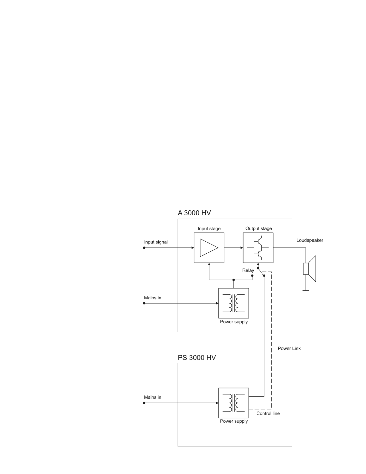
The principle is ingenious, and functions in the following way: if the PS 3000 HV
is connected to the A 3000 HV / PA 3100 HV using the special Power- Link with
M 23 high-current connectors, the internal power supply of the amplifer is used
to supply energy to the input stages and the high-voltage amplifier;
much lower power is required for this part of the system, and as a direct result
the interference generated in the A 3000 HV / PA 3100 HV itself is much lower.
The external PS 3000 HV supplies the energy for the amplifiers output stages,
i.e. it is responsible for the high currents required by the power output stages.
With an output of 1200 VA the PS 3000 HV is substantially more powerful than
the mains unit of the A 3000 HV / PA 3100 HV itself, and can also call upon
twice the reservoir capacity. The net result is a substantial improvement in the
current delivery capacity and stability of the system as a whole.
The great advantage of this arrangement in terms of sound quality is that the
A 3000 HV / PA 3100 HV is effectively isolated from the load currents and
mains-induced interference which can have an adverse effect upon sound
quality. The PS 3000 HV is controlled completely by the connected device via
the HLink bus and the Power - Link connection.
Functional principle
Page 20
20
Front panel
Mains monitor (MAINS MONITOR)
Introduction
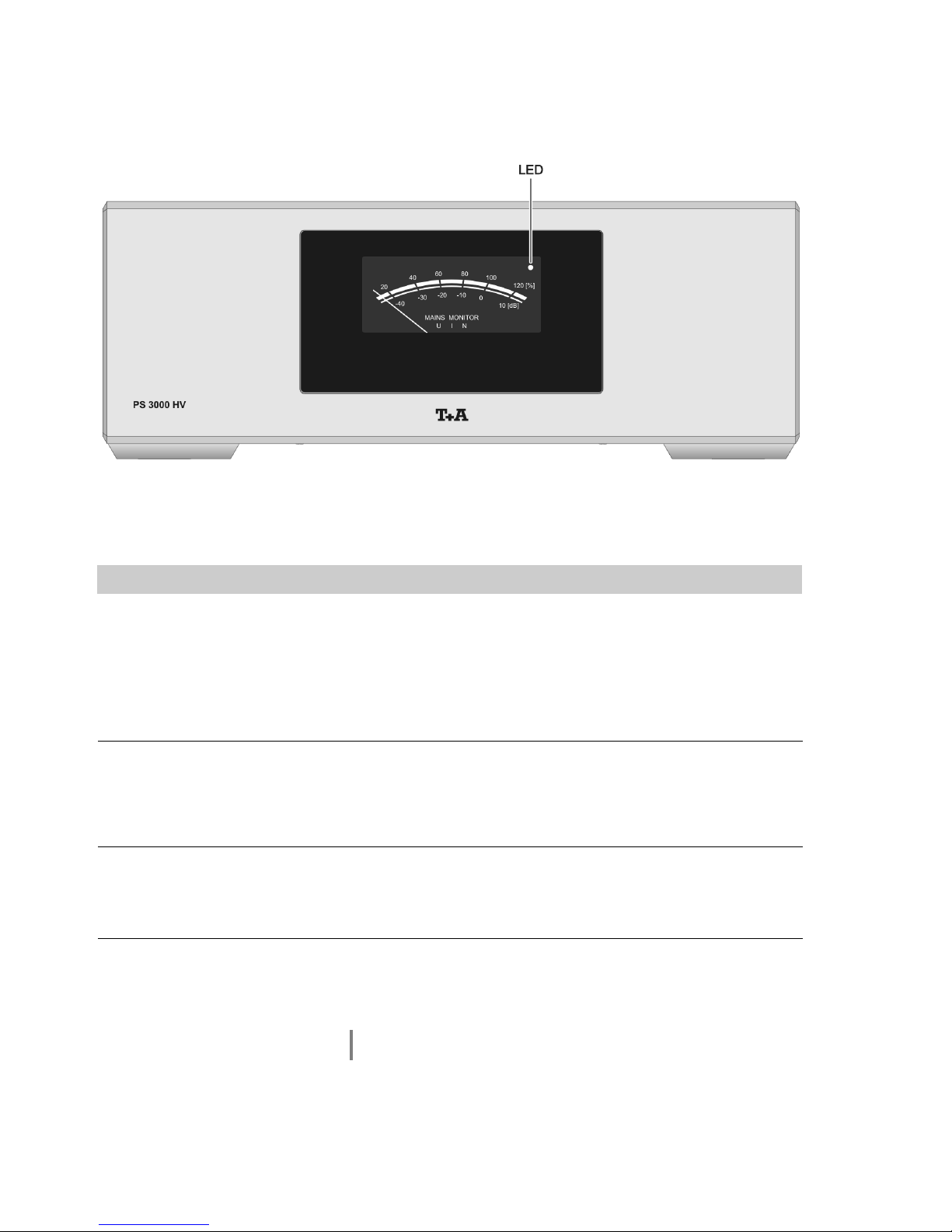
The PS 3000 HV features a mains monitor which assesses the stability and
quality of the mains power supply. The mains monitor can be set to display
the operating voltage, the current drain or the level of interference in the
mains cable.
The display mode currently set is indicated by the light-emitting diode
(LED). The display can be changed via the A 3000 HV, the P 3000 HV
connected to the A 3000 HV or via a connected PA 3100 HV (see chapter
‘The unit in use’).
U (LED off)
In display mode U the mains monitor displays the operating voltage, which
may vary according to load and mains voltage. An indicated value of 100%
corresponds to nominal mains voltage (115 V or 230 V, depending on version). For optimum operation the display should be in the range 90% to
110%.
I (LED glows red)
In display mode I the mains monitor displays the current drain of the
PS 3000 HV: 100% corresponds to the PS 3000 HV’s maximum power.
The display should not be continuously above 100%, but brief peak
currents over 100% present no problem to the PS 3000 HV.
N (LED glows green)
In display mode N the mains monitor displays the interference in the mains
supply: the higher the displayed value, the more interference there is in the
mains voltage. If you see a value above -35dB we recommend the use of a
high-quality mains filter such as the Power Bar.
You may need to have your mains installation checked, and any sources of
interference eliminated.
Page 21

21
The unit in use
Switching on
The PS 3000 HV mains power supply is switched on and off automatically by
the A 3000 HV / PA 3100 HV to which it is connected.
If you wish to isolate the PS 3000 HV from mains voltage completely, you must
withdraw the mains plug.
The device features an automatic soft-start circuit which ensures that the reservoir capacitors are charged up gently. The machine’s soft-start process also
avoids the danger of triggering the domestic fuses when power is suddenly
switched on.
A side-effect of the soft-start function is that it takes a certain amount of time for
the mains power supply to complete its initial routine. During this period the
mains monitor LED glows orange. As soon as all the voltages have settled, and
the machine is ready for use, the LED goes out (or its colour changes to the
state before it was last switched off, depending on the display mode you have
set for the mains monitor).
During the power-on process the LED normally lights up orange continuously.
Since the start routine checks the essential parameters step by step, it is
certainly possible for the LED to flash briefly. If this should happen, it indicates
that the PS 3000 HV is waiting until particular operating parameters reach their
nominal values; the flashing simply indicates a brief delay in the power-on
process.
If the LED flashes orange continuously, please wait at least three minutes. It
may be that the voltages of the PS 3000 HV and the A 3000 HV /
PA 3100 HVare not yet matched; this prevents the PS 3000 HV completing its
power-on process.
If the LED flashes red during the startup routine, the soft start function has
detected a fault. In this case, the PS 3000 HV can be switch on again only after
pulling the mains plug (min. 10 seconds). If after the reset the LED is flashing
red again, please pull out the mains plug of the PS 3000 HV and contact an
authorized specialist workshop.
Page 22

22
Changing the display
The mains monitor’s display mode can be changed at the A 3000 HV power
amplifier connected to it, or at the P 3000 HV pre-amplifier.
Changing the display mode via the P 3000 HV:
The measurement mode can be changed via the P 3000 HV’s configuration
menu. You will find detailed information on using this menu in the operating
instructions for the P 3000 HV (see Chapter 'Basic settings of the
P 3000 HV').
If you are using two PS 3000 HV in mono mode, any change you make to the
display mode using the P 3000 HV affects both PS 3000 HV simultaneously.
Changing the display mode via the A 3000 HV:
A long press on the A 3000 HV’s button cycles the display mode through to
the next option.
If you are using two A 3000 HV with two PS 3000 HV, a change in display mode
only affects the PS 3000 HV connected directly to the A 3000 HV. This makes it
possible to select different settings on both PS 3000 HV, in order, for example,
to be able to monitor voltage and interference simultaneously.
Page 23

23
Installation
Using the system for the first time
Safety notes
This section describes all those matters which are of fundamental importance when setting up and first using
the equipment. This information is not relevant in daily use, but you should nevertheless read and note it
before using the equipment for the first time.
Page 24
24
Back panel connections
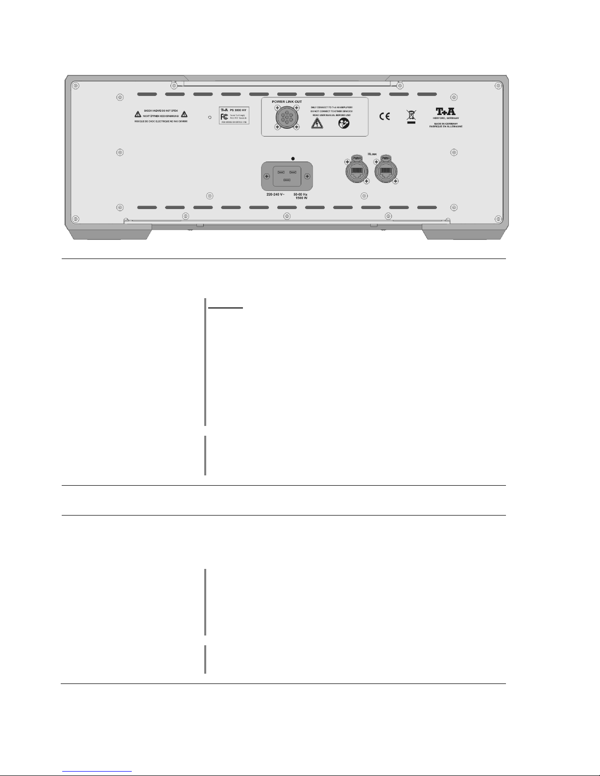
POWER LINK OUT
Socket for connecting an A 3000 HV
Caution!
This socket must only be used to connect a A 3000 HV power amplifier
or a PA 3100 HV integrated amplifier. It must not be used to connect any
other device!
Very high currents can flow through the Power Link connection, and high voltages
are present. For this reason the connection between the two devices must only be
made using the Power Link cable supplied by .
The device features a safety power-off circuit which cuts off any voltage at the
contacts when the Power Link cable is disconnected. Nevertheless, these
contacts should not be touched, both to avoid corrosion of the parts and in the
interests of personal safety. Do not remove the retainer collars or the Power Link
cable unless all the components are disconnected from the mains.
The Power Link cable supplied in the set is designed to suit an installation with
the devices stacked one upon the other. For different arrangements - such as a
side-by-side installation - the accessory range includes a long cable (Part.
No.: 4084-99401).
H LINK
Control input for connection to devices with an H LINK output.
Mains input
This socket is for mains connection.
For correct connection refer to the sections 'Installation and wiring' and
'Safety notes'.
Caution:
The PS 3000 HV must be connected to the mains supply with the same phase
as the A 3000 HV to which it is connected.
The PS 3000 HV must never be connected to any device whose purpose is to
condition the mains supply, e.g. power conditioners or similar, which are wired
in series with the PS 3000 HV.
If you intend not to use the device for a long period, it should be disconnected
from the mains socket, i.e. the mains plug should be withdrawn from the wall
socket
Page 25
25
Installation and wiring
Carefully unpack the unit and store the original packing material carefully. The
carton and packing are specially designed for this unit and will be needed again
if you wish to move the equipment at any time.
If you have to transport the device, it must always be carried or sent in its original
packaging in order to prevent damage and defects.
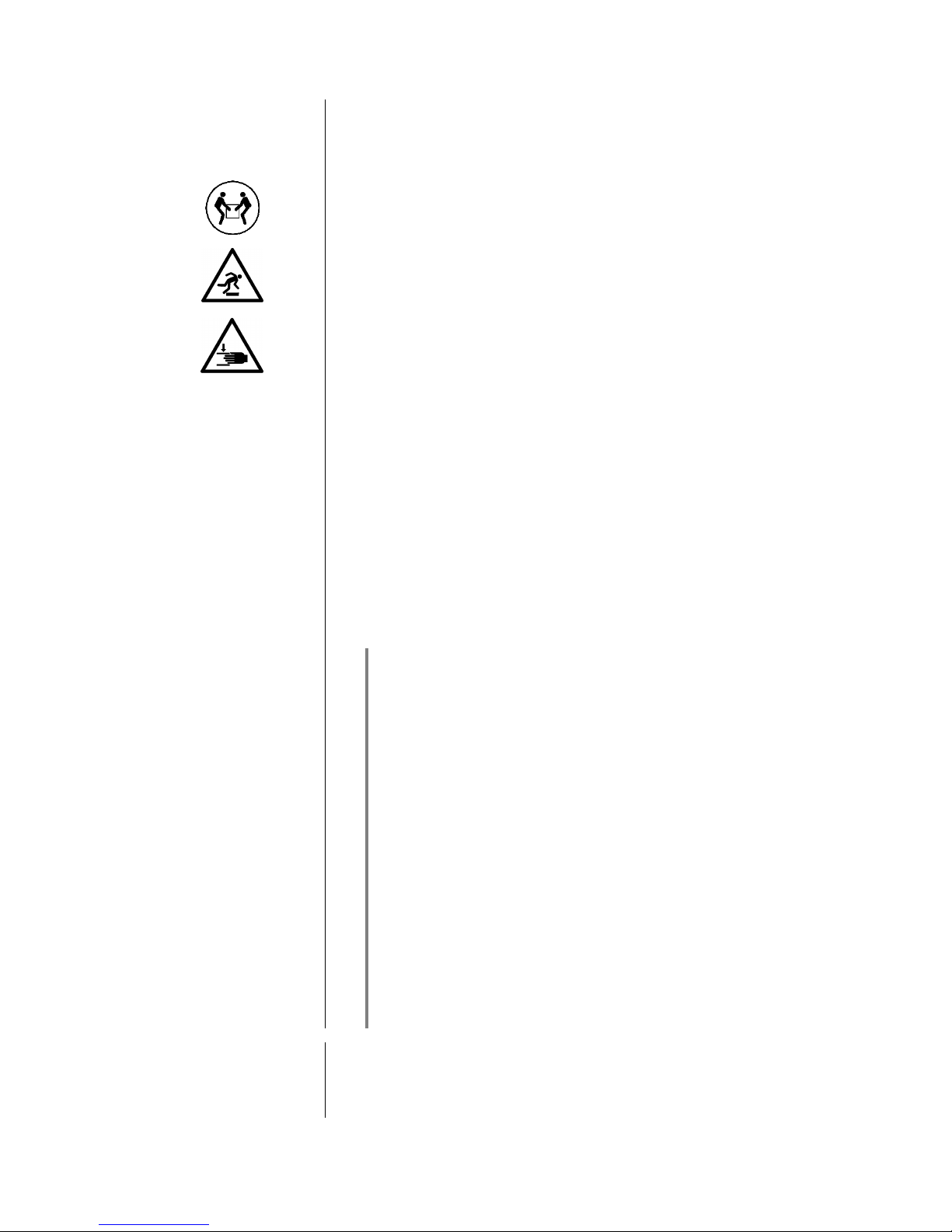
The device is extremely heavy - caution is required when unpacking and
transporting it. Always lift and transport the device with two persons.
Legal requirements pertaining to the lifting of heavy loads prohibit the transport
of the device by women.
Ensure that you have a firm, secure hold on the device. Do not let it fall. Wear
safety footwear when moving the device. Take care not to stumble. Ensure an
unobstructed area of movement by removing obstacles and possible hindrances
from the route.
Take care when lowering the device! To avoid your fingers being crushed,
ensure that they are not trapped between the device and the support surface.
If the unit gets very cold (e. g. when being transported), condensation may form
inside it. Please do not switch it on until it has had plenty of time to warm up to
room temperature, so that any condensation evaporates completely.
If the device has been in storage, or has not been used for a protracted period
(> two years), it is essential to have it checked by a specialist technician before
re-use.
Before placing the unit on sensitive laquer or wood surfaces please check the
compatibility of the surface and the unit's feet on a non visible point and if
necessary use an underlay. We recommend a surface of stone, glass, metal or
the like.
The unit should be placed on a rigid, level base (See also chapter “Safety
notes”). When placing the unit on resonance absorbers or anti-resonant
components make sure that the stability of the unit is not reduced.
The unit should be set up in a well ventilated dry site, out of direct sunlight and
away from radiators.
The unit must not be located close to heat-producing objects or devices, or
anything which is heat-sensitive or highly flammable.
Mains and loudspeaker cables, and also remote control leads must be kept as
far away as possible from signal leads and antenna cables. Never run them
over or under the unit.
Notes on connections:
Always tighten the Power Link plug fully. Check carefully that the plug is not
tilted or skewed when it is screwed in place. Note the markings on the socket
and plug (see wiring diagram in Appendix A).
Do not switch the PS 3000 HV on unless the Power Link cable is properly
inserted and tightened.
The H LINK socket of the integrated amplifier should be connected to the
H LINK socket of the source devices (see wiring diagram in Appendix A).
The device is intended to be connected to mains outlet with protective earth
connector. Please connect it only with the mains cable supplied to a properly
installed mains outlet with protective earth connector. To achieve maximum
possible interference rejection the mains plug must be connected to the mains
socket in such a way that phase is connected to the mains socket contact
marked with a dot ().
Do not use switchable mains sockets, such as switched multiple-outlet
sockets.
Brief interruptions in the power supply may cause the mains fuse fitted to the
PS 3000 HV to trip.
It is essential to check that the mains socket you wish to use can supply the
power required for the equipment.
(The power consumed by the PS 3000 HV in conjunction with the A 3000 HV /
PA 3100 HV can be up to 3300 W!)
When you have completed the wiring of the system switch the system on.
If you encounter problems when setting up and using the integrated amplifier for
the first time please remember that the cause is often simple, and equally
simple to eliminate. Please refer to the section of these instructions entitled
'Trouble shooting'.
Page 26

26
Safety notes
For your own safety please consider it essential to read these operating
instructions right through, and observe in particular the notes regarding setting
up, operation and safety.
Installation
Please consider the weight of the device. Never place the device on an
unstable surface; the machine could fall off, causing serious or even fatal injury.
Many injuries, especially to children, can be avoided if the following simple
safety precautions are observed:
- Use only such items of furniture which can safely bear the weight of the
device.
- Ensure that the device does not project beyond the edges of the supporting
furniture.
- Do not place the device on tall furniture (e.g. bookshelves) without securely
anchoring both items, i.e. furniture and device.
- Explain to children the hazards involved in climbing on furniture to reach the
device or its controls.
When installing the unit on a shelf or in a cupboard it is essential to provide an
adequate flow of cooling air, to ensure that the heat produced by the unit is
dissipated effectively. Any heat build-up will shorten the life of the unit and could
be a source of danger. Be sure to leave a free space of approx.. 10 cm around
the unit for ventilation.
If the system components are to be stacked then the amplifier must be the top
unit. Do not place any object on the top cover.
The unit must be set up in such a way that none of the connections can be
touched directly (especially by children). Be sure to observe the notes and
information in the section 'Installation and Wiring'.
Connection
The terminals (marked with the -symbol) can carry high voltages.
Always avoid touching terminals and sockets and the conductors of cables
connected to them. Unless ready-made cables are used, all cables connected
to these terminals and sockets must always be deployed by a trained person.
Power supply
The device is intended to be connected to mains outlet with protective earth
connector. Please connect it only with the mains cable supplied to a properly
installed mains outlet with protective earth connector.
The power supply required for this unit is printed on the mains supply socket.
The unit must never be connected to a power supply which does not meet these
specifications. If the unit is not to be used for a long period disconnect it from
the mains supply at the wall socket.
Mains leads / Mains plug
Mains leads must be deployed in such a way that there is no danger of damage
to them (e. g. through persons treading on them or from furniture). Take
particular care with plugs, distribution panels and connections at the device.
Unplugging the mains plug will disconnect the device from the mains for service
and repair. Please make sure that the mains plug is easily accessible.
Enclosure openings
Liquid or particles must never be allowed to get inside the unit through the
ventilation slots. Mains voltage is present inside the unit, and any electric shock
could cause serious injury or death. Never exert undue force on mains
connectors.
Protect the unit from drips and splashes of water; never place flower vases or
fluid containers on the unit.
Do not place naked flame sources, such as candle lights on the device.
Supervision of device
operation
Like any other electrical appliance this device should never be used without
proper supervision. Take care to keep the unit out of the reach of small children.
Service, Damage
The case should only be opened by a qualified specialist technician. Repairs
and fuse replacements should be entrusted to an authorised specialist
workshop. With the exception of the connections and measures described in
these instructions, no work of any kind may be carried out on the device by
unqualified persons.
If the unit is damaged, or if you suspect that it is not functioning correctly,
immediately disconnect the mains plug at the wall socket, and ask an
authorised specialist workshop to check it.
Over voltage
The unit may be damaged by excess voltage in the power supply, the mains
circuit or in aerial systems, as may occur during thunderstorms (lightning
strikes) or due to static discharges.
Special power supply units and excess voltage protectors such as the
'Power Bar' mains distribution panel offer some degree of protection from
Page 27
27
damage to equipment due to the hazards described above.
However, if you require absolute security from damage due to excess voltage,
the only solution is to disconnect the unit from the mains power supply and any
aerial systems.
To avoid the risk of damage by overvoltages we recommend to disconnect all
cables from this device and your HiFi system during thunderstorms.
All mains power supply and aerial systems to which the unit is connected must
meet all applicable safety regulations and must be installed by an approved
electrical installer.
Approved usage
The device is designed to operate in a temperate climate. The range of
permissible operating temperatures is +10 … +35°C. This device is designed
exclusively for reproducing sound and/or pictures in the domestic environment.
It is to be used in a dry indoor room which meets all the recommendations
stated in these instructions.
Where the equipment is to be used for other purposes, especially in the medical
field or any field in which safety is an issue, it is essential to establish the unit’s
suitability for this purpose with the manufacturer, and to obtain prior written
approval for this usage.
Approval and conformity
with EC directives
In its original condition the unit meets all currently valid European regulations. It
is approved for use as stipulated within the EC.
By attaching the CE symbol to the unit declares its conformity the EC
directives (See page 17) and the national laws based on those directives.
The original, unaltered factory serial number must be present on the outside of
the unit and must be clearly legible! The serial number is a constituent part of
our conformity declaration and therefore of the approval for operation of the
device. The serial numbers on the unit and in the original documentation
supplied with it (in particular the inspection and guarantee certificates), must not
be removed or modified, and must correspond.
Infringing any of these conditions invalidates conformity and approval, and
the unit may not be operated within the EC. Improper use of the equipment
makes the user liable to penalty under current EC and national laws.
Any modifications or repairs to the unit, or any other intervention by a workshop
or other third party not authorised by , invalidates the approval and
operational permit for the equipment.
Only genuine accessories may be connected to the unit, or such auxiliary
devices which are themselves approved and fulfil all currently valid legal
requirements.
When used in conjunction with auxiliary devices or as part of a system this unit
may only be used for the purposes stated in the section 'Approved usage'.
Disposing of this
product
The only permissible method of disposing of this product is to take it to your
local collection centre for electrical waste.
FCC Information to the
user
(for use in the United States of
America only)
Class B digital device – instructions:
Note: This equipment has been tested and found to comply with the limits for a
Class B digital device, pursuant to Part 15 of the FCC Rules. These limits are
designed to provide reasonable protection against harmful interference in a
residential installation. This equipment generates, uses and can radiate radio
frequency energy and, if not installed and used in accordance with the
instructions, may cause harmful interference to radio communications.
However, there is no guarantee that interference will not occur in a particular
installation. If this equipment does cause harmful interference to radio or
television reception, which can be determined by turning the equipment off and
on, the user is encouraged to try to correct the interference by one or more of
the following measures:
- Reorient or relocate the receiving antenna.
- Increase the separation between the equipment and receiver.
- Connect the equipment into an outlet on a circuit different form that to which
the receiver is connected.
- Consult the dealer or an experienced radio/TV technician for help.
Page 28

28
Trouble shooting
Many problems have a simple cause and a correspondingly simple solution. The following section describes a few
difficulties you may encounter, and the measures you need to take to cure them. If you find it impossible to solve a
problem with the help of these notes please disconnect the unit from the mains and ask your authorised specialist
dealer for advice.
Machine does not switch
on.
Cause 1:
Mains lead not plugged in correctly.
Remedy:
Check connection, push connector in firmly.
Cause 2:
Powerful interference or electro-static discharge has disrupted the device’s
processor.
Remedy:
Disconnect the unit from the mains for at least one minute.
Cause 3:
Mains fuse burned out.
Remedy:
Have the mains fuse replaced by an authorised specialist workshop. The rating
of the replacement fuse must agree with the specification printed on the unit.
Cause 4:
The Power Link cable is not correctly screwed in place.
Remedy:
Check the Power Link connection: the retaining collars must be firmly tightened.
Cause 5:
The A 3000 HV / PA 3100 HV connected is defective, and cannot switch the
PS 3000 HV on.
Remedy:
Please contact your local specialist workshop.
Cause 6:
The soft start circuit has detected a fault and the LED flashes red also after the
device was disconnected from mains for about 10 seconds.
Remedy:
Please contact your local specialist workshop.
When the A 3000 HV is
turned off, the PS 3000 HV
does not switch off
immediately
Cause:
The HV Link cable is not correctly connected.
Remedy:
Check the HV Link connection. Push the plugs firmly into the sockets.
The LED flashes orange
continuously
Cause:
The capacitors in the A 3000 HV / PA 3100 HV must be discharged before the
PS 3000 HV can be switched on.
Remedy:
Switch the A 3000 HV / PA 3100 HV off, then wait about five minutes for the
capacitors to become discharged.
Page 29

29
Notes on energy saving
General information
The PS 3000 HV satisfies the requirements of the latest directives concerning
energy-saving measures (EuP directive). The modern design of the mains
power supply makes an important contribution to this.
The internal micro-processor constantly ensures that sub-assemblies which are
not currently required are automatically switched off. The micro-processor itself
operates in stand-by mode at a relatively low clock speed.
In stand-by mode the current drain of the PS 3000 HV is less than 0.5 Watt.
If you intend not to use the device for a long period, it should be discon-nected
from the mains socket, i.e. the mains plug should be withdrawn from the wall
socket.
Page 30
30
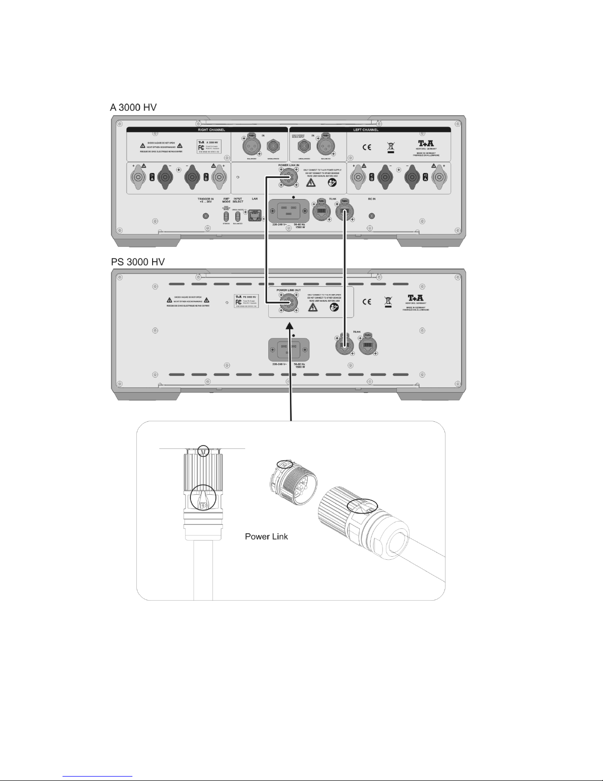
Anhang / Appendix A
Anschluss-Schema / Wiring diagram
*1 Hinweis:
Beim Anschließen der Power Link Verbindung sollten die Geräte vom Netz getrennt sein. Die Steckverbinder haben zur
Sicherung einen Überwurfring, welcher mit der Gerätebuchse fest verschraubt wird. Um das Power Link Kabel an
PS 3000 HV, A 3000 HV und PA 3100 HV anzuschließen halten Sie den Stecker mit der Markierung (siehe Abbildung
oben) nach oben und schrauben Sie den Überwurf fest auf die Gerätebuchse. Der Dichtungsring darf nicht mehr zu
sehen sein.
*1 Note:
Always disconnect the devices from the mains before connecting the Power Link cable to them. For security each
connector is fitted with a cap screw which should be screwed tightly to the socket. To connect the Power Link cable to
the PS 3000 HV, A 3000 HV or the PA 3100 HV, hold the plug with the mark facing up (see top picture) and screw the
cap screw firmly onto the socket on the machine. The sealing ring must be completely hidden.
Page 31
31
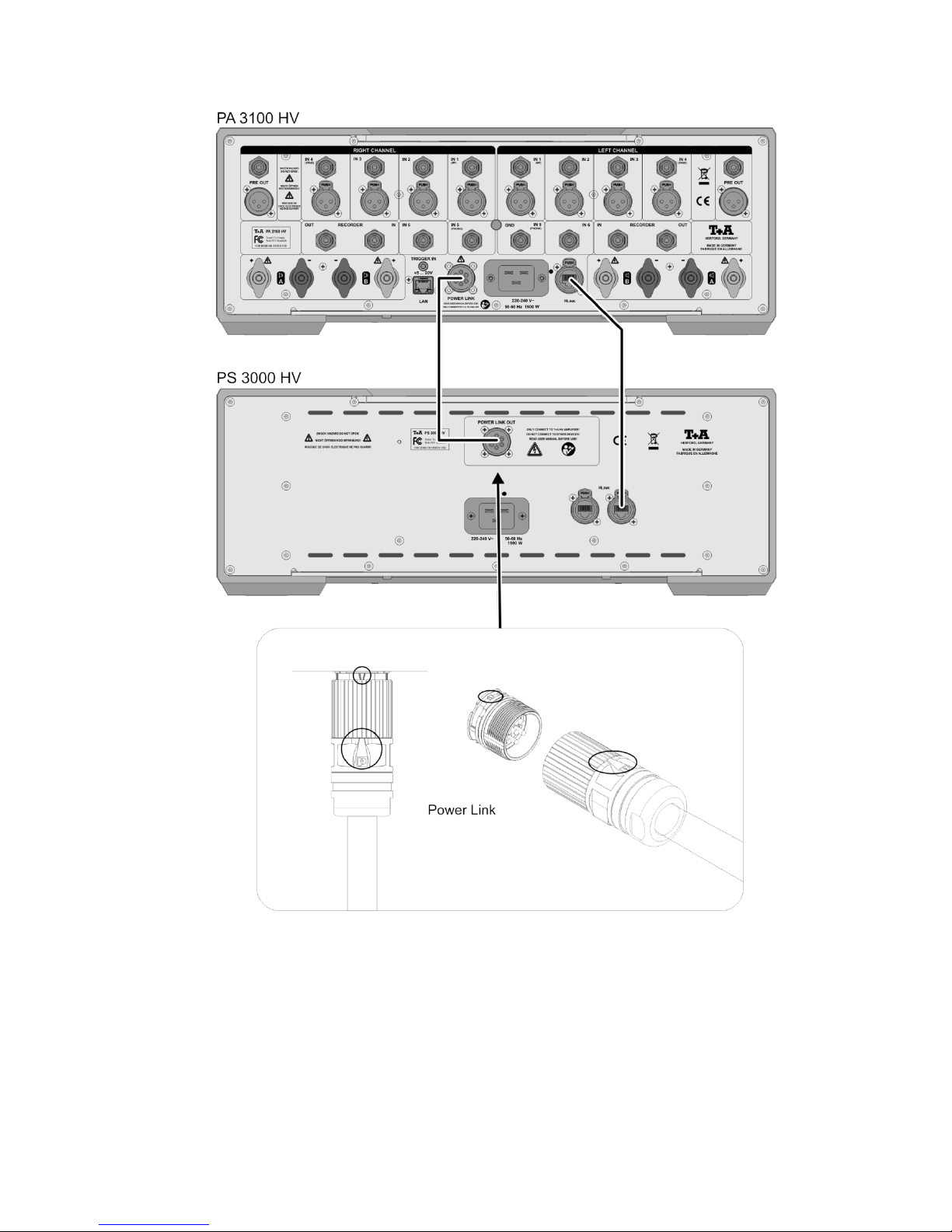
Anschluss-Schema / Wiring diagram
*1 Hinweis:
Beim Anschließen der Power Link Verbindung sollten die Geräte vom Netz getrennt sein. Die Steckverbinder haben zur
Sicherung einen Überwurfring, welcher mit der Gerätebuchse fest verschraubt wird. Um das Power Link Kabel an
PS 3000 HV, A 3000 HV und PA 3100 HV anzuschließen halten Sie den Stecker mit der Markierung (siehe Abbildung
oben) nach oben und schrauben Sie den Überwurf fest auf die Gerätebuchse. Der Dichtungsring darf nicht mehr zu
sehen sein.
*1 Note:
Always disconnect the devices from the mains before connecting the Power Link cable to them. For security each
connector is fitted with a cap screw which should be screwed tightly to the socket. To connect the Power Link cable to
the PS 3000 HV, A 3000 HV or the PA 3100 HV, hold the plug with the mark facing up (see top picture) and screw the
cap screw firmly onto the socket on the machine. The sealing ring must be completely hidden.
Page 32

32
Technische Daten / Technical Specifications
Netzteilsiebung / PWR-Supply reservoir capacity
240000 µF
Netzanschluss / PWR requirement 230 V version
115 V version
220 - 240 V~, 50-60 Hz
110 - 115 V~, 50-60 Hz
Leistungsaufnahme
Power con-sumption
max.
Standby
1500 W
0,5 W
Abmessungen /
Dimensions
H x B x T /
H x W x D
17 cm x 46 cm x 46 cm
Gewicht / Weight
38 kg
Zum Lieferumfang gehören
Supplied standard accessories
Netzkabel / Power cord
Power Link Kabel / Power Link cord
Betriebsanleitung / User manual
Technische Änderungen vorbehalten / We reserve the right to alter specifications
Page 33

33
Page 34

elektroakustik GmbH & Co. KG
Herford
Deutschland * Germany
 Loading...