

Page 1

Bestell Nr. / Order no. 9103 – 0521 DE / UK
Betriebsanleitung
User manual
Phonomodul / Phono Module
E-Series 1000
PHE MM
PHE MC
Page 2

2
Page 3

3
Seite / Page
Deutsch ........................................................ 4
English ....................................................... 13
Page 4

4
Willkommen.
Wir freuen uns, dass Sie sich für ein -Produkt entschieden haben. Mit dem High-End
Phono-Vorverstärkermodul PHE MM / MC für Geräte der E-Serie (1000), haben Sie eine
hochwertige HiFi-Komponente der Spitzenklasse erworben, bei dessen Konzeption und
Entwicklung den Wünschen des anspruchsvollen Musikliebhabers oberste Priorität eingeräumt
wurde.
Die innovativen Problemlösungen, die solide, durchdachte Konstruktion und die verwendeten
hochwertigen Materialien werden dazu beitragen, dass dieses Gerät höchsten Anforderungen
und Ansprüchen über viele Jahre genügen wird.
Eine genaue Qualitätsprüfung aller Materialien, die sorgfältige Produktion durch hochqualifizierte
Fachkräfte und eine rechnergesteuerte, vollautomatisierte Endkontrolle gewährleisten die hohe
Produktqualität und die Einhaltung aller Spezifikationen.
In unserer Geräteproduktion wird der Einsatz aller umwelt- und gesundheitsgefährdenden Stoffe,
wie z. B. chlorhaltige Lösungsmittel und FCKWs, vermieden.
Darüber hinaus verzichten wir wo irgend möglich auf Kunststoffe (insbesondere auf PVC) als
Konstruktionselement. Stattdessen wird auf Metalle oder andere unbedenkliche Materialien
zurückgegriffen, die einerseits gut recycelbar sind und andererseits eine sehr gute elektrische
Abschirmung ergeben.
Wir bedanken uns für Ihr Vertrauen und wünschen Ihnen viel Freude und Hörvergnügen.
elektroakustik GmbH & Co KG
Alle verwendeten Bauteile entsprechen den geltenden deutschen und europäischen
Sicherheitsnormen und -standards. Zu Ihrer eigenen Sicherheit sollten Sie bitte
unbedingt diese Betriebsanleitung vollständig lesen und insbesondere die
Aufstellungs-, Betriebs- und Sicherheitshinweise genau befolgen.
Page 5

5
Inhaltsverzeichnis
Installation und Einstellung
Wichtige Hinweise ................................................................................................... 6
Allgemeines ............................................................................................................ 7
Betrieb
Einstellmöglichkeiten am Phono-Modul MM
Einstellen der Eingangsempfindlichkeit ................................................................... 8
Einstellen der Eingangskapazität ............................................................................. 9
Einstellmöglichkeiten am Phono-Modul MC
Einstellen der Eingangsempfindlichkeit .................................................................. 10
Einstellen der Eingangsimpedanz .......................................................................... 11
Sonstiges
Betriebsstörungen .................................................................................................. 12
Anhang
Einbaulage des Phonomoduls ................................................................................ 24
Anschluss-Schema ................................................................................................ 26
Technische Daten .................................................................................................. 27
In der Anleitung verwendete Symbole
Achtung!
Mit diesem Symbol gekennzeichnete Textstellen enthalten wichtige Hinweise, die für einen
problemlosen und sicheren Betrieb des Gerätes unbedingt beachtet werden müssen.
Dieses Symbol markiert Textpassagen, die Ihnen zusätzliche Hinweise und
Hintergrundinformation geben und das Verständnis erleichtern sollen.
Page 6

6
Wichtige Hinweise
Einbau / Ausbau
Achtung!
Der Ein- bzw. Ausbau des Phonomoduls darf nur durch oder eine
autorisierte Fachwerkstatt erfolgen.
Die Installation ist in der Service-Note
„S0127_PHE_MM_MC_Installation_E1000“ im Detail beschrieben.
Page 7
7
Allgemeines
Einstellungen
Von entscheidender Bedeutung für die Klangqualität eines
Tonabnehmersystems ist die genaue Anpassung. Deshalb ist das
Phonomodul so konzipiert, dass es durch Codierschalter perfekt an alle
gängigen Tonabnehmersysteme angepasst werden kann.
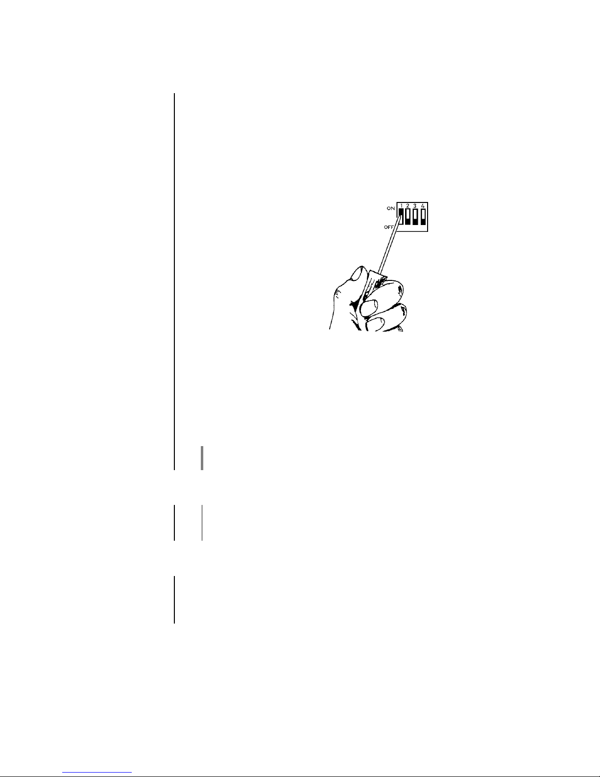
Mit Hilfe eines kleinen Schraubendrehers können die einzelnen Schalter
in die Position „ON“ oder „OFF“ geschoben werden.
Die genaue Einstellung der Eingangsempfindlichkeit sowie die perfekte
Anpassung erfolgt gemäß Tabellen 1 bis 4.
Alle im Folgenden beschriebenen Einstellungen des Phonomoduls
müssen bei geöffnetem Gehäusedeckel vorgenommen werden.
Achten Sie bitte darauf, dass bei beiden Kanälen gleiche
Einstellwerte eingestellt werden.
Anschluss
Auf Seite 26 ist der Anschluss eines Plattenspielers an den R 1000 E
dargestellt. Achten Sie bitte auf die zusätzliche Masseverbindung um
Brummen und Störgeräusche zu eliminieren.
Betrieb
Reduzieren Sie die Lautstärke des R 1000 E auf einen geringen Wert.
Wählen Sie die Quelle IN 3 (PH) aus und starten die Wiedergabe am
Plattenspieler. Anschließend stellen Sie die gewünschte Lautstärke am
R 1000 E ein.
Page 8
8
Einstellmöglichkeiten am Phono-Modul MM
Schalterpositionen
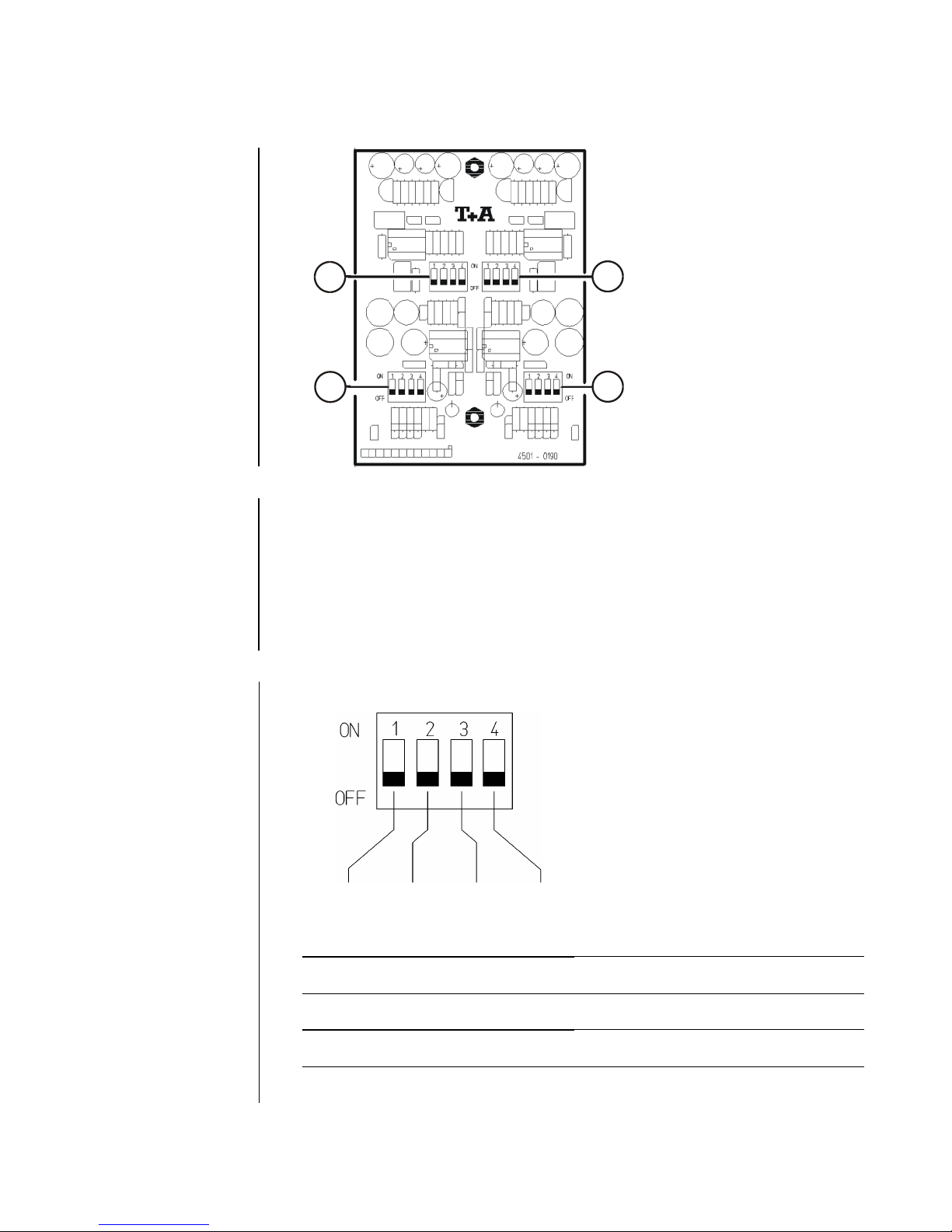
1L
1R
2L
2R
Einstellen der
Eingangsempfindlichkeit
(Gain)
Mit den Codier-Schaltern "1" wird die gewünschte Eingangsempfindlichkeit für den linken (1L) und rechten Kanal (1R) gemäß
Tabelle 1 eingestellt.
Die benötigten Daten entnehmen Sie den Herstellerangaben des
Tonabnehmersystems. Wählen Sie den Wert, der den Herstellerangaben
am nächsten liegt. Sollten Ihnen keine Herstellerangaben vorliegen,
stellen Sie zunächst eine Empfindlichkeit von 3.5 mV ein. Dieses
entspricht der Werkseinstellung.
Eingangsempfindlichkeit
Schalterstellung
Empfindlichkeit [mV]
OFF
OFF
OFF
OFF
6,0
…
10,0
OFF
OFF
OFF
ON
3,5
…
6,0
OFF
OFF
ON
OFF
2,5
…
3,5
OFF
ON
OFF
OFF
1,5
…
2,5
ON
OFF
OFF
OFF
1,0
…
1,5
Tabelle 1
Page 9
9
Einstellen der
Eingangskapazität
(Impedance)
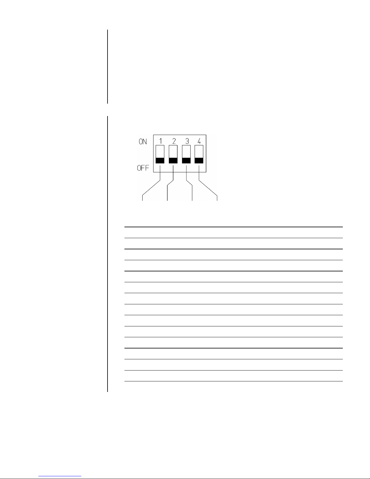
Die Einstellung erfolgt durch die Codier-Schalter "2" für den linken (2L)
und rechten (2R) Kanal.
Die benötigten Daten entnehmen Sie den Herstellerangaben des
Tonabnehmersystems. Wählen Sie den Wert, der den Herstellerangaben
am nächsten liegt.
Beachten Sie, dass auch das Phono-Anschlusskabel eine Kapazität
darstellt, die je nach Hersteller zwischen 50 und 200 pF liegt. Es müssen
unbedingt beide Kanäle gleich eingestellt werden. Sollten Ihnen keine
Herstellerangaben vorliegen, stellen Sie zunächst eine Eingangskapazität von 120 pF ein. Dieses entspricht der Werkseinstellung.
Eingangskapazität
Schalterstellung
Eingangskapazität [pF]
OFF
OFF
OFF
OFF
<
120 pF
OFF
OFF
OFF
ON
121 pF
...
140 pF
OFF
OFF
ON
OFF
141 pF
...
160 pF
OFF
OFF
ON
ON
161 pF
...
190 pF
OFF
ON
OFF
OFF
191 pF
...
220 pF
OFF
ON
OFF
ON
221 pF
...
240 pF
OFF
ON
ON
OFF
241 pF
...
260 pF
OFF
ON
ON
ON
261 pF
...
290 pF
ON
OFF
OFF
OFF
291 pF
...
340 pF
ON
OFF
OFF
ON
341 pF
...
360 pF
ON
OFF
ON
OFF
361 pF
...
380 pF
ON
OFF
ON
ON
381 pF
...
400 pF
ON
ON
OFF
OFF
401 pF
...
440 pF
ON
ON
OFF
ON
441 pF
...
460 pF
ON
ON
ON
OFF
461 pF
...
480 pF
ON
ON
ON
ON
481 pF
...
500 pF
Tabelle 2
Page 10

10
Einstellmöglichkeiten am Phono-Modul MC
Schalterpositionen
1L
1R
2L
2R
Einstellen der
Eingangsempfindlichkeit
(Gain)
Mit den Codier-Schaltern "1" wird die gewünschte Eingangsempfindlichkeit für den linken (1L) und rechten Kanal (1R) gemäß
Tabelle 3 eingestellt.
Die benötigten Daten entnehmen Sie den Herstellerangaben des
Tonabnehmersystems. Wählen Sie den Wert, der den Herstellerangaben
am nächsten liegt. Es müssen unbedingt beide Kanäle gleich eingestellt
werden. Sollten Ihnen keine Herstellerangaben vorliegen, stellen Sie
zunächst eine Empfindlichkeit von 500 V ein. Dieses entspricht der
Werkseinstellung
Eingangsempfindlichkeit
Empfindlichkeit [V]
OFF
OFF
OFF
OFF
>
2000 V
OFF
OFF
OFF
ON
1200 V
...
2000 V
OFF
OFF
ON
OFF
800 V
...
1200 V
OFF
OFF
ON
ON
600 V
...
800 V
OFF
ON
OFF
OFF
400 V
...
600 V
OFF
ON
ON
ON
300 V
...
400 V
ON
OFF
OFF
OFF
200 V
...
300 V
ON
ON
OFF
OFF
160 V
...
200 V
ON
ON
ON
ON
100 V
...
160 V
Hinweis: 1000 µV entsprechen 1 mV Tabelle 3
Page 11

11
Einstellen der
Eingangsimpedanz
(Impedance)
Die Einstellung erfolgt durch die Codier-Schalter "2" für den linken (2L)
und rechten (2R) Kanal.
Die benötigten Daten entnehmen Sie den Herstellerangaben des
Tonabnehmersystems.
Wählen Sie den Wert, der den Herstellerangaben am nächsten liegt. Es
müssen unbedingt beide Kanäle gleich eingestellt werden.
Sollten Ihnen keine Herstellerangaben vorliegen, stellen Sie zunächst
eine Eingangsimpedanz von 100 ein. Dieses entspricht der
Werkseinstellung.
Eingangsimpedanz
Eingangsimpedanz []
OFF
OFF
OFF
OFF
450
...
650
OFF
OFF
OFF
ON
200
...
449
OFF
OFF
ON
OFF
130
...
199
OFF
OFF
ON
ON
85
...
129
OFF
ON
OFF
OFF
50
...
84
OFF
ON
ON
OFF
30
...
49
ON
OFF
OFF
OFF
20
...
29
ON
ON
OFF
OFF
16
...
19
ON
ON
ON
ON
<
15
Tabelle 4
Page 12

12
Betriebsstörungen
Viele Betriebsstörungen haben eine einfache Ursache, die sich leicht beheben lässt. Im
folgenden Abschnitt sind einige mögliche Störungen sowie Maßnahmen zu deren Behebung
aufgeführt. Sollte sich eine aufgetretene Störung durch diese Hinweise nicht beheben lassen, so
wenden Sie sich bitte und an eine -Fachwerkstatt.
Die Wiedergabe ist im
Vergleich zu anderen
Eingangsquellen zu leise
bzw. zu laut.
Ursache:
Die Empfindlichkeit ist nicht optimal angepasst.
Abhilfe:
Verändern Sie die Einstellung für die Empfindlichkeit
(Sensitivity) beider Kanäle.
Der Klang ist dumpf bzw.
überspitzt.
Ursache:
Die Eingangskapazität ist nicht optimal angepasst.
Abhilfe:
Verändern Sie die Einstellung für die Eingangskapazität (Input
Capacity) beider Kanäle.
Das Audio-Signal ist
extrem leise, zusätzlich ist
das Signal verrauscht.
Das System kann nicht
angepasst werden.
Ursache:
Tonabnehmersystem ist ein MC-System, das Phonomodul ist
jedoch eine MM Version.
Abhilfe:
Tauschen Sie das MM-Modul gegen ein MC-Modul aus.
Das Audio-Signal wird bei
lauten Stellen verzerrt.
Das System kann nicht
angepasst werden.
Ursache
Tonabnehmersystem ist ein MM-System., das Phonomodul ist
jedoch eine MC Version.
Abhilfe:
Tauschen Sie das MC-Modul gegen ein MM-Modul aus.
Lautes Brummen aus den
Lautsprechern.
Ursache 1:
Schlechter Kontakt der Cinch-Stecker oder ein defektes
Cinchkabel.
Abhilfe:
Überprüfen Sie bitte genau alle Steckverbindungen und
Verbindungskabel.
Ursache 2:
Erdungskabel zwischen R 1000 E und Plattenspieler fehlt.
Abhilfe:
Stellen Sie über die Erdungsklemmen eine Masseverbindung
zwischen Plattenspieler und R 1000 E her.
Page 13

13
English
Page 14

14
Welcome.
We are delighted that you have decided to purchase a product. With the phono-module
PHE MM / MC for your E-Series (1000) device you have acquired a top-quality piece of
equipment which has been designed and developed with the wishes of discerning listeners as
absolute top priority.
This system represents our very best efforts at designing practical electronic equipment
incorporating solid quality, user-friendly operation and a specification and performance which
leaves nothing to be desired.
All these factors contribute to a piece of equipment which will satisfy your highest demands and
your most searching requirements for a period of many years. All the components we use meet
the German and European safety norms and standards which are currently valid. All the
materials we use are subject to painstaking quality monitoring.
At all stages of production we avoid the use of substances which are environmentally unsound or
potentially hazardous to health, such as chlorine-based cleaning agents and CFCs.
We also aim to avoid the use of plastics in general, and PVC in particular, in the design of our
products. Instead we rely upon metals and other non-hazardous materials; metal components
are ideal for recycling, and also provide effective electrical screening.
Our range of accessories includes high-quality cables and connectors.
We would like to take this opportunity to thank you for the faith you have shown in our company
by purchasing this product, and wish you many hours of enjoyment and sheer listening pleasure.
elektroakustik GmbH & Co KG
All the components we use meet the European safety norms and standards which are
currently valid. The operation instructions, the connection guidance and the safety notes
are for your own good - please read them carefully and observe them at all times.
Page 15

15
Contents
Installation and Adjustment
Safety notes ............................................................................................................ 16
Settings ................................................................................................................... 17
Operation
Adjustment facilities on the Phono module MM
Setting the input sensitivity ...................................................................................... 18
Setting the input capacity ....................................................................................... 19
Adjustment facilities on the Phono module MC
Setting the input sensitivity ...................................................................................... 20
Setting the input resistance .................................................................................... 21
General
Troubleshooting ..................................................................................................... 22
FCC Information to the user .................................................................................... 23
Appendix
Mounting position Phono module ............................................................................ 24
Wiring diagram ........................................................................................................ 26
Specification............................................................................................................ 27
Symbols used in these instructions
Caution!
Text passages marked with this symbol contain important information which must be
observed if the machine is to operate safely and without problems.
This symbol marks text passages which provide supplementary notes and background
information; they are intended to help the user understand how to get the best out of the
machine.
Page 16

16
Safety notes
Caution
Installation and de-installation of the Phono Preamplifier module must be
carried out by or one of our authorized dealers.
The installation procedure is described in detail in service note
“S0127_PHE_MM_MC_Installation_E1000“.
Page 17

17
Settings
Adjustments
Accurate matching is crucially important to the sound quality produced by
a pick-up system. For this reason the phono module features a set of
miniature switches which enable the user to adjust it perfectly to suit all
current pick-up systems.
The individual switches can be moved to the “ON“ or “OFF“ position using
a small screwdriver.
The input sensitivity, capacitance and impedance should be adjusted as
shown in Tables 1 to 4.
All the following settings only can be altered with the top cover removed.
It is essential to set the same value for both channels.
Connections
The connection of a turntable to the R 1000 E is shown on page 26.
Please make sure to connect the additional grounding lead of your
turntable to avoid hum and noise.
Operation
Please turn down the volume to a low level and then select „Phono“ as
listening source. Start playback of a record and adjust the volume to the
desired level.
Page 18

18
Adjustment facilities on the Phono module MM
Switch positions
1L
1R
2L
2R
Setting the input
sensitivity
(Gain)
Miniature switches „1“ are used to set the desired input sensitivity for the
left (1L) and right (1R) channels as shown in Table 1.
The information you need for this will be included in the manufacturer’s
specification for the pick-up system you intend to use. Select the value
which is closest to the manufacturer’s stated figure. It is essential to set
the same value for both channels.
If you do not have access to the manufacturer’s specification, a good
starting point for sensitivity is 3.5 mV. This is the factory default setting.
Input sensitivity
Input sensitivity [mV]
OFF
OFF
OFF
OFF
6,0
…
10,0
OFF
OFF
OFF
ON
3,5
…
6,0
OFF
OFF
ON
OFF
2,5
…
3,5
OFF
ON
OFF
OFF
1,5
…
2,5
ON
OFF
OFF
OFF
1,0
…
1,5
Table 1
Page 19

19
Setting the input
capacitance
(Impedance)
Miniature switches „2“ are used to set the desired input capacitance for
the left (2L) and right (2R) channels. The information you need for this
will be included in the manufacturer’s specification for the pick-up system
you intend to use. Select the value which is closest to the manufacturer’s
stated figure. Note that the phono connecting lead also represents a
capacitance in the range 50 to 200 pF, depending on the manufacturer. It
is essential to set the same value for both channels. If you do not have
access to the manufacturer’s specification, a good starting point for input
capacitance is 120 pF. This is the factory default setting.
OFF
OFF
OFF
OFF
<
120 pF
OFF
OFF
OFF
ON
121 pF
...
140 pF
OFF
OFF
ON
OFF
141 pF
...
160 pF
OFF
OFF
ON
ON
161 pF
...
190 pF
OFF
ON
OFF
OFF
191 pF
...
220 pF
OFF
ON
OFF
ON
221 pF
...
240 pF
OFF
ON
ON
OFF
241 pF
...
260 pF
OFF
ON
ON
ON
261 pF
...
290 pF
ON
OFF
OFF
OFF
291 pF
...
340 pF
ON
OFF
OFF
ON
341 pF
...
360 pF
ON
OFF
ON
OFF
361 pF
...
380 pF
ON
OFF
ON
ON
381 pF
...
400 pF
ON
ON
OFF
OFF
401 pF
...
440 pF
ON
ON
OFF
ON
441 pF
...
460 pF
ON
ON
ON
OFF
461 pF
...
480 pF
ON
ON
ON
ON
481 pF
...
500 pF
Table 2
Page 20

20
Adjustment facilities on the Phono module MC
Switch positions
1L
1R
2L
2R
Setting the input
sensitivity
(Gain)
Miniature switches „1“ are used to set the desired input sensitivity for the
left (1L) and right (1R) channels as shown in Table 3.
The information you need for this will be included in the manufacturer’s
specification for the pick-up system you intend to use. Select the value
which is closest to the manufacturer’s stated figure. It is essential to set
the same value for both channels.
If you do not have access to the manufacturer’s specification, a good
starting point for sensitivity is 500 µV. This is the factory default setting.
Input sensitivity
Input sensitivity [V]
OFF
OFF
OFF
OFF
>
2000 V
OFF
OFF
OFF
ON
1200 V
...
2000 V
OFF
OFF
ON
OFF
800 V
...
1200 V
OFF
OFF
ON
ON
600 V
...
800 V
OFF
ON
OFF
OFF
400 V
...
600 V
OFF
ON
ON
ON
300 V
...
400 V
ON
OFF
OFF
OFF
200 V
...
300 V
ON
ON
OFF
OFF
160 V
...
200 V
ON
ON
ON
ON
100 V
...
160 V
Note: 1000 µV corresponds to 1 mV Table 3
Page 21

21
Setting the input
impedance
(Impedance)
Miniature switches „2“ are used to set the desired input impedance for the
left (2L) and right (2R) channels.
The information you need for this will be included in the manufacturer’s
specification for the pick-up system you intend to use.
Select the value which is closest to the manufacturer’s stated figure. It is
essential to set the same value for both channels.
If you do not have access to the manufacturer’s specification, a good
starting point for input impedance is 100 . This is the factory default
setting.
Input impedance []
OFF
OFF
OFF
OFF
450
...
650
OFF
OFF
OFF
ON
200
...
449
OFF
OFF
ON
OFF
130
...
199
OFF
OFF
ON
ON
85
...
129
OFF
ON
OFF
OFF
50
...
84
OFF
ON
ON
OFF
30
...
49
ON
OFF
OFF
OFF
20
...
29
ON
ON
OFF
OFF
16
...
19
ON
ON
ON
ON
<
15
Table 4
Page 22

22
Troubleshooting
Many problems have a simple cause and a correspondingly simple solution. The following
section describes a few difficulties you may encounter, and the measures you need to take to
cure them. If you find it impossible to solve a problem with the help of these notes please
disconnect the unit from the mains and ask your authorized specialist dealer for advice.
The Playback volume is
too low compared to other
sources.
Cause:
The input sensitivity is not correctly adjusted.
Remedy:
Change the input sensitivity on both channels to a lower value.
The sound is too bright or
too dull.
Cause:
The input capacitance is not correctly adjusted.
Remedy:
Change the input capacitance on both channels to match the
requirements of your cartridge.
The audio signal is
extremely low in volume
and noisy.
Cause:
The cartridge is an MC (Moving Coil) system and the phono
preamp is a MM version.
Remedy:
Please use the correct phono preamp version suitable for your
pick-up system.
The audio signal is
extremely loud and the
sound is distorted.
Cause:
The cartridge is an MM (Moving Magnet) system and the
phono preamp is a MC version.
Remedy:
Please use the correct phono preamp version suitable for your
pick-up system.
Loud humming noise from
the loudspeakers.
Cause 1:
Poor contact between the RCA or XLR plugs and sockets, or a
faulty cable.
Remedy:
Please check all connections and cables thoroughly.
Cause 2:
The turntable or a device connected to it is not earthed.
Remedy:
Connect a separate chassis earth wire from turntable to
R 1000 E.
Page 23

23
Approval and
conformity
with EC
directives
In its original condition the unit meets all currently valid European
regulations. It is approved for use as stipulated within the EC.
By attaching the CE symbol to the unit declares its conformity with
the EC directives 2006/95/EC, 2004/108/EC and 2009/125/EC and the
national laws based on those directives.
The original, unaltered factory serial number must be present on the
outside of the unit and must be clearly legible! The serial number is a
constituent part of our conformity declaration and therefore of the
approval for operation of the device.
The serial numbers on the unit and in the original documentation
supplied with it (in particular the inspection and guarantee certificates),
must not be removed or modified, and must correspond.
Infringing any of these conditions invalidates conformity and
approval, and the unit may not be operated within the EC. Improper use
of the equipment makes the user liable to penalty under current EC and
national laws.
Any modifications or repairs to the unit, or any other intervention by a
workshop or other third party not authorised by , invalidates the
approval and operational permit for the equipment.
Only genuine accessories may be connected to the unit, or such
auxiliary devices which are themselves approved and fulfil all currently
valid legal requirements.
When used in conjunction with auxiliary devices or as part of a system
this unit may only be used for the purposes stated in the section
'Approved usage'.
Disposing of
this product
The only permissible method of disposing of this product is to take it to
your local collection centre for electrical waste.
FCC
Information to
the user
(for use in the United States of America only)
Class B digital device – instructions:
Note: This equipment has been tested and found to comply with the limits
for a Class B digital device, pursuant to Part 15 of the FCC Rules. These
limits are designed to provide reasonable protection against harmful
interference in a residential installation. This equipment generates uses
and can radiate radio frequency energy and, if not installed and used in
accordance with the instructions, may cause harmful interference to radio
communications. However, there is no guarantee that interference will
not occur in a particular installation. If this equipment does cause harmful
interference to radio or television reception, which can be determined by
turning the equipment off and on, the user is encouraged to try to correct
the interference by one or more of the following measures:
- Reorient or relocate the receiving antenna.
- Increase the separation between the equipment and receiver.
- Connect the equipment into an outlet on a circuit different form that to
which the receiver is connected.
Consult the dealer or an experienced radio/TV technician for help.
Page 24

24
Anhang / Appendix
Gehäusedeckel entfernen / Open the top cover
Um nachträglich Einstellungen am Phonomodul vorzunehmen, ist es
erforderlich den Gehäusedeckel des R 1000 E zu entfernen. Abb. 2 zeigt
die Position des eingebauten Moduls. Bitte beachten Sie hierzu folgende
Punkte.
Das Gehäuse darf nur von einer technischen Fachkraft geöffnet
werden.
Vor Öffnen des Gehäuses ist der Netzstecker zu ziehen und ca.
2 Minuten zu warten, bis alle Spannung abgebaut sind!
Statische Ladungen können elektronische Baugruppen
beschädigen. Beachten Sie die entsprechenden
Schutzmaßnahmen!
Entfernen Sie die drei Schrauben des Deckels und lösen Sie die 8
Schrauben der Seitenwangen (Abb. 1).
Heben Sie als nächstes den Deckel wie in Abb. 1 gezeigt an der
hinteren Kante an und ziehen Sie ihn nach hinten aus der Front
heraus.
Der Zusammenbau erfolgt in umgekehrter Reihenfolge.
To alter any settings of the Phono preamplifier module it is necessary to
open the top cover of the R 1000 E. Fig. 2 shows the position where the
phono module is located. Please adhere to the following points.
The case is only to be opened by a qualified specialist
technician.
Before opening the case it is essential to withdraw the mains
plug at the wall socket, and wait two minutes for all the internal
voltages to dissipate!
Before you touch any circuit board sub-assembly, please touch
the earth (ground) terminal marked „GND“ on the rear face of
the unit. This disperses any static charge in your body.
Remove the three screws of the top cover and unfasten the 8 screws
of the side panels.
To remove the top cover, raise the rear edge of the cover and lift it
off towards the rear as shown in figure 1.
After the adjustments the assembly is done in reverse order.
Page 25

25
Abb. 2 / Fig. 2
Page 26

26
Anschluss-Schema / Wiring diagram
R 1000 E
Page 27

27
Technische Daten / Specification
Eingangsempfindlichkeit (für Ausgangspegel 800 mVeff):
Input sensitivity (for 800 mVeff output level):
100 μV ...2000 μV
(MC)*
1 mV ... 10 mV
(MM)*
Eingangsimpedanz (MC):
Input impedance (MC):
< 15 Ω ... 650 Ω*
Eingangskapazität (MM):
Input capacitance (MM):
< 120 pF ... 500 pF*
Frequenzgang (nach RIAA):
Frequency response (RIAA):
+ / - 0,05 dB
Subsonicfilter:
Sub-sonic filter:
2.Ordnung 7 Hz
2nd order, 7 Hz
Geräuschspannungs-Abstand:
Signal : noise ratio (A-weighted):
82 dB (MC) / 87 dB (MM)
Klirrfaktor:
Total harmonic distortion:
< 0,002 %
Intermodulation:
Intermodulation:
< 0,001 %
Kanaltrennung:
Channel separation:
> 90 dB
* Durch Schalter veränderbar / Can be changed using switches
Technisch begründete Änderungen vorbehalten. / We reserve the right to alter specifications.
Page 28

elektroakustik GmbH & Co. KG
Herford
Deutschland * Germany
 Loading...