

Page 1

V 1.0 Bestell-Nr. / Order no. 9103-0047
Betriebsanleitung
Operating instructions
PH 2000
Page 2

2
Page 3

3
Willkommen.
Wir freuen uns, dass Sie sich für ein
-Produkt
entschieden haben. Mit dem PULSAR High-End
Phonovorverstärker
PH 2000
aus dem Hause
haben Sie ein Gerät der Extraklasse erworben, das
durch kompromisslose Konzeption für viele Jahr den
höchsten Ansprüchen genügen wird.
Wir danken für Ihr Vertrauen, und wünschen Ihnen viel
Freude an Ihrem neuen
PH 2000
.
Welcome!
We are delighted that you have purchased a
product. The PULSAR
PH 2000
High-End phono pre-
amplifier from
is a Hi-Fi unit of the highest quality,
which has been carefully developed to satisfy all the
wishes of the demanding music lover over a period of
many years.
Please accept our thanks for placing your faith in us.
We hope that you will enjoy many hours of pleasure
with your new
PH 2000
.
elektroakustik GmbH & Co KG
Page 4
4
Inbetriebnahme
Der Phonovorverstärker
PH 2000
ist entweder mit
MC-Modul
(für dynamische Tonabnehmersysteme) oder mit einem
MM-
Modul
(für magnetische Tonabnehmersysteme) ausgestattet.
Durch Kauf des nicht eingebauten Moduls kann der
PH 2000
auch nachträglich auf MC bzw. MM umgerüstet werden.
Von entscheidender Bedeutung für die Klangqualität eines
Tonabnehmersystems ist die genaue Anpassung. Deshalb
kann der
PH 2000
durch interne Codierschalter perfekt an
alle gängigen Tonabnehmersysteme angepasst werden siehe dazu
Tabelle 1
und
Tabelle 2
.
Werkseitige Anpassung
MC-Modul
Eingangsempfindlichkeit: 250 µV
Eingangsimpedanz: 100 Ω
MM-Modul
Eingangsempfindlichkeit: 2 mV
Eingangskapazität: 120 pF
Using the PH 2000 for the first time
The
PH 2000
phono pre-amplifier is equipped either with an
MC module
(for dynamic pick-up systems) or an
MM
module
(for magnetic pick-up systems). You can purchase
the alternative module and use it to convert the pre-amplifier
from MC to MM and vice versa at any time.
The correct set-up is of vital importance to the sound quality
of any pick-up system. For this reason the
PH 2000
features
a set of internal code switches which can be used to adjust
the unit to match all current pick-up systems - see
Table 1
and
Table 2
.
Default set-up
MC module
Input sensitivity: 250 uV
Input impedance: 100 Ω
MM module
Input sensitivity: 2 mV
Input capacitance: 120 pF
Page 5

5
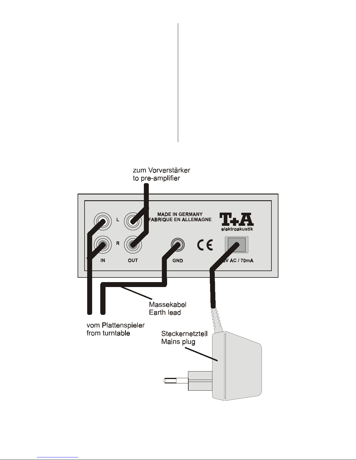
Hinweise zum Anschluss
• Stecken Sie die Ausgangskabel des Plattenspielers in die
Eingangsbuchsen
'IN'
des Phonovorverstärkers.
• Verbinden Sie die Ausgangsbuchsen des Phonovorverstärkers
'OUT'
mit den Eingangsbuchsen des Vorver-
stärkers, z. B.
'AUX'
(!) Achten Si auf die richtige Zuordnung der Stereokanäle!
(!) Stecken Sie alle Stecker fest in die Buchsen ein. Lockere
Steckverbindungen können Brummen oder andere Störgeräusche verursachen!
• Zur Vermeidung von Brummeffekten wird das Massekabel des Plattenspielers unter die Masseschraube
'GND'
geklemmt.
• Das Kabel des Steckernetzteiles
SN1
wird gemäß Anschlussschema mit der entsprechenden Buchse des
PH 2000 verbunden.
Wenn das Steckernetzteil in eine Netzsteckdose (220 ...
230 V) eingesteckt wird, so leuchtet die Betriebsanzeige
an der Frontseite des Gerätes.
Da der Phonovorverstärker sehr wenig Strom aufnimmt,
bleibt er ständig mit dem Netz verbunden und braucht
nicht ausgeschaltet zu werden.
Wird das Gerät längere Zeit nicht benutzt, ist es vorteilhaft,
das Steckernetzteil aus der Netzsteckdose zu ziehen.
Notes on connecting the phono pre-amplifier
• Locate the turntable output cables and plug the
connectors into the input sockets marked
'IN'
on the
phono pre-amplifier.
• Locate the output sockets
'OUT'
on the phono preamplifier and connect them to the input sockets on the
pre-amplifier, e.g.
'AUX'
.
(!) Check that the stereo channels are correctly assigned!
(!) Push all plugs firmly into the sockets. Loose connections
can cause hum and other unwanted noises.
• Locate the earth lead attached to the turntable, and
clamp it under the head of the earth screw
'GND'
; this
avoids earth loop hum.
• Locate the cable
SN1
attached to the plug-type mains
PSU and connect it to the appropriate socket on the PH
2000, as shown in the wiring diagram.
When the mains PSU is connected to a mains wall
socket (220 … 230 V) the indicator lamp on the front of
the unit will light up.
The phono pre-amplifier draws a very small current, so it
can safely be left connected to the mains permanently; it
does not need to be switched off.
If the unit is not to be used for a long period, we
recommend that the plug-type mains PSU should be
disconnected from the mains wall socket.
Page 6
6
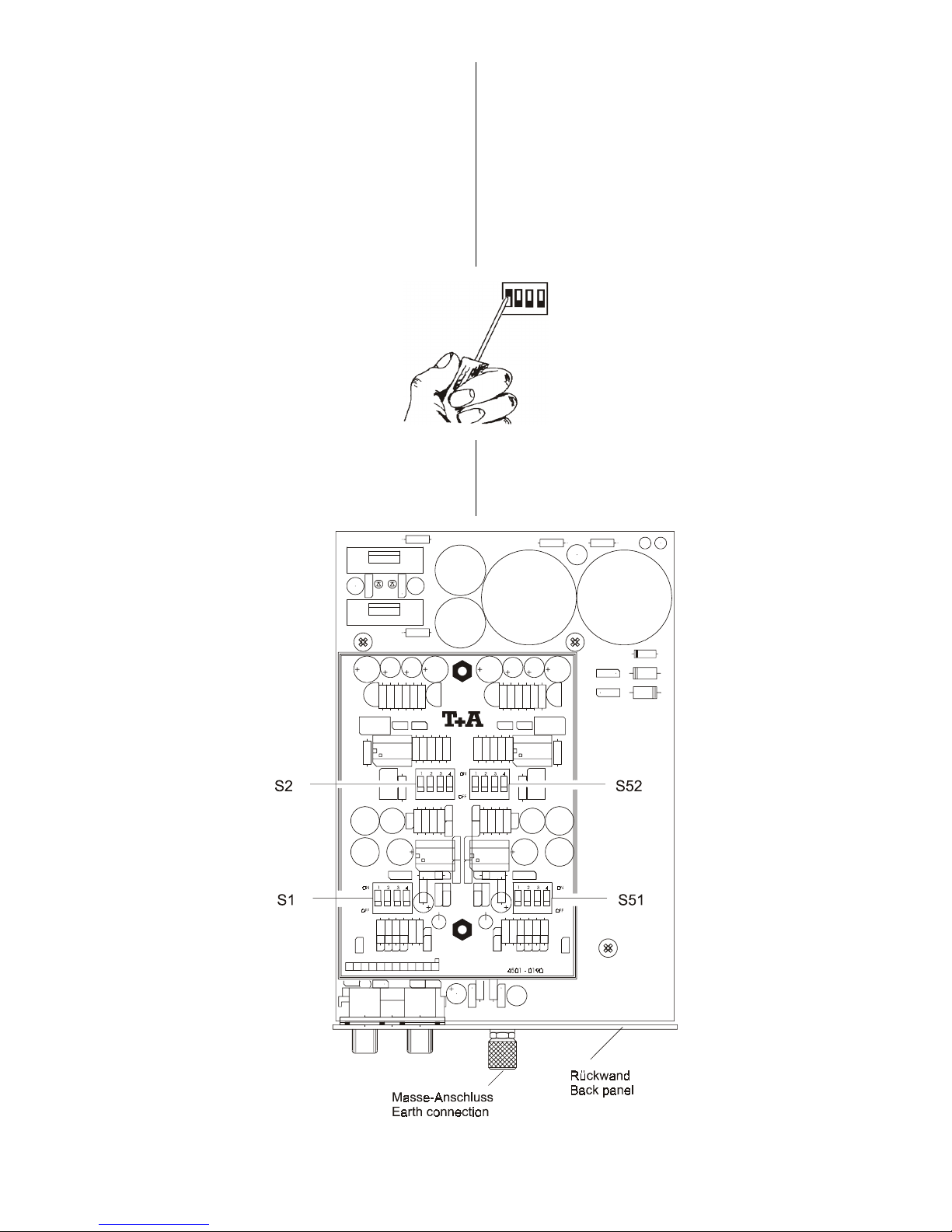
Die Codierschalter
Nach Lösen der vier Schrauben auf der Geräteunterseite
wird das Chassis vorsichtig nach hinten aus den Gehäuse
herausgezogen.
Nur bei MC-Modul:
Den Deckel des Phono-Moduls öffnen, so dass die
Codierschalter zugänglich werden.
Mit Hilfe eines kleinen Schraubendrehers können nun die
einzelnen Schalter in die gewünschte Position
'ON'
oder
'OFF'
geschoben werden.
The code switches
Undo the four screws on the underside of the unit and
carefully pull the chassis out of the case to the rear.
MC module only:
Open the cover of the phono module to provide access to the
code switches.
You can now move the individual switches to the desired
'ON'
or
'OFF'
position using a small screwdriver.
Die genaue Einstellung der Eingangsempfindlichkeit sowie
die perfekte Anpassung (Eingangsimpedanz bei MC-Modul
bzw. Eingangskapazität bei MM-Modul) erfolgt gemäß
Tabelle 1 und Tabelle 2.
Please refer to Tables 1 and 2 for details of the correct
settings for input sensitivity and matching (input impedance
for MC modules, input capacitance for MM modules).
Page 7
7
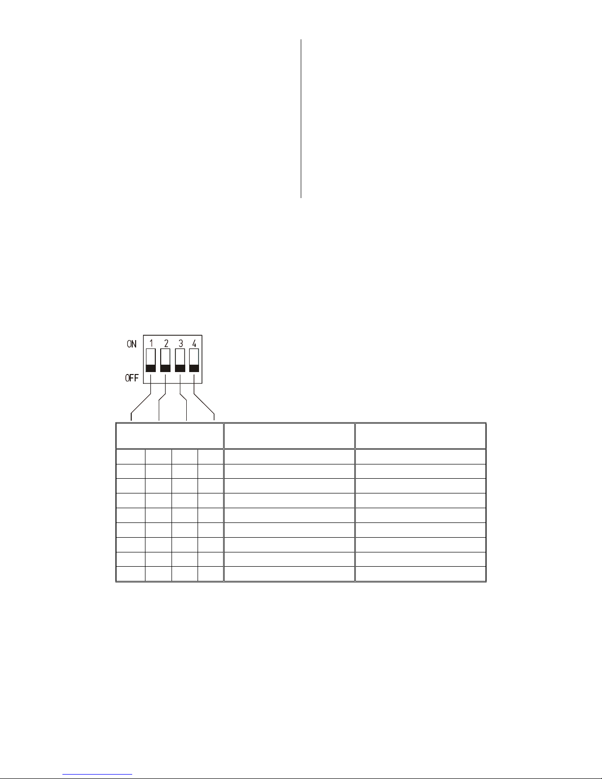
Einstellen der Eingangsempfindlichkeit
Mit den Codier-Schaltern
'S2/S52'
wird die gewünschte
Eingangsempfindlichkeit für den linken und rechten Kanal
gemäß Tabelle 1 eingestellt.
Die benötigten Daten entnehmen Sie den Herstellerangaben
des Tonabnehmersystems. Wählen Sie den Wert, der den
Herstellerangaben am nächsten liegt. Es müssen unbedingt
beide Kanäle gleich eingestellt werden!
Sollten Ihnen keine Herstellerangaben vorliegen, benutzen
Sie zunächst die Werkseinstellung
MC
: 250 μV
MM
: 2,0 mV
Hinweis:
1000 μV entspricht 1 mV
Setting the input sensitivity
The code switches
'S2/S52'
are used to set the desired input
sensitivity for the left-hand and right-hand channels.
The information required for this setting should be included in
the Specification provided by the pick-up cartridge
manufacturer. Select the value which is closest to the
manufacturer’s stated figure. Be sure to select the same
setting for both channels!
If you do not have the manufacturer’s Specification, start with
the factory default settings:
MC
: 250 μV
MM
: 2,0 mV
Note:
1000 μV = 1 mV
Schalterstellung
Switch position
Eingangsempfindlichkeit
Input sensitivity
Eingangsempfindlichkeit (MM)
Input sensitivity (MM)
OFF OFF OFF OFF > 2000 μV 6mV ... 10,0mV
OFF OFF OFF
ON
1200 μV ... 2000 μV 3,5mV ... 6,0 mV
OFF OFF
ON
OFF 800 μV ... 1200 μV 2,5mV ... 3,5 mV
OFF OFF
ON ON
600 μV ... 800 μV
OFF
ON
OFF OFF 400 μV ... 600 μV 1,5mV ... 2,5mV
OFF
ON ON
OFF 300 μV ... 400 μV
ON
OFF OFF OFF 200 μV ... 300 μV 1mV ... 1,5mV
ON ON
OFF OFF 160 μV ... 200 μV
ON ON ON ON
100 μV ... 160 μV
Tabelle / Table 1
Page 8
8
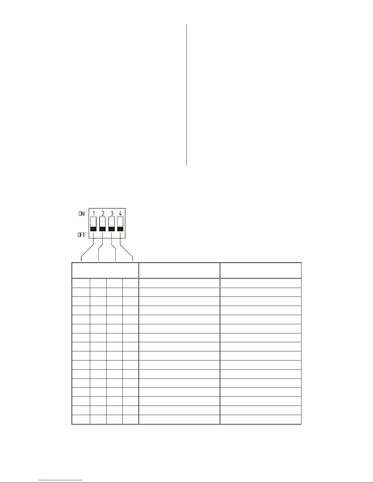
Eingangsimpedanz (MC) bzw.
Eingangskapazität (MM)
Die Einstellung erfolgt durch die Codier-Schalter
'S1/S51'
für
den linken und rechten Kanal. Die benötigten Daten
entnehmen Sie den Herstellerangaben des
Tonabnehmersystems. Beachten Sie bitte, dass auch das
Phono-Anschlusskabel eine Kapazität darstellt, je nach
Hersteller zwischen 50 pF und 200 pF.
Wählen Sie den Wert, der den Herstellerangaben am
nächsten liegen. Es müssen unbedingt beide Kanäle gleich
eingestellt werden. Sollten Ihnen keine Herstellerangaben
vorliegen, benutzen Sie zunächst die Werkseinstellung
MC
: 100 Ω
MM
: 120 pF
Die Einstellung ist damit abgeschlossen. Den Deckel des
Abschirmgehäuses auflegen, das Chassis vorsichtig in das
Gehäuse zurückschieben und an alter Position mit den vier
Schrauben von unten wieder befestigen.
Input impedance (MC) and
input capacitance (MM)
The code switches
'S1/S51'
are used to set these values for
the left-hand and right-hand channels. The information
required for this setting should be included in the
Specification provided by the pick-up cartridge manufacturer.
Please note that the phono cable also adds its own
capacitance; this lies in the range 50 pF to 200 pF, according
to manufacturer.
Select the value which is closest to the manufacturer’s stated
figure. Be sure to select the same setting for both channels!
If you do not have the manufacturer’s Specification, start with
the factory default settings:
MC
: 100 Ω
MM
: 120 pF
This completes the settings. Place the cover of the shield
housing in position, then carefully slide the chassis back into
the case in its original position. Fit and tighten the four
screws from the underside.
Schalterstellung
Switch position
Eingangsimpedanz (MC)
Input impedance (MC)
Eingangskapazität (MM)
Input capacitance (MM)
OFF OFF OFF OFF 450 Ω ... 650 Ω ... 120 pF
OFF OFF OFF
ON
200 Ω ... 449 Ω 121 pF ... 140 pF
OFF OFF
ON
OFF 130 Ω ... 199 Ω 141 pF ... 160 pF
OFF OFF
ON ON
85 Ω ... 129 Ω 161 pF ... 190 pF
OFF
ON
OFF OFF 50 Ω ... 84 Ω 191 pF ... 220 pF
OFF
ON
OFF
ON
221 pF ... 240 pF
OFF
ON ON
OFF 30 Ω ... 49 Ω 241 pF ... 260 pF
OFF
ON ON ON
261 pF ... 290 pF
ON
OFF OFF OFF 20 Ω ... 29 Ω 291 pF ... 340 pF
On
OFF OFF OFF 341 pF ... 360 pF
ON
OFF
ON
OFF 361 pF ... 380 pF
ON
OFF
ON ON
381 pF ... 400 pF
ON ON
OFF OFF 16 Ω ... 19 Ω 401 pF ... 440 pF
ON ON
OFF
ON
441 pF ... 460 pF
ON ON ON
OFF 461 pF ... 480 pF
ON ON ON ON
... 15 Ω 481 pF ... 500 pF
Tabelle / Table 2
Page 9

9
Technische Daten / Specification
Eingangsempfindlichkeit
(für Ausgangspegel 250 mV
eff
)
:
Input sensitivity
(for 250 mVeff output level)
:
60 μV ... 1000 μV (MC) /
1 mV ... 5 mV (MM)
*)
Eingangsimpedanz (MC):
Input impedance (MC):
5 Ω ... 650 Ω
*)
Eingangskapazität (MM):
Input capacitance (MM):
100 pF ... 500 pF
*)
Frequenzgang
(nach RIAA)
:
Frequency response
(RIAA)
:
+ / - 0,05 dB
Subsonicfilter:
Sub-sonic filter:
2.Ordnung 10 Hz (fest)
2
nd
order, 10 Hz (fixed)
Fremdspannungs-Abstand:
Signal : noise ratio (unweighted):
79 dB (MC) / 83 dB (MM)
Geräuschspannungs-Abstand:
Signal : noise ratio (A-weighted):
82 dB (MC) / 87 dB (MM)
Klirrfaktor:
Total harmonic distortion:
< 0,002 %
Intermodulation:
Intermodulation:
< 0,001 %
Kanaltrennung:
Channel separation:
> 90 dB
Leistungsaufnahme:
Power consumption:
1,5 VA
*)
durch Codierschalter veränderbar / can be changed using code switches
Technische Änderungen vorbehalten. / We reserve the right to alter specifications.
Page 10

elektroakustik GmbH & Co. KG
Herford * Deutschland * Germany
 Loading...