

Page 1

Software Version V 1.4 Bestell Nummer / Order No. 9103-0435 UK
INSTALLATION
K8
Page 2

2
Page 3

3
Contents
Connections, using the system for the first time
Basic settings of the K8 ........................................................................................................ 6
• System settings (System configuration menu) ........................................................... 6
• Setup-Menu (Settings), BluRay disc player settings ................................................. 18
Network Configuration ......................................................................................................... 29
The vTuner Premium Service .............................................................................................. 32
Connections ......................................................................................................................... 34
Listening zones, sound in adjacent rooms ........................................................................... 41
Special operation modes ..................................................................................................... 42
FD 100 Radio Remote Control ............................................................................................. 44
Installation and wiring .......................................................................................................... 46
Safety notes ......................................................................................................................... 48
FCC Information to the user ................................................................................................. 50
Miscellaneous
Trouble shooting .................................................................................................................. 50
Glossary ............................................................................................................................... 55
Network Terminology ........................................................................................................... 56
Supported Audio/Video files ................................................................................................. 59
Notes on Energy Saving ...................................................................................................... 60
Appendix
Wiring diagram ..................................................................................................................... 62
Specification ......................................................................................................................... 68
About these instructions
The section entitled ‘Installation’ describes all those controls and settings which are not often required, and are
generally only needed when you are setting up and using the system for the first time. This section also contains the
network settings for the K8 which are required when you first use the system.
These ‘Operating Instructions’ describe all the controls and functions of the K8 which are used frequently.
Symbols used in these instructions
Caution!
Text passages marked with this symbol contain important information which must be observe
d if the
machine is to operate safely and without problems.
This symbol marks text passages which provide supplementary notes and background information; they
are intended to help the user understand how to get the best out of the machine.
Page 4

4
Welcome.
We are delighted that you have decided to purchase a product. With your new K8 you have acquired a top-quality
piece of equipment which caters for the latest developments in the field of high-resolution HD surround sound and HD
video formats, without neglecting the requirements of the audiophile music lover.
This system represents our very best efforts at designing practical electronic equipment incorporating solid quality, userfriendly operation and a specification and performance which leaves nothing to be desired.
All these factors contribute to a piece of equipment which will satisfy your highest demands and your most searching
requirements for a period of many years. All the components we use meet the German and European safety norms and
standards which are currently valid. All the materials we use are subject to painstaking quality monitoring.
Our robust all-metal cases exclude any possibility of external sources of interference affecting the quality of reproduction.
From the opposite point of view our products’ electro-magnetic radiation (electro-smog) is reduced to an absolute
minimum by the outstandingly effective screening provided by the metal case.
All sub-assemblies and mains sections are designed to be extremely efficient. A European EUP directive will come into
force in future, relating to energy efficiency and the avoidance of greenhouse gases which are harmful to the climate; the
directive’s requirements will be very stringent, but our equipment satisfies them in full even today.
Our range of accessories includes high-quality cables and connectors.
We would like to take this opportunity to thank you for the faith you have shown in our company by purchasing this
product, and wish you many hours of enjoyment and sheer listening pleasure with your K8.
elektroakustik GmbH & Co KG
IMPORTANT! CAUTION!
This device contains a laser diode classed as higher than 1. To ensure constant safe operation, it is essential not to
remove any covers, nor to attempt to access the interior of the machine in any way.
All maintenance work should be entrusted to qualified Customer Service staff.
The following warning labels are attached to the device:
On the back panel of the case
CLASS 1
LASER PRODUCT
On the internal shielding cover of the disc mechanism
CAUTION:
VISIBLE AND INVISIBLE LASER RADIATION WHEN OPEN.
AVOID EXPOSURE TO BEAM
VORSICHT:
SICHTBARE UND UNSICHTBARE LASERSTRAHLUNG,
WENN ABDECKUNG GEÖFFNET NICHT DEM STRAHL AUSSETZEN
ATTENTION:
RAYONNEMENT LASER VISIBLE ET INVISIBLE EN CAS
D'OUVERTURE EXPOSITION DANGEREUSE AU FAISCEAU
DANGER:
VISIBLE AND INVISIBLE LASER RADIATION WHEN OPEN.
AVOID DIRECT EXPOSURE TO BEAM
Page 5
5
Manufactured under license from Dolby Laboratories. Dolby, Pro Logic, and the double-D symbol are
trademarks of Dolby Laboratories.
Manufactured under license under U.S. Patent #’s: 5,451,942; 5,956,674; 5,974,380; 5,978,762;
6,226,616; 6,487,535; 7,003467 & other U.S. and worldwide patents issued & pending. DTS, The
Symbol, a
nd Neo:6 are registered trademarks, & DTS Digital Surround, DTS 96/24 and the DTS logos
are trademarks of DTS, Inc. Product includes software, © DTS, Inc. All Rights Reserved.
Manufactured under license under U.S. Patent #’s: 5,451,942; 5,956,674; 5,974
,380; 5,978,762;
6,226,616; 6,487,535; 7,212,872; 7,333,929; 7,392,195; 7,272,567 & other U.S. and worldwide patents
issued & pending. DTS and the Symbol are registered trademarks, &DTS-HD, DTS-
HD Master Audio,
and the DTS logos are trademarks of DTS, Inc.
Product includes software, © DTS, Inc. All Rights
Reserved.
"iPod is a trademark of Apple Inc., registered in the U.S. and other countries."
"Made for iPod“ means that an electronic acce
ssory has been designed to connect specifically to iPod
and has been certified by the developer to meet Apple performance standards.
Apple is not responsible
for the operation of this device or its compliance with safety and regulatory
standards.
All
the components we use meet the European safety norms and standards which are currently valid.
The operation instructions, the connection guidance and the safety notes are for your own good -
please
read them carefully and observe them at all times.
This product complies with the Low Voltage Directive (73/23/EEC), EMV Directives (89/336/EEC, 92/31/EEC) and CE
Marking Directive (93/68/EEC).
About these instructions
The K8 amplifier with its seven output stages is extremely versatile: if all the output stages are not required for the
surround system in the main room, they can be used to provide sound in up to three additional rooms or listening zones
in the main room. It is possible to adjust the volume separately in the adjacent rooms or listening zones, or in parallel
with the main room.
All the controls and functions of the K8 which are frequently used are described in the first section of these operating
instructions.
The second part - 'Basic settings, Installation, Using the system for the first time' covers connections and settings
which are very seldom required; they are generally required only when the machine is set up and used for the first time.
Here you will also find a detailed description of the network settings required for connecting the K8 to your home
network.
For newcomers to networks we have prepared explanations of some of the important terms used in this technology and
other background information in the Chapter 'Network Terminology'.
Page 6
6
Basic settings of the K8
System settings (System configuration menu)
The System Configuration menu is used to enter general basic settings for the device. This menu is described in detail in
the following Chapter.
Calling up and operating
the menu
•
Briefly press the button on the front panel or on the remote control
handset to call up the menu.
•
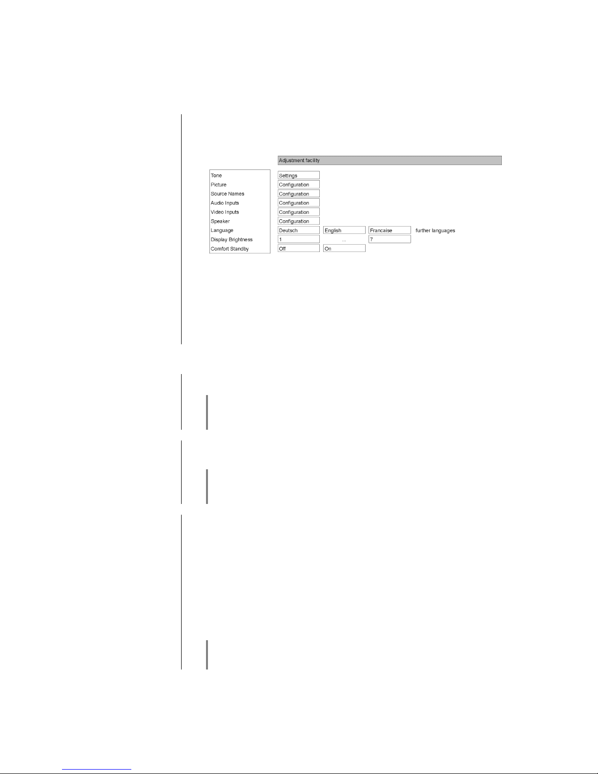
When you open the menu, the following Select points appear on the screen:
•
Use the / buttons to select a point in the menu.
•
If you wish to change a selected menu point, first press the button,
and then use the / buttons to alter it.
•
After making the change, press the button again to accept the new
setting.
•
You can press the button at any time to interrupt the process; the
change is then abandoned.
•
Press the button again to leave the menu.
Tone controls
menu point
Calls up the tone settings menu (Tone menu).
The tone control menu can also be called up directly using the button
on the remote control handset.
For details see the chapter 'Tone settings (Tone menu)'
Picture settings
menu point
This menu point calls up the picture settings menu
(only displayed when a video source is selected).
This menu can also be called up directly using the button on the FM100
hand-set.
For details see the chapter 'Picture settings (Video settings)'
Source name
s
menu point
At this menu point you can activate and disable external sources, and assign a
plain text name to each source; this name then appears in the screen displays.
When you call up this menu point using the button, a list of all the
external sources of the K8 appears. Each source is followed by the assigned
name, or - if you have disabled the source concerned - the note 'disabled'.
If you want to activate / disable a source, or change the plain text name,
navigate to the appropriate line.
To activate a source, press the green button; pressing the red button disables
the source.
To change the plain text name, press the button once more. Change
the name as you wish, then press to confirm your choice. This action
stores the settings for the source.
When you call up Source Select using or the source button on
the front panel, any disabled sources are suppressed. This makes it easier to
select sources, and we recommend that you disable any sources not in use.
Page 7
7
Audio inputs
menu point
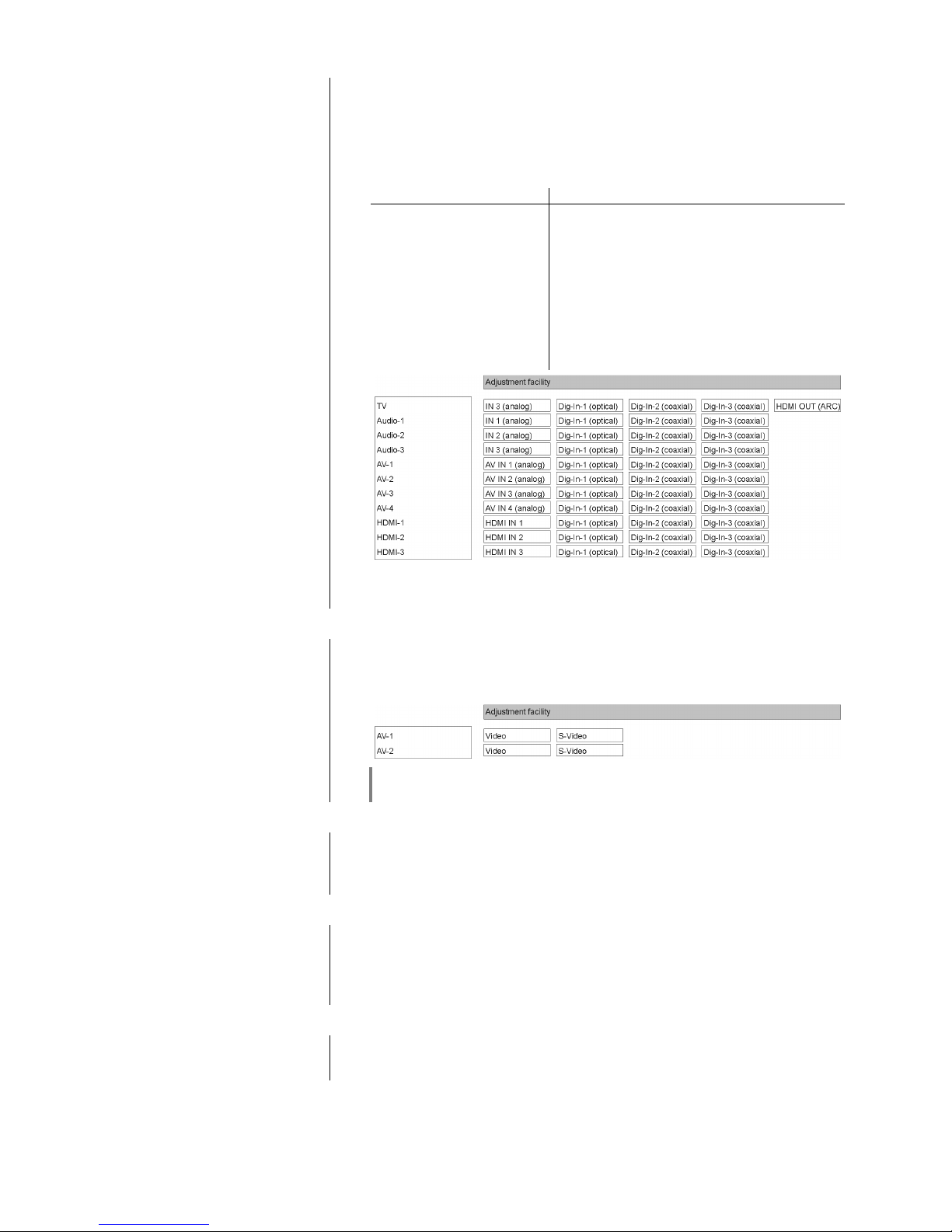
Some audio and video source devices feature digital electrical (co-axial) or
optical (TOSLINK) outputs instead of analogue sound outputs. If you wish to
use the K8 with such source devices, you can assign an optical or electrical
digital input to the external audio and video sources instead of the analogue
sound input. In this case the K8 accepts and processes the digital stereo or
surround signal from the source, instead of the analogue signal.
Back panel socket Menu display
HDMI OUT TV / user-selected plain text name
IN 1 Audio 1 / user-selected plain text name
IN 2 Audio 2 / user-selected plain text name
IN 3 Audio 3 / user-selected plain text name
AV IN 1 AV-1 / user-selected plain text name
AV IN 2 AV-2 / user-selected plain text name
AV IN 3 AV-3 / user-selected plain text name
AV IN 4 AV-4 / user-selected plain text name
HDMI IN 1 HDMI-1 / user-selected plain text name
HDMI IN 2 HDMI-2 / user-selected plain text name
HDMI IN 3 HDMI-3 / user-selected plain text name
On the left of the picture of the menu can be seen a list of the alternative co-
axial and optical inputs of the K8 (DIG-1, DIG-2, DIG-3). Each of these alternative inputs can be assigned to an audio or AV input.
Video inputs
menu point
The option of Video sockets (Composite Video) or S-Video socket is available
for the AV inputs AV IN1 and AV IN2.
You can select the appropriate input socket at this menu point, according to the
specification of the source device to be connected to the system.
If your device features S-Video outputs, we recommend that you use S-Video,
as this provides better picture quality.
Loudspeaker
menu point
This menu point is used to call up the Loudspeaker Configuration menu (see
following Chapter), where you can enter the basic settings for your surround
loudspeaker set.
Language
menu point
In this menu point you define the language to be used for the displays on the
screen of the front panel of the K8.
The language used for data transferred to the machine, e.g. from an iPod or
other Internet radio station, is determined by the supplying device or the radio
station; you cannot define the language on the K8.
Brightness
menu point
(screen brightness)
At this point you can adjust the brightness of the integral screen to suit your per-
sonal preference for normal use; seven levels are available.
Page 8

8
Comfort Standby
(Stand-by mode)
menu point
The K8 features two stand-by modes: ECO Standby with reduced stand-by
current drain, and Comfort Standby with additional functions, but slightly higher
current drain. You can select your preferred stand-by mode in this menu point:
Off (ECO Standby):
Active functions in ECO Standby mode: can be switched on by remote control,
alarm timer
On (Comfort-Standby):
The following expanded functions are available: LAN switch (see Chapter
Glossary), Clock display, iPod battery charge function.
For information on energy-saving operation, and accurate information on
current drain in the various operating modes, please refer to the Chapter
entitled 'Economical use of energy' and the Specification in the Appendix
If you wish the network function of the LAN, HDMI and UPLINK sockets to be
maintained even when the K8 is on stand-by (i.e. in order to keep the system’s
games console or TV set constantly connected to the Internet), you must select
Standby mode 'On (Comfort Standby)'.
In order to fulfil the European regulations for stand-by current drain, the default
setting is “ECO Standby”.
Page 9
9
Loudspeaker configuration
menu
(Loudspeaker menu)
The Loudspeaker menu is used to allocate the output signals to the loud-
speakers present in your system in the optimum manner. At the same time the
speakers can also be adjusted accurately to match the acoustic and spatial
characteristics of your listening room.
The K8 features automatic loudspeaker detection, which enables it to detect
which loudspeakers are connected every time it is switched on.
Certain points in the Tone menu only appear if the associated loudspeakers are
actually connected to the system and switched on. If the speakers concerned
are not present, then the set-up points affecting them are not displayed. This
greatly simplifies the procedure by restricting the facilities to the speakers which
are actually present.
If some menu points are not displayed, even though the associated loudspeakers are correctly connected, please refer to the notes in the Chapter entitled ‘Trouble shooting’.
Loudspeaker
sub-menu
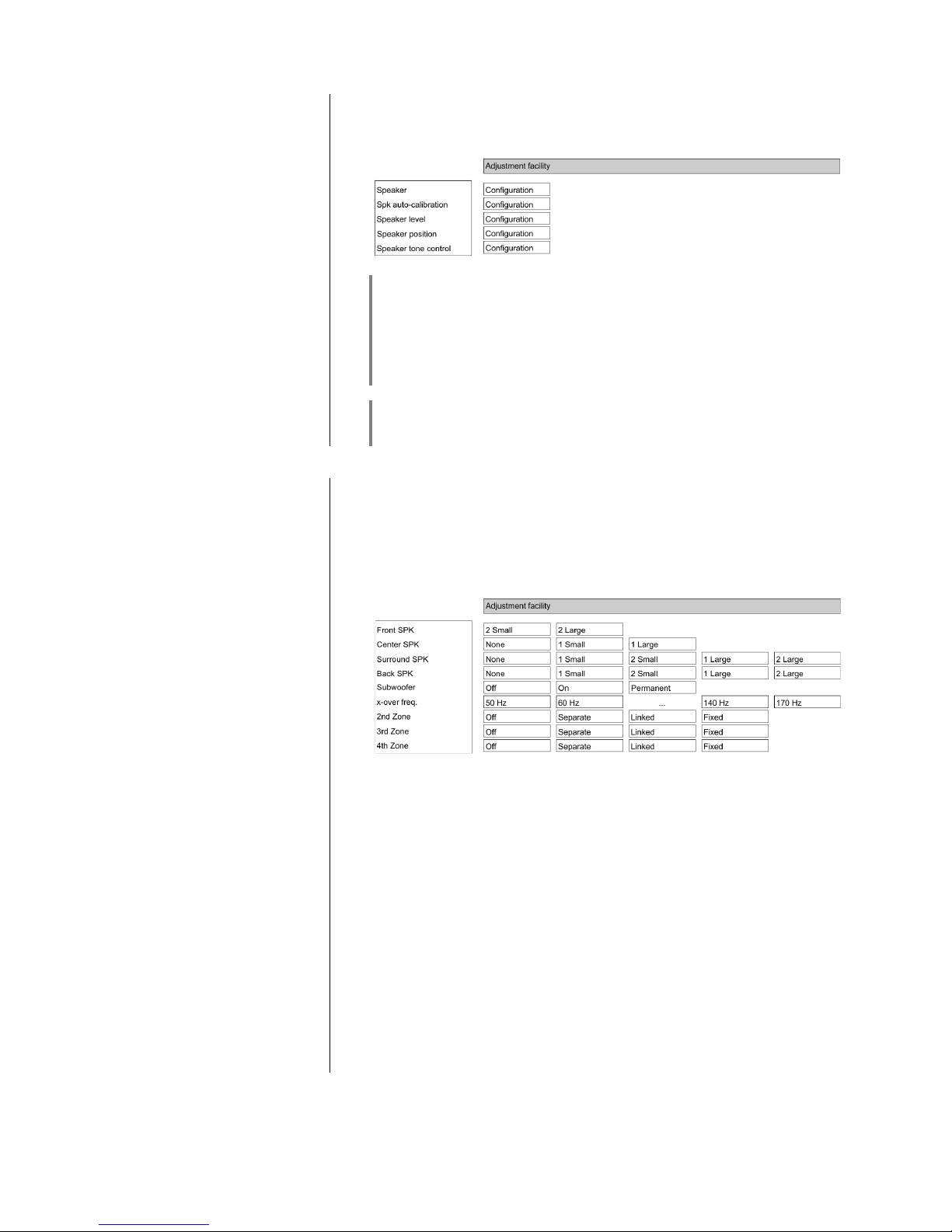
Activating this menu point takes you to a menu where you can define the size of
the loudspeakers and the mode of operation of the sub-woofer. You can also
set the cross-over frequency for satellite / sub-woofer systems at this point.
This sub-menu is also used to select whether the surround channels of 5.1
input signals are to be reproduced only by the surround speakers, or the rear
speakers, or both.
In the 'Loudspeaker menu' the first procedure is to allocate the output signals
correctly to the various loudspeakers present in the system.
To ensure that no sound information is lost if your system does not encompass
all the possible loudspeakers (Centre, Rear and sub-woofer), it is essential to
mark the missing components as “None” in the ‘Loudspeaker menu’. The
corresponding sound signal is then mixed down onto the channels which are
actually present (Downmix).
Front LS:
At this point you can define the size and bass response of the primary loudspeakers situated at front left and right. The following options are available:
2 small for small speakers whose bass response by their nature is not
optimum. The low-frequency bass signals (below the set
cross-over frequency) of the main channels are mixed onto
the sub-woofer, if it is present in the system.
2 large for larger speakers. The whole frequency range is reproduced
via the main channels without restriction.
Page 10

10
Centre LS:
At this point you can define the size and bass response of the Centre loudspeaker. The following options are available:
Small(r) if no Centre speaker is present. The Centre channel is mixed
down onto the left and right main loudspeakers.
1 small for small Centre speakers. The low-frequency bass signals of
the Centre channel (below the set cross-over frequency) are
mixed down onto other suitable loudspeakers and - if present
- the sub-woofer.
1 large if the Centre speaker is approximately the same size as the
main speakers. The whole frequency range is reproduced via
the Centre channel, without restriction.
If your system does not include a Centre speaker, it is important not to situate
the main loudspeakers too far from the television set; they should also be set up
in a symmetrical arrangement relative to the TV. If you neglect this, the
localisation of dialogue on the screen will be very poor.
Surround LS:
At this point you can define the size and bass response of the Surround loudspeakers.
Small(r) no Surround speakers present.
1 small one small Surround speaker present
2 small two small Surround speakers present
1 large one large full-range speaker present
2 large two large full-range speakers present
If you system does not include surround speakers, the surround channels are
mixed down onto the left and right main loudspeakers.
At the “Small” setting the bass manager mixes the low-frequency bass signals
of the surround channels (below the set cross-over frequency) onto the front
loudspeakers and - if present - the sub-woofer.
At the “Full” setting the whole frequency range is reproduced by the surround
speakers without restriction. In this case the speakers must be capable of
reproducing low-frequency bass signals at full level.
Genuine surround sound is not possible without two surround speakers! A
single surround speaker located at the rear can provide a limited surround effect; it should be positioned centrally behind the listening point. In this case
select “1 small” or “1 full”, according to the size of the loudspeaker.
Page 11

11
Back LS:
At this point you can define the size and bass response of the rear speakers.
The following settings are possible for systems with one (6.1 mode) and two
(7.1 mode) rear speakers:
Off no rear speakers present
1 small 1 small rear speaker
2 small 2 small rear speakers
1 full 1 large rear speaker
2 full 2 large rear speakers
If your system does not include rear speakers, the rear channels - if present are mixed down onto the left and right surround speakers; otherwise onto the
front speakers.
If you select the ‘none’ setting in the menu point 'Surround loudspeakers', the
rear speakers are automatically switched off.
To avoid the risk of accidentally setting senseless speaker arrangements, the
system does not allow you to select all combinations.
Page 12

12
Subwoofer:
In this menu point you can define whether your loudspeaker system includes a
sub-woofer, and which signals it is required to reproduce. The following options
are available:
On Recommended setting for sub-woofer / satellite systems
The signals from the bass effect channel (LFE) and all other
low-frequency bass signals (below the set cross-over
frequency), which are not reproduced by the full-range
loudspeakers, are assigned to the sub-woofer. In this mode it
may occur that the sub-woofer has no signal to reproduce in
certain surround modes, or in the case of multi-channel input
signals without an LFE channel.
If you decide to use the bass manager, you should switch off
the low-pass filter on the sub-woofer, as the bass manager
carries out the filtering.
Off This setting should only be selected if at least the main loud-
speakers are of the full-range type.
Your system does not include a sub-woofer. The signals of
the bass effect channel (LFE) and all other low-frequency
bass signals (below the set cross-over frequency) are assigned to the main loudspeakers.
Permanent recommended setting for full-range loudspeakers and sub-
woofer. If a sub-woofer is present and you wish it to operate
constantly. In addition to bass management the signals of all
channels are mixed together and reproduced by the subwoofer.
If the sub-woofer is switched on in the 'Loudspeaker menu', its level can be
altered within the range -20 (dB) und +10 (dB) in the ‘Loudspeaker level’ menu.
This enables you to match the volume of the sub-woofer to the volume of the
other channels.
Cross
-
over frequency:
At this point you can select the lower limit frequency for satellite loudspeakers.
For all loudspeakers whose size is ranked as ‘satellite’, the bass manager
mixes the bass signals (below the frequency set at this point) onto the subwoofer and other loudspeakers with a suitable frequency range.
The following values (Hz) can be set:
50 60 70 80 90 110 140 170
Page 13

13
Zone 2:
If your system does not include rear loudspeakers, the output stages for the
rear channels can be used to provide sound in an adjacent room (listening zone
2). In this menu point you can enter the settings required for listening zone 2:
Off
Zone 2 switched off.
Select this setting if listening zone 2 is not in use.
At this setting the rear channel output stages of the K8 are switched off.
This saves energy, and the K8 develops less heat in use.
Separate
Zone 2 switched on – separate volume control.
Volume is controlled separately from that of the main loudspeakers.
This setting should be selected if the loudspeakers in zone 2 are set up in a
separate room, and their volume is controlled using their own remote control
handset. This arrangement requires an E2000 remote control receiver for
the adjacent room.
Linked
Zone 2 switched on – volume control in parallel with main room.
Volume is controlled in parallel with that of the main loudspeakers. This is a
sensible setting if the speakers in zone 2 provide sound in a listening zone
which forms a unit with the main space.
Fixed
Zone 2 switched on – fixed level.
Volume control for zone 2 is disabled; a fixed volume level is set.
This option can be used if the level is controlled by a volume control
installed locally in the adjacent room, or if active loudspeakers or audio
radio transmission systems with their own volume control are operated from
the zone 2 pre-amplifier output.
This menu point only appears if no rear loudspeakers are present, and you
have selected the “OFF” setting under the menu point “Rear loudspeakers”.
Zone 3:
If no surround loudspeakers are present in your system, the output stages for
the surround channels can be used to provide sound in an adjacent room (listening zone 3). In this menu point you can enter the settings required for listening zone 3.
The set-up options (OFF / Separate / Linked / Fixed) are the same as those
described above for zone 2.
This menu point only appears if no surround loudspeakers are present, and you
have selected the “OFF” setting under the menu point “Surround loudspeakers”.
Zone 4
The K8 features a pre-amplifier output (Zone 4) which can be used to provide
sound in a listening zone using active loudspeakers or an audio radio transmission system. This listening zone is always available - i.e. even if you have
installed a full 7.1 channel surround system in the main room.
The set-up options (OFF / Separate / Linked / Fixed) for zone 4 are the same as
those described above for Zone 2.
Page 14

14
Spk auto
– calibration
sub-menu
With the Speaker automatic–calibration offers you an effective aid to
obtaining the correct level and sound settings for your surround system. If you
carry out the procedure outlined below, the K8 will automatically calibrate your
loudspeakers with the help of the measuring microphone supplied in the set;
under normal listening room conditions this process delivers excellent results.
If the result of the calibration process is to be correct, the following criteria need
to be satisfied:
The appropriate loudspeaker sizes should be selected in the ‘Loudspeaker’
menu point, and any speakers not actually present should be disabled.
Furthermore the correct speaker distances should be selected in the 'Speaker
position' menu point.
The measuring microphone should be set up in an unobstructed position close
to your preferred listening position (e.g. on the living room table, or the armrest
of an armchair), and there should be direct line-of-sight contact between the
microphone and each loudspeaker.
If you wish to use the automatic calibration system, please carry out the
following procedure:
• First connect the calibration microphone (supplied in the set) to the socket
on the underside of the machine, and set it up at the listening position.
• Call up the System menu by pressing the button.
• Now select the ‘Automatic calibration’ point in the ‘Loudspeaker
configuration’ menu. You will hear a hissing sound from the front left
loudspeaker.
• At this point you may be requested to increase or reduce the volume,
depending on the volume you have currently set on the K8. If this should
happen, adjust the volume using the / buttons until the
message ‘Press OK to continue’ appears. Now press the button.
• The K8 now starts the automatic calibration process. During the procedure
you will hear various test signals from your loudspeakers. It is important
that no loud noises should occur during the calibration period, as these
could falsify the results.
• The screen will inform you when the process is complete. If you wish to
save the calibration values, select ‘yes’ with the / buttons,
and confirm with the button.
If necessary, the stored settings (e.g. bass, treble, etc.) can be adjusted at any
time to suit your personal preference. Changes are made in the Loudspeaker
menu.
If the calibration process should be adversely affected by accidental noise or
disturbance, or if the system returns implausible results for any other reason,
the calibration process can simply be re-started at any time.
If the automatic calibration process delivers false results due to difficult acoustic
conditions in your listening room, you should vary the microphone position and /
or the volume setting in an attempt to obtain a better result.
If this is unsuccessful, i.e. if automatic calibration proves to be impossible, you
can still carry out the corrections required manually via the ‘Loudspeaker menu’.
Page 15

15
Level
sub-menu
The volume level of the individual channels must be matched very carefully to
ensure that the K8 delivers a balanced sound image.
The purpose of the 'level menu' is to calibrate the levels accurately for all
channels.
When you activate the 'level menu', you will hear a hissing sound lasting two
seconds from the left-hand main loudspeaker. The data input field is located
after the first menu point.
e.g. 'Front left: 00 '.
The hiss is now reproduced through the other channels in turn, in each case for
a period of about two seconds.
Output channels which are not in use (see 'Loudspeaker menu') are skipped.
While the hiss is generated on one channel, the associated data input field is
displayed on the screen. You can adjust the value within the range -20 to +10
using the Change buttons; any alteration you make is immediately audible.
After any correction to the volume, the same channel continues to generate the
hissing sound for a further two seconds, after which it moves on to the next
channel. The data input field position changes with it.
If you prefer to change the channels manually instead of automatically, you can
select the input position to be corrected using the Select buttons.
Your aim should be to set all the channels to the same perceived volume,
working as accurately as you can.
Since the hissing sound is not suitable for assessing bass volume, you should
use the 'Subwoofer' menu point in the 'Tone control settings (Tone menu)'
to adjust the volume of the sub-woofer channel.
The level for each channel is stored for surround reproduction, and applies to all
surround modes.
Page 16
16
Position
sub-menu
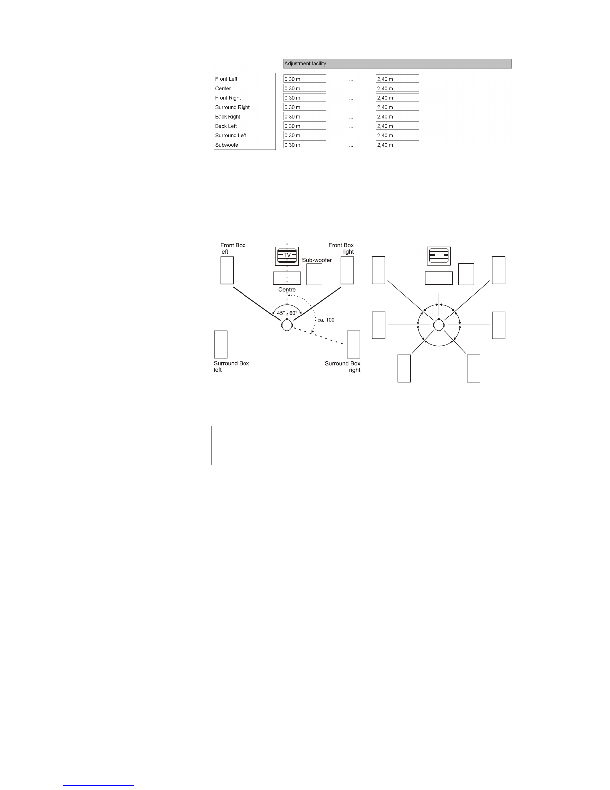
In the 'LS position menu' you can enter the actual distance of each loudspeaker
relative to the listening position (in 0.3 m increments).
This procedure is designed to compensate for timing discrepancies caused by
differing distances between the speakers and the listening position. The purpose of entering the speaker distances is to ensure that all the sound elements
reach the listener simultaneously and in correct phase. The correct setting of
the speaker distances is very important if you are aiming at optimum surround
effects.
5.1 Speaker set
7.1 Speaker set
30°
30°
60°
45°
90°
45°
60°
TV
Surround
left
Back speaker
left
Surround
right
Back speaker
right
Centre
Front Box
left
Front Box
right
Sub-woofer
Measure the distance between the listening position and the loudspeakers in
your room.
The maximum distance you can set between one loudspeaker and the listening
position is 12 m. For acoustic reasons greater distances are not recommended,
and for this reason the system cannot compensate for timing problems over
such distances.
As the diagram shows, you can use the Select buttons to move to the input
positions in turn; the order is stated below.
Enter the measured distance in increments of 0.3 m using the Change buttons.
Output channels not in use (see 'Loudspeaker menu') cannot be edited.
*
•
Main loudspeaker, front left (front left)
•
Centre loudspeaker, front centre (front centre)
•
Main loudspeaker, front right (front right)
•
Surround loudspeaker, right (Surnd right)
•
Rear loudspeaker, right (Rear right)
•
Rear loudspeaker, left (Rear left)
•
or rear loudspeaker, centre (Rear centre)
•
Surround loudspeaker, left (Surnd left)
•
Active sub-woofer (any position) (Sub)
Page 17
17
Tone
sub-menu
The
K8
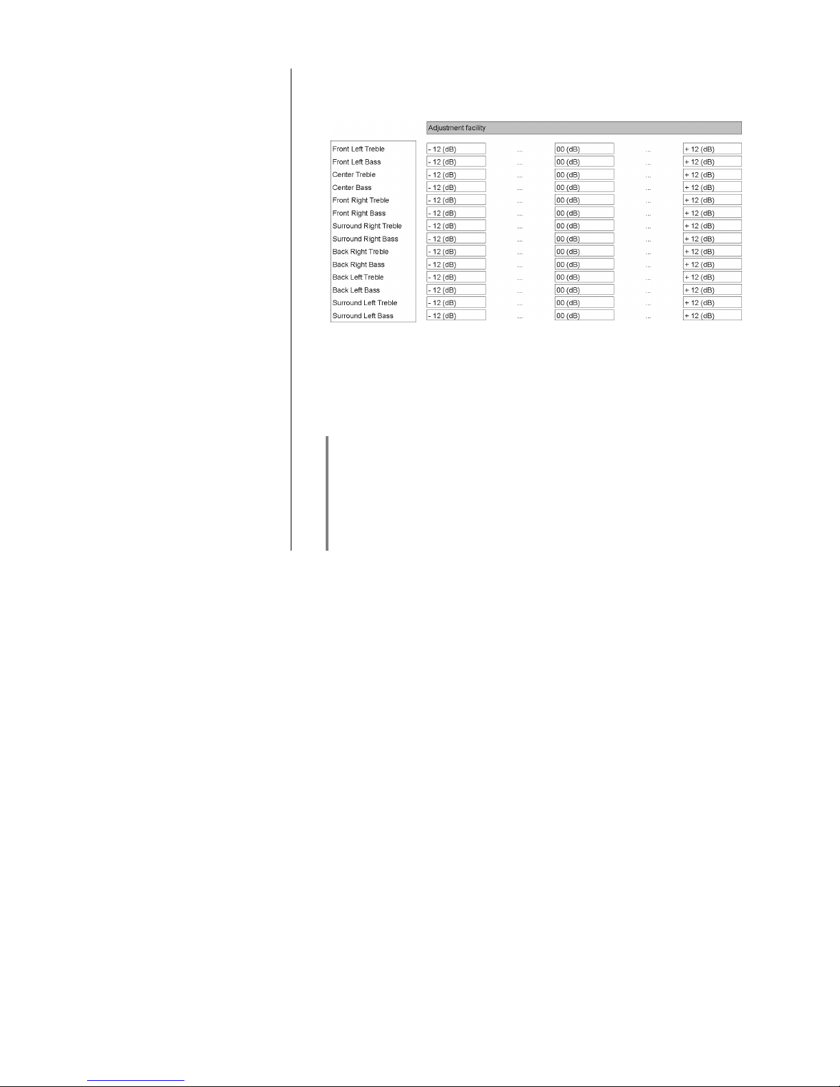
is equipped with active tone controls which are designed to compensate
for acoustic influences in the listening room, or unfavourable loudspeaker
locations.
First select a sound source which forms a suitable subject for adjusting the
tone. The sound source should be active on all channels, so that you can immediately hear the effect of any change in tone settings in as realistic a sound
image as possible.
Use the / buttons to select the menu point which you wish to
change. The value can now be altered using the Change buttons /
. Any alteration you make is immediately audible.
Tone adjustments are carried out separately for each of the output channels in
use, as this allows you to take into account different speaker locations and their
effects. Set values for treble (H) and bass (B) on all channels with the aim of
obtaining a finely balanced sound image.
Output channels not in use (see 'Loudspeaker menu') cannot be edited.
When you have completed the tone adjustments we recommend that you call
up the 'LS balance menu' again in order to check the level and balance of all
the channels, and correct them where necessary.
Page 18
18
Setup-Menu (Settings)
BluRay disc player settings
Opening and operating the
Settings menu
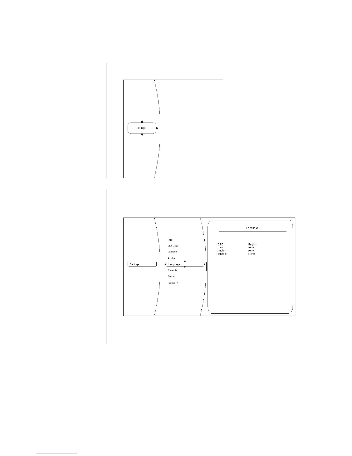
To open the Settings menu, stop playback.
Navigating to the Settings
menu point
Use the / buttons to select the Settings entry in the main menu.
You will now see the various sub-categories of the ‘Settings’ menu.
The selected category is highlighted, and the current settings in this category
are displayed:
In this example the Language category is selected, with the current settings dis-
played on the right.
You can select a different category (e.g. Parental control, System, ...) by
pressing / .
Page 19
19
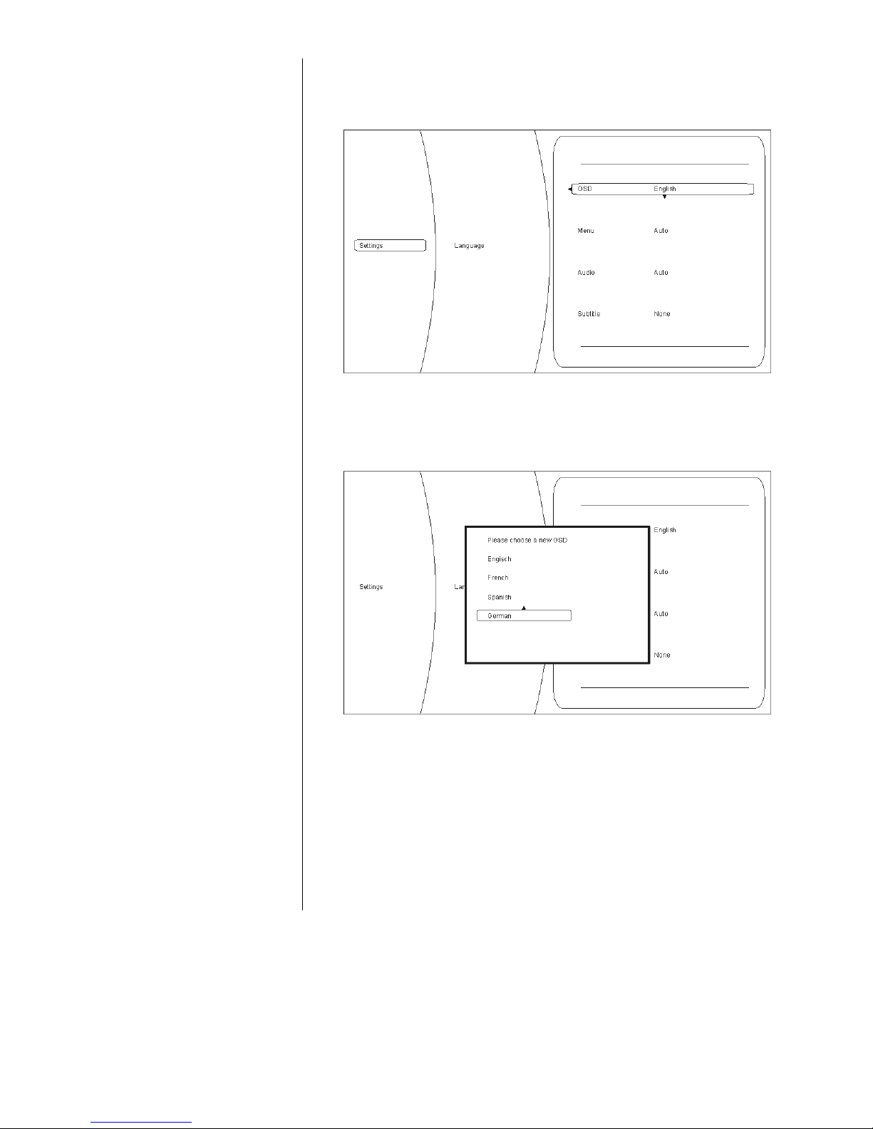
If you wish to change settings within the selected category, please press
() again.
The various options in the selected category are now displayed, and you can
select the setting you wish to alter using the / buttons.
In this example the option 'OSD' is selected, and 'Deutsch' (German) selected
as a possible setting.
If you wish to change the set value for the selected option, please press the
button. The available options are displayed in the Settings window.
You can now select a different setting (e.g. English) by pressing the /
button, followed by to accept and store the value.
The Setup menu contains the following categories:
• Display
• Language
• Parental control
• System
• Network
• Info
• BD-Live
These categories are described in greater detail in the following sections.
Page 20
20
Display category
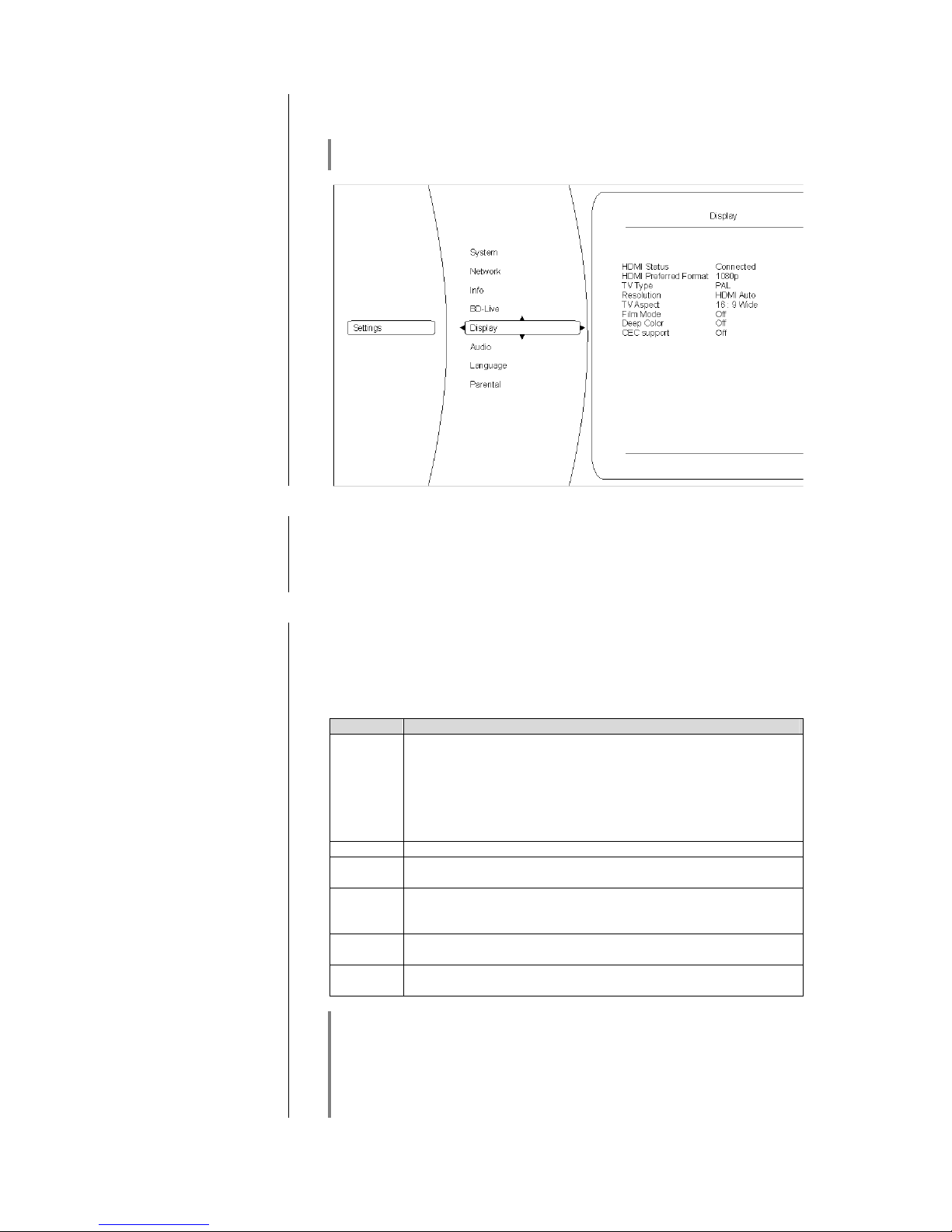
Please select the ‘Display’ category if you wish to set the optimum values for
the video outputs.
For optimum picture reproduction the K8’s internal video processor is bypassed. The Video menu cannot be called up when a disc is playing.
Overview
Colour system
Please set the video norm for your display device at this point.
NTSC: Video output at 60 Hz
PAL: Video output at 50 Hz
Incorrect settings may result in a jerky and incorrect display.
Resolution
At this point you should set the maximum resolution of the display device con-
nected to your system. For accurate information on the maximum resolution of
your display device please refer to the operating instructions supplied with the
unit.
The following resolutions are available:
Resolution
Display devices e
HDMI auto
The K8 automatically selects the optimum setting for the display
device connected to the system.
This is the recommended setting, which should always be
used if possible.
You can try out one of the other settings to see if it suits your
television, but only if the AUTO setting causes picture problems
with your TV.
1080p
Your display device is capable of full HDTV resolution (full HD).
1080i
The display device connected to the system is a high-definition
device (HDTV) which can only be used at 1080i resolution.
720p
The display device connected to the system is a high-definition
device (HDTV) such as an LCD or Plasma flat screen designated
‘HD-ready’.
576p
The display device connected to the system is a standard-definition
device which can also process progressive signals (SDTV).
576i
The display device connected to the system is a standard-definition
device (SDTV) for NTSC / PAL (e.g. conventional CRT television)
At any setting apart from AUTO you must also set the frame rate under “Colour
system” to match the disc in use.
PAL-DVD := PAL (50 Hz),
NTSC-DVD := NTSC (60 Hz)
BluRay := PAL or NTSC - according to the disc.
If you set the wrong frame rate, picture reproduction may be jerky.
Page 21
21
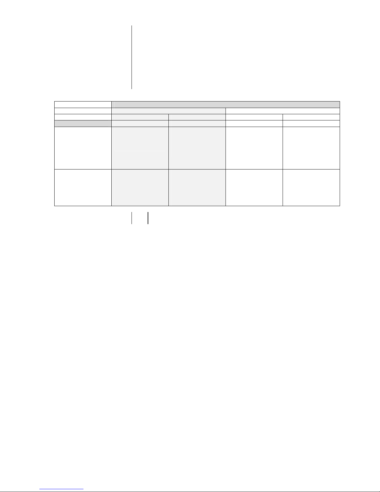
Picture aspect ratio
At this point you can determine the aspect ratio (16:9 / 4:3) of the display device
connected to your system.
The possible formats are:
• 16:9 widescreen
• 16:9 pillar-box
• 4:3 letterbox
• 4:3 pan & scan
Please select the appropriate setting from the table below:
Aspect ratio of the display device
16:9 4:3
16:9 widescreen 16:9 pillar-box 4:3 letterbox 4:3 pan & scan
Disc content
Film in widescreen
format (16:9)
The picture is
unchanged, and is
displayed filling the
screen
No effect –
the picture is
unchanged, and is
displayed filling the
screen
The picture is
unchanged, and
displayed full-width,
leaving horizontal
black bars above and
below the picture.
The picture is
unchanged, and
displayed full-height.
The right and left-
hand edges of the
picture are not
shown.
Film in 4:3 format The picture is
stretched
horizontally, and
displayed filling the
screen
The picture is
unchanged, and is
displayed centrally,
leaving vertical black
stripes on both sides
of the picture.
No effect –
the picture is
unchanged, and is
displayed filling the
screen.
No effect –
the picture is
unchanged, and is
displayed filling the
screen.
If you select the 16:9 setting when the display device connected to the system
is a 4:3 type, you may find that no picture is displayed at all.
Page 22

22
Film mode
This setting allows you to define whether your display device is capable of pro-
cessing film material directly at 24 frames per second.
Cinema films are usually recorded at a speed of 24 frames per second, and
many movies are also present on Blu-ray discs in this format. However, not all
display devices can process this format directly. It is important that you select
the correct setting for your display device:
On: Your display device is connected via HDMI, and can process film
material directly in the 24 fps (frames per second) format.
Off: Your display device cannot directly process film material in the 24 fps
(frames per second) format (e.g. conversion to 25 / 30 fps or 50 / 60
fps is required).
Selecting an incorrect setting may result in no picture on your display device!
The setting selected here is only effective:
-
if the resolution is set to 1080p / HDMI auto,
and
-
if the film material was recorded at 24 fps.
Deep Colour
This setting enables you to decide whether the picture to be transferred via the
HDMI output features expanded colour range (Deep Colour). The expanded
colour range allows for finer graduations in the colours to be displayed, which in
turn permits higher contrast values and better colour blends.
Please select the appropriate setting to suit your display device:
On: your display device is connected via HDMI and is capable of
processing Deep Colour.
Off: your display device cannot process Deep Colour.
CEC support
The CEC function enables your TV set’s remote control handset to operate the
basic functions of the K8’s disc mechanism.
If you wish to make use of this function, please ensure that the TV set
connected to the system supports the CEC function.
It is not possible to guarantee that the system works perfectly with all TV sets,
since manufacturers’ implementations of the CEC function vary.
If you find that the system malfunctions due to incompatibility problems, we
recommend that you switch this function off.
Leaving the category
When you have entered all the correct settings in the category, you can leave it
by pressing the button.
Page 23
23
Language category
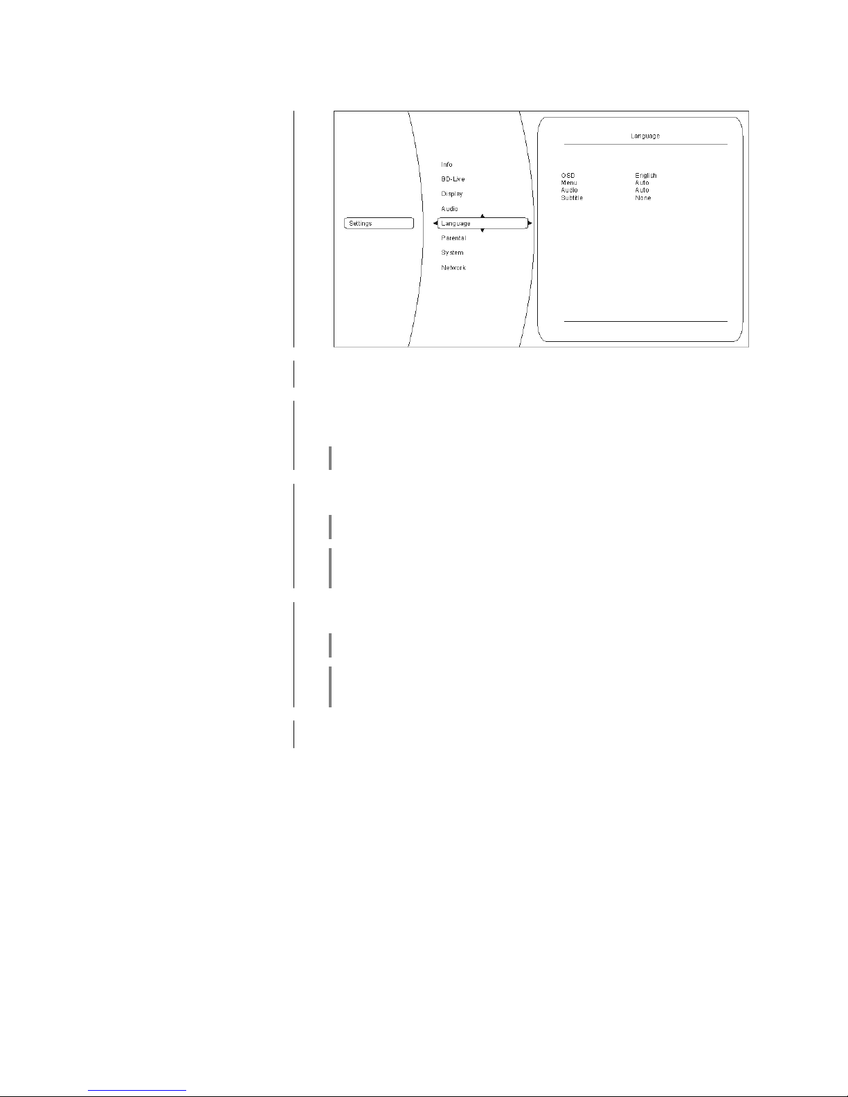
At this point you can select the language settings for the K8.
Overview
OSD
Here you can change the language used for the on-screen menus.
Please set your preferred language.
Menu
This setting defines the language in which the BluRay or DVD main menu is
displayed. If you select the 'AUTO' setting, the default language for the particular BluRay / DVD disc is used.
Please note that not all languages are present on every disc.
Audio
Setting for the film soundtrack. If you select the 'AUTO' setting, the default
language for the particular BluRay / DVD disc is used.
Please note that not all languages are present on every disc.
Some discs do not allow the language to be selected using the Setup menu of
the K8. In this case the language can only be changed using the main menu
present on the disc itself.
Sub-ti
tles
Setting for the language used for sub-titles.
If you set ‘OFF’, no sub-titles are shown.
Please note that not all languages are present on every disc.
Some discs do not allow the language to be selected using the Setup menu of
the K8. In this case the language can only be changed using the main menu
present on the disc itself.
Leaving the category
When you have entered all the correct settings in the category, you can leave it
by pressing the button.
Page 24
24
Parental control category
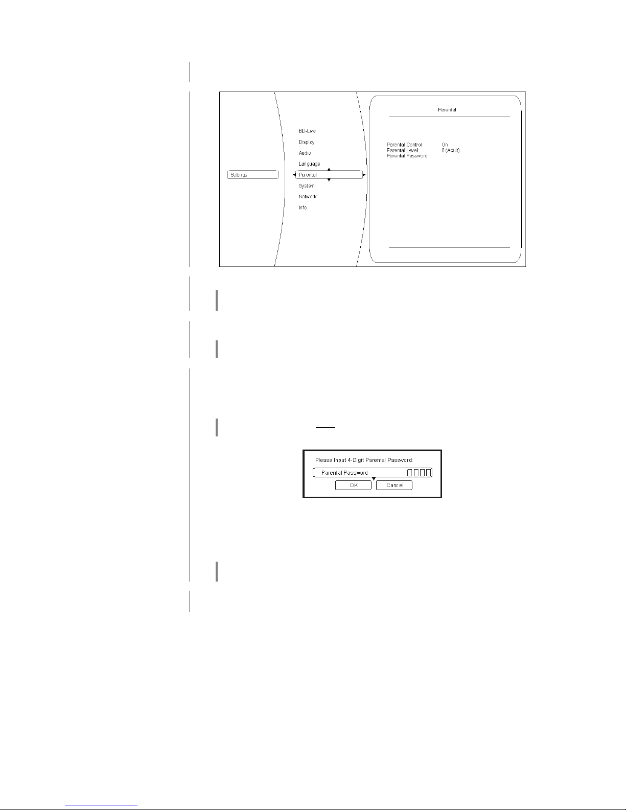
The parental control settings are designed to prevent children from watching
unsuitable discs. The setting determines which discs can be played.
Overview
Status
Here you can switch parental control on and off.
If you select the ‘On’ setting, changes in the ‘Parental control’ category can only
be made after entering the correct password.
Parental level
Here you can define the category of discs which can be played.
These settings are only effective if parental control is switched on!
Password
At this point you can define the password (code number) which is subsequently
required for changes to the parental control settings.
To enter a password, first select the category Parental control / Password, then
press the button to open password entry.
The default password is: 6666.
Please enter your password in the form of a four-digit number, press to
move to the OK field, then confirm your entry with .
From now on you must enter this number every time you wish to change the
parental control settings - assuming that you have selected ‘On’ in the Status
menu point!
If you forget the password, the only way you can reset the default number is to
load the ‘Reset settings’ in the ‘System’ category.
Leaving the category
When you have entered all the correct settings in the category, you can leave it
by pressing the button.
Page 25
25
System category
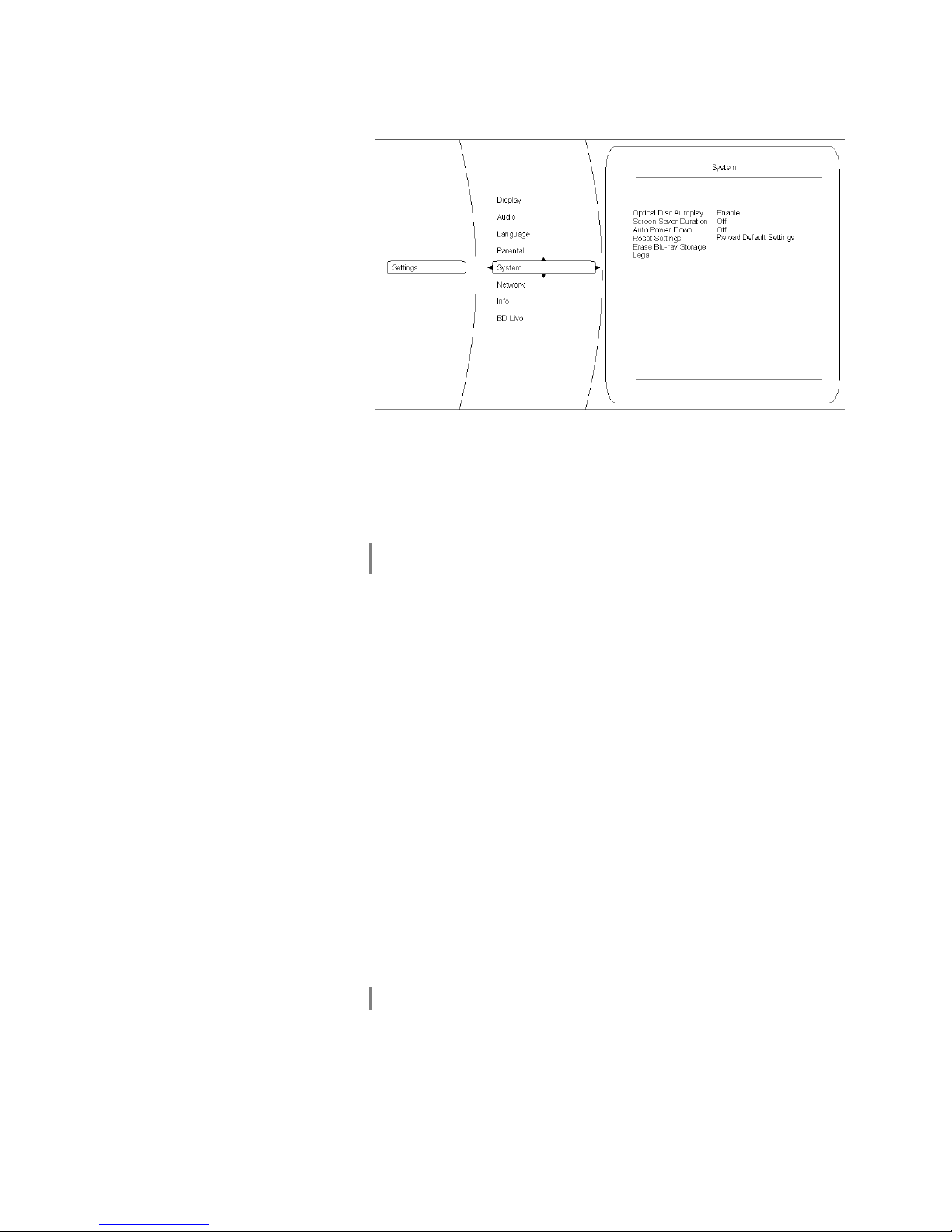
This category contains various system settings of the K8 such as options for
network access, USB, Play mode, ...:
Overview
Optical discs
At this point you can determine whether playback starts automatically when a
medium is inserted, i.e. without the need to press the Play button.
Activate: when you insert a disc, playback starts automatically without the
need to press / .
Disable: when you insert a disc, playback only starts after you press
/ .
The ‘Activate’ setting does not mean that the film starts immediately; the copyright warning and any previews present on the disc are not skipped!
Screen
-
saver
The
K8
features a screen-saver designed to prevent static images causing
damage (“screen-burn”) to the display device connected to the system.
The screen-saver is activated after a user-selectable time when playing music,
or if the main menu of a DVD / Blu-ray disc is displayed constantly; it simply
switches the screen dark.
Please use this option to define the time after which the screen-saver is triggered.
Possible settings are:
-
5 minutes
-
10 minutes
-
20 minutes
-
30 minutes
-
off
Autom
atic power
-
down
Please use this option to define the time after which the K8 disc mechanism
switches itself off.
Possible settings are:
-
30 minutes
-
45 minutes
-
60 minutes
-
off
Erase Blu
-
ray storage
This option is used to erase the external storage medium.
Reset settings
If you activate this function, the player is reset to the factory default settings, i.e.
all the settings you have entered are lost.
This function also resets the Parental control settings.
Legal
Leaving the cat
egory
When you have entered all the correct settings in this category, you can leave it
by pressing the button.
Page 26
26
BD-Live category
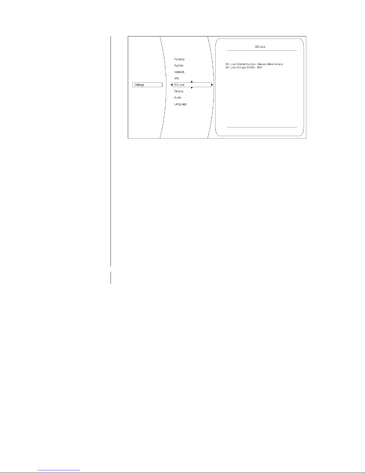
Overview
BD-Live Internet access
The K8 is capable of accessing content (trailers, previews, supplementary
information ...) from the Internet. At this menu point you can define the conditions under which the player is allowed access.
Possible settings are:
Always allow access:
This setting allows the BluRay disc in the K8 to access all requested content.
Limit access:
This setting allows the BluRay disc in the K8 to access only those Internet sites which have a valid on-line certificate.
Prohibit access:
This setting forbids the BluRay disc in the K8 to access any Internet sites
BD-Live storage (USB)
(Erase BD-Live storage)
The
K8
can store Internet content requested by the BluRay disc; to use this
facility an external storage medium is required in the form of a USB memory
stick.
These two options are used to manage and erase the external storage medium.
Leaving the category
When you have entered all the correct settings in this category, you can leave it
by pressing the button.
Page 27
27
Network category (wired network connection)
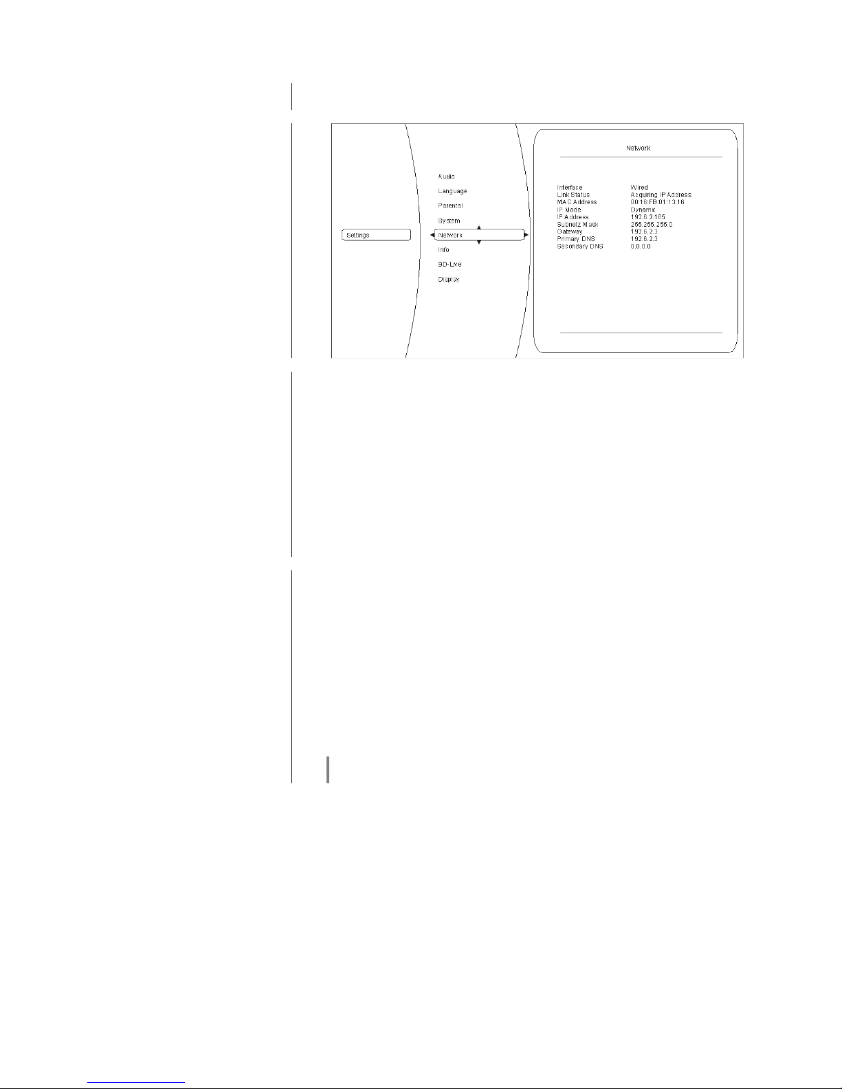
To be able to display BD-Live content, the K8 must have Internet access.
Please connect the UPLINK socket on the back of the machine to your network.
Overview
Interface, connection
status
and MAC address
The first three entries in the network menu are Status messages, i.e. they are
for information purposes only, and cannot be altered. Their function is as follows:
Interface:
(in this case always Cable) indicates that the K8 is connected to the Internet by
a wired connection.
Connection status:
indicates whether the K8 can currently access the Internet (Link up). If 'Link
down' is displayed at this point, please check the connection to your network,
and / or your network settings.
MAC address:
this is a method of identifying your machine, and is required for Internet
communication.
IP mode,
IP address
Sub-net mask,
Gateway,
Primary DNS
Secondary DNS
At this point please state whether the K8 is to obtain the data required for
Internet communication (IP address, sub-net mask, Gateway, DNS) automatically, or whether you wish to configure these data manually.
Dynamic:
the K8 obtains its IP address, sub-net mask, Gateway and DNS address
automatically. For this setting a DHCP-capable device must be present in your
network.
Manual:
in this case you have to enter the IP address, sub-net mask, Gateway and DNS
address manually. Selecting this setting activates the appropriate fields.
Network test
When you have completed the network configuration, you can check the net-
work settings here.
Please contact your network administrator if network access is not set up
correctly.
Page 28

28
Info category
In this menu you will find information about the current version of your machine.
Audio category
This menu cannot be accessed, as the audio settings are entered in the ‘Sys-
tem configuration’ menu of the K8.
Page 29

29
Network Configuration
General Information
The K8 can be used in a wired LAN network (Ethernet LAN or Powerline LAN),
or a wireless radio network (WLAN) if an external “WLAN bridge” is installed.
If you wish to use your K8 in your home network, you must first complete the
necessary network settings on the K8. This involves entering the network parameters such as the IP address, etc.
Please refer to the Chapter 'Glossary / Additional Information' and 'Network
Terms' for additional explanations of terminology relating to network
technology.
In the following sections we assume that a functioning home network
with
router and (DSL) Internet access already exists.
If you are unclear about some aspect of installing, setting up and configuring
your network, please address your queries to your network administrator or a
network specialist.
Compatible hardware
and UPnP servers
The market offers a vast number of routers, NAS devices and USB hard discs
made by a huge variety of manufacturers. devices are generally
compatible with other makes of machine which bear the UPnP label. A list of
units which has checked for compatibility can be found on the Internet
under http://www.ta-hifi.com Support Hardware/Software.
Network Configuration
Menu
All network settings are carried out in the network configuration menu.
Page 30

30
Network settings for the Streaming Client
Opening the Network
Configuration Menu
First select the K8 Streaming Client function by pressing the /
button.
Open the configuration menu with a long press on the button. You
should now see the configuration menu on the front panel screen.
Operating the Menu,
Changing and Storing
IP Addresses
Use the / buttons in the menu to select the network parameter
to be changed, and activate the entry with the button.
You can now change the setting using the following buttons, depending on the
type of setting:
/ button for simple selection (ON / OFF)
Numeric buttons to for entering IP addresses
(remote control handset only)
Alpha-numeric input for entering text
(remote control handset only)
When the setting process is complete, or when you have entered the complete
address, press the button to confirm your action.
Alpha-numeric entry (remote control handset only)
At certain points, e.g. for entering server names or passwords, it is necessary to
input series of characters (strings). At such points you can enter letters, numbers and special characters by repeatedly pressing the numeric buttons on the
F100 / FM100 remote control handset, as when writing SMS news. The
assignment of letters to the buttons is printed below the buttons. Special
characters can be accessed using the and buttons:
0 + - * / ^ = { } ( ) [ ] < >
. , ? ! : ; 1 \ " ' _ @ $ % & # ~
Use the blue button for toggling between numbers, capitals and lowercase letters. The bottom line of the screen shows which input mode is currently
selected.
At certain points (e.g. DNS server name) it is possible to enter both an alphanumeric string and an IP address. At these points an IP address should be
entered like a string (with separating dots as special characters). In this case an
automatic check for valid address ranges (0 … 255) is not carried out.
Closing the Menu
Once you have correctly set all the parameters, select the menu point
'Save
and Restart', then press the button. This action causes the K8 to
accept the settings, and the machine restarts with the new network settings.
After the restart you should see the available network media sources (Internet
radio, UPnP-AV server, etc.) displayed in the main menu.
Interrupting the Menu
without Storing the Settings
At any time you can leave the network configuration menu without making any
changes to the network settings: this is done by pressing the button,
which takes you to the menu point 'Exit without saving'. Pressing the
button at this juncture interrupts and closes the menu.
Page 31
31
The Configuration for a Wired Ethernet LAN or Power-Line LAN connection
Setting the Parameters for a
Wired Network
•
Connect the K8 to an operational network or Power-Line modem using the
LAN socket on the back panel.
• Switch the K8 on, and select the Streaming Client function by pressing the
/ button.
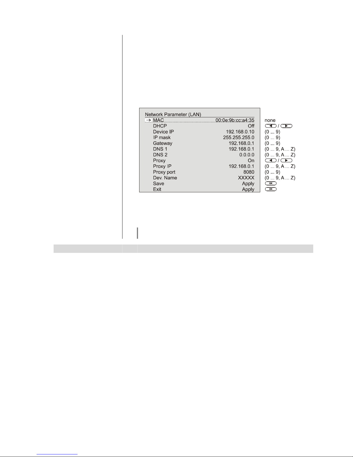
• Call up the Configuration menu as described above. You should now see the
menu reproduced below, displaying the network parameters. In the title line
the message 'LAN' should appear, indicating that the machine is connected
to a wired LAN.
• You can now select the individual menu points and adjust them to match your
network conditions. The illustration below shows the possible button inputs
after each menu point.
Possible entries
/
:Switching ON / OFF
(0...9): Numeric input, separating dots are automatically generated; input
limited to valid addresses
(0...9, A...Z): Alpha-numeric input and special characters.
IP - separating dots must be entered as special characters.
The parameters illustrated above are only typical values.
Addresses and settings may require different values for your network.
Menu Point Description
MAC The MAC address is a hardware address which uniquely identifies your
machine. The address displayed is determined by the manufacturer, and cannot
be altered.
DHCP
ON
If your network includes a DHCP server, please select the ON setting at this
point. In this mode an IP address is automatically assigned to the K8 by the
router. The screen shows only the MAC address and the message DHCP state
ON. In this case the address input fields shown in the illustration do not appear
in the menu.
OFF
If your network does not include a DHCP server, please select the OFF setting.
In this mode you must configure the following network settings manually.
Please ask your network administrator for the addresses to be entered for your
network.
Device IP
IP address of the K8
IP mask
Network mask
Gateway
IP address of the router
DNS 1
Name / IP of the name server (optional)
DNS 2
Alternative name server (optional)
Proxy
ON
if a proxy server is present, otherwise OFF
Proxy IP
Address of the proxy server
Proxy port
Port number of the proxy server
Dev. Name
User-selected name under which the device appears in the network
Save
Stores the network parameters, and restarts the K8 with the new settings.
Exit
Closes the menu: data already entered is discarded.
Page 32
32
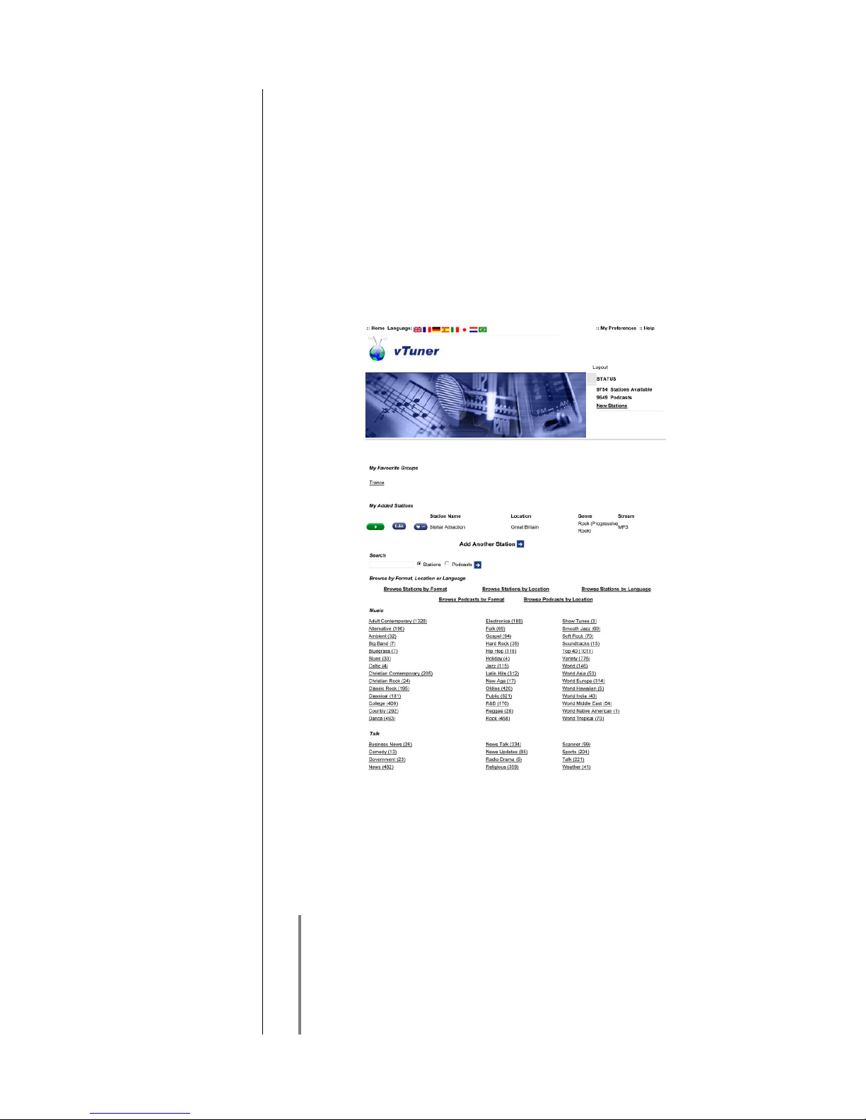
The vTuner Premium Service
The list of radio stations displayed by your K8 is prepared by an Internet
Service Provider, and transferred to your machine by data transfer. You can
expand and edit the 'Favourite Groups' and 'Added Stations' list to suit your
preferences via the Internet portal of your service provider, using the main
menu point 'Internet Radio'. This is the procedure:
Open your Internet browser and call up the following web address:
http://ta.vtuner.com
The first time you register you should enter the MAC address of your K2; the
MAC address provides unique identification of your machine. The MAC address
can be found in the Configuration menu (hold the button pressed in),
and consists of six pairs of characters, e.g.: 00:0e:9b:cc:a4:35. You do not need
to enter the separating colons when you enter this data. MAC addresses are in
hexadecimal format, i.e. the address consists only of the letters a to f, and the
numbers 0 to 9.
Confirm your entry.
You must register with vTuner in order to be able to use the service; you can
register via your e-Mail address and a password. Please follow the instructions
stated by the service provider.
Now you can select radio stations from the comprehensive inventory provided
by vTuner, and store them in lists. The lists are transferred to your K2
automatically via your Internet connection. Shortly after you have edited lists on
the vTuner page, or stored new stations, you will find that they are available on
your K8.
Notes regarding Internet Radio:
• Not all stations are always accessible
-
Not all stations transmit 24 hours
-
Stations are no longer accessible
-
Capacity exhausted
• Transmission breaks off
-
(Internet) network problems
-
Server capacity exhausted
Page 33

33
Setting up new
Internet Radio Stations
On the vTuner Internet site you can also set up new stations which are not (yet)
included in the Select lists. This is accomplished by registering with vTuner and
logging on. Click on the point 'My Added Stations'. An input mask appears in
which you can enter the data for your station. After a brief period you will be
able to access the newly set-up station via the menu system of your K8. You
will find the station under Internet Radio / Added Stations.
Finding
a Station URL
You require the URL (Internet address) of any radio station you wish to set up
on the vTuner service. You will generally find the URL on the station’s website.
Another method of finding the URL is to search for it using an Internet searching
service such as Shoutcast (www.shoutcast.com). Once you have found your
station, click on the 'Tune In' switch: this will normally open your media player,
and the station should play. In most cases you can set Media Player to display
the 'Streaming Properties'. For example, using the popular Winamp Player,
simply right-click on the entry for the currently playing station in the player’s
Playlist window. A menu now opens, and clicking on the point ‘View File Info’
opens an information box which displays the streaming properties including the
URL.
Page 34
34
Connections
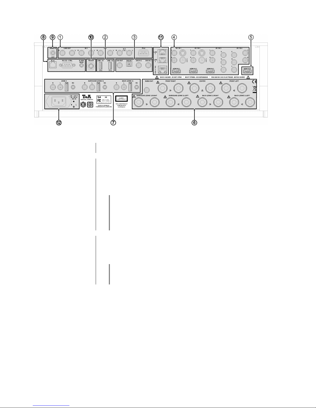
Audio IN
LINE OUT
Analogue audio output (line output), e.g. for analogue recording equipment (TAPE
recorder)
IN1
Analogue stereo audio input.
Select the Audio 1 source in order to hear the source device connected here.
IN2
Analogue stereo audio input.
Select the Audio 2 source in order to hear the source device connected here.
IN3
Analogue stereo audio input.
Select the Audio 3/TV source in order to hear the source device connected
here.
Connecting a TV set for sound reproduction through the K8
If you wish to have the audio signals from your TV reproduced via the K8, connect the stereo sound output of your TV set to the IN3 input.
If your TV set features a digital stereo or surround sound output, connect this to
a digital input (DIG_IN1...DIG_IN3) instead of the analogue input IN3. In this
case you need to assign the appropriate digital input to the source device TV in
the menu 'System Configuration'.
iPod
Socket for an iPod (adapter lead supplied in the set)
An iPod connected to this socket can play audio and video content through the
K8.
To play content, select the iPod as source device with a long press on the SCL
button on the remote control handset.
Please connect the iPod using the iPod lead included in the accessory pack
supplied with the K8, or use the iPod Docking Station with 30-pin
analogue connection (order no. 4362 99201), which is available as an
accessory.
Page 35

35
USB IN
(AUDIO USB)
USB sockets for playing AUDIO files stored on USB memory sticks and iPod
USB-A1 (HDD)
Socket for a USB memory stick or an external hard disc
Audio files from a storage medium connected to this socket are played back
using the Streaming Client (SCL). Select the Streaming Client as source to play
the files. The USB stick appears in the main menu of the Streaming Client,
where it can be selected for playback.
The memory stick must be formatted using the FAT16 or FAT32 file system.
It is not possible to play
video files
via the USB-A1 input.
Please use the USB socket on the front panel for reproducing video files, and
play the files via the USB playback function of the Blu-ray disc player.
The USB memory stick can be powered through the USB socket, provided that
the device’s current drain meets the USB norm (<500 mA). USB hard discs with
a higher current drain require their own mains PSU if they are to be connected
to this socket.
The power supply at this socket is switched off in stand-by mode. Memory
sticks and hard discs powered from this socket can therefore be left connected
even in stand-by mode.
USB-A2 (iPod)
iPod socket for audio playback
Audio content stored on an iPod connected to this socket can be played back
via the Streaming Client (SCL). For playback select the Streaming Client as
source. The iPod appears in the main menu of the Streaming Client, and can be
selected for playback.
Access to the audio files on the iPod is digital, which means that the files are
played back using the K8’s high-quality D/A converter.
To connect the iPod you can either use the USB lead supplied with your iPod,
or the iPod Docking Station with USB socket (order no. 4362 99301),
which is available as an accessory.
An iPod connected to this socket is powered by the K8, which automatically
recharges its battery. If you wish the charge process to continue even when the
K8 is in stand-by mode, please select the “On (Comfort stand-by)” setting in the
menu 'System Configuration / Comfort Standby'.
Video content stored on the iPod cannot be played via this socket. For video
playback please use the analogue iPod socket, and select the iPod as source
device.
Digital inputs and outputs IN
DIG IN 1 / DIG IN 2 / DIG IN 3
Inputs for digital source devices with optical or co-axial digital output (SP/DIF).
Sample rates supported: 44.1 and 48 kHz, 96 kHz, 192 kHz, 16-bit and 24-bit.
To use these inputs, assign the appropriate input to a source device (AUX1..3,
AV_IN 1...4) in the menu 'System-Configuration / Audio-Inputs'.
DIG OUT
Digital SP/DIF co-axial output for connecting an external digital / analogue con-
verter or digital recorder.
The output delivers two-channel PCM stereo signals.
Page 36
36
AV IN
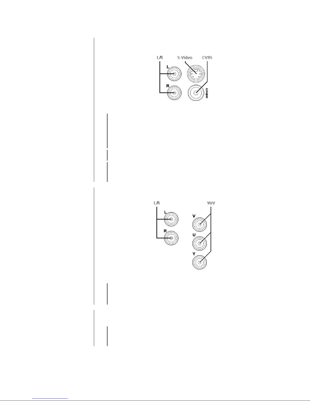
AV IN 1
(CVBS socket, DC-coupled)
AV IN 2 (AC-coupled)
(CVBS socket, AC-coupled)
(Composite, S-Video)
Sockets for connecting analogue AV devices with composite (FBAS) or S-Video
outputs
CVBS = Composite video input
L/R = Analogue stereo input
The CVBS input socket of the
AV IN 1
input is DC-coupled. This gives the best
possible reproduction quality.
Any device connected here must supply a CVBS video signal with D.C.
component (0.5 …2 V), otherwise it will not be possible to process the
video signal.
If the video signal has no D.C. offset, the TV monitor displays no picture. Please
use the AC-coupled CVBS input AV IN 2 for such signals.
Only one of the S-Video and CVBS sockets may be used. You must set up the
socket you have selected in the 'System Configuration / Video-Inputs' menu.
If the AV device connected to the system features a digital audio output, one of
the digital inputs of the K8 (DIG_IN 1...3) can be used instead of the analogue
(L/R) audio inputs. Assign the digital input to the appropriate AV input in the
'System-Configuration / Audio-Inputs' menu.
AV IN 3
AV IN 4
Component AV inputs
For connecting analogue AV devices with YUV component output
YUV = Video input
L/R = Analogue stereo input
If the AV device connected to the system features a digital audio output, you
can use one of the digital inputs of the K8 (DIG_IN 1...3) instead of the
analogue (L/R) audio inputs. Assign the digital input to the appropriate AV input
in the 'System-Configuration / Audio-Inputs' menu.
HDMI IN 1
HDMI IN 2
HDMI IN 3
HDMI inputs for connecting HDMI source devices.
It is possible to connect devices with any SMPTE resolution up to 1080p.
The HDMI IN 3 socket is equipped with the
HEC
(HDMI Ethernet Channel)
function, i.e. a device connected to this socket can be connected to the network
(Internet) via the K8. This also requires the source device to support the HEC
function. The K8 must be connected to your network via the UPLINK socket.
Page 37

37
TV OUT
HDMI OUT
HDMI output for Plasma / LCD TV panel or beamer
The video signals from the internal BD player, or the HDMI and analogue AV
sources connected to the system, can be played back via this output.
If necessary, enter the appropriate settings in the Video Setup menu.
If the TV set connected to the system features the
ARC
(Audio Return Channel)
function, audio signals from the TV set can be passed to the K8 via the HDMI
lead. This function makes very good sense if the TV set features an integral TV
receiver. Surround programmes (Dolby Surround, Dolby Digital+ etc.) can then
be passed to the K8 for decoding without requiring additional cables.
If the TV set connected to the system features the
HEC
(HDMI Ethernet Chan-
nel) function, the TV set can be connected to the Internet via the K8 and the
HDMI lead. This requires the K8 to be connected to an Internet router (see
UPLINK socket).
Page 38

38
Loudspeaker outputs and sub-woofer
Caution!
The connections marked
are hazardous, and must not be touched.
Connections between external cables and these points must be carried out by
trained personnel; alternatively ready-made cables must be used.
Caution!
Ensure that the screw-terminals are firmly tightened. Check for stray cable
strands which could cause short-circuits.
Caution!
The impedance of the loudspeakers connected to the system should not be
lower than 4 Ω (DIN).
The output stages are designed for a minimum load of 2 Ω, but if the machine is
run for protracted periods at high volume with this load, the high currents may
cause the power amplifiers to overheat, which would cause the protective circuit
to shut down the system automatically.
After connecting the loudspeakers, please complete the necessary settings for
your speaker configuration in the System configuration /
Loudspeakerconfiguration menu.
If you live outside the countries of the EU, you may wish to remove the red /
black stoppers from the loudspeaker terminals. In this case the speakers can be
connected using banana plugs.
The stoppers are only a push-fit in the terminals. They can be levered out of the
back of the terminal using a suitable tool (e.g. knife blade).
The accessory range includes a selection of high-quality cables which are
designed to be a perfect match to equipment.
FRONT RIGHT
FRONT LEFT
Front speaker terminals
The main loudspeakers are those located at front right and left in the room.
They are connected to these terminals.
CENTER
Centre speaker terminals
If your system includes a central front loudspeaker situated adjacent to the TV
set or projector screen, it should be connected to these terminals.
BACK (ZONE 2) RIGHT
BACK (ZONE 2) LEFT
Terminals for the BACK speakers
of a 7.1 surround system.
In a 7.1 system the rear (back) loudspeakers, located at rear right and left in the
room, are connected to these terminals.
If the BACK speaker terminals are not used for 7.1 surround in the main listening room, supplementary speakers for an additional listening zone / adjacent room can be connected to these terminals.
SURROUND (ZONE 3) RIGHT
SURROUND (ZONE 3) LEFT
In a 5.1 system the rear surround speakers are connected to these terminals. In
a 7.1 system the right and left surround speakers are connected here.
If the SURROUND speaker terminals are not used for 5.1 or 7.1 surround in the
main listening room, supplementary speakers for an additional listening zone /
adjacent room can be connected to these terminals.
SUBW OUT
Output socket for an active sub-woofer.
A sub-woofer is optional.
If your system includes a sub-woofer, it must be switched on in the Loudspeaker menu (see the Chapter ‘System settings, Loudspeakers).
If no sub-woofer is present in your system, it is essential to disable the subwoofer in the Loudspeaker menu (see the Chapter entitled ‘System settings,
loudspeakers’) (‘Sub-woofer off’ setting).
If no sub-woofer is present in the system, but the sub-woofer is not disabled in
the ‘Loudspeaker settings’ menu (Chapter ‘System settings’), then the lowfrequency part of the sound range will be absent from the system’s sound.
Page 39

39
Pre AMP OUT
Pre-amplifier outputs
ZONE 4
Pre-amplifier output for providing sound in an additional listening zone using ac-
tive loudspeakers or an audio radio module.
SURROUND (ZONE3)
Pre-amplifier output for connecting active loudspeakers or an audio radio
module for the SURROUND channels.
If the SURROUND channels are not used for a 5.1 or 7.1 channel surround
system in the main room, active speakers or an audio radio module can be connected here to provide sound in an additional listening zone.
BACK (ZONE2)
Pre-amplifier output for connecting active loudspeakers or an audio radio
module for the BACK channels.
If the BACK channels are not used for a 7.1 channel surround system in the
main room, active speakers or an audio radio module can be connected here to
provide sound in an additional listening zone.
RC
The RC sockets in each connector field can be used to connect an E2000 ex-
ternal infra-red remote control receiver. The K8 can be controlled remotely from
the associated listening zone using receivers connected here.
PWR
The PWR sockets function as the power supply for a
T+A
audio radio module.
The PWR sockets deliver +5 V / 500 mA.
Please use these sockets only for the recommended genuine T+A supplementary devices.
If you wish to connect other makes of equipment, you must ensure that they
conform to the connection data stated above.
System control
E
LINK
Control output socket for the E
LINK
system.
RS 232
Software update interface, also used to control external devices.
The K8 can be used to control particular
METZ
and
LOEWE
TV sets with
specific features, using the appropriate control lead which is available as
an optional accessory.
For more information please contact your specialist dealer.
This interface can also be employed for computer-controlled operation of device
functions, making it possible to control the K8 remotely using home automation
systems such as those made by CRESTRON, AMX, etc.
The K8 must have special software installed if you wish to control it externally.
For detailed information on the RS 232 interface, the protocol required and
command lists please refer to the Technology and Download areas of the
website http://www.ta-hifi.com.
E2000 MAIN
Input socket for the E 2000 remote control receiver.
This socket can be used if the K8 is to be set up in a concealed location (e.g. in
a cabinet, behind glass doors, etc.), and the remote control receiver installed in
the front panel does not respond to the infra-red signals generated by the
remote control handset.
Page 40

40
Remote aerial
Radio aerial socket
Socket for retro-fitting the K8 with a radio gateway module for the T+A FD100
graphic radio remote control system (under development).
FM aerial
75 Ω VHF / FM aerial input
This socket is suitable for the standard domestic aerial and also for a cable connection.
If you wish to obtain first-class reception quality, a competently installed highperformance aerial system is a fundamental requirement.
Network
LAN
Sockets for a wired network (LAN)
LAN output sockets for other devices (TV, games console, etc.)
The K8 can provide an Internet network connection to other devices via these
sockets, provided that it is itself connected to your network router using its
UPLINK socket.
UPLINK
(LAN input)
Socket for a network connection to your network router or Internet access point.
Connect this socket to your network router if you wish to be able to exploit
Internet radio and audio streaming from a UPnP server, or the BD-Live functions of the K8’s integral Blu-ray player.
If there is no wired LAN network available at the system’s location, we
recommend using a Power-Line modem rated at a minimum of 85 Mbps, which
transmits the data over the mains cables.
An alternative is to employ what is known as a WLAN bridge, which converts
WLAN signals into LAN signals.
Mains input
The mains cable is plugged into this socket.
Please read the notes in the Chapters entitled
‘Using the machine for the first
time, Wiring’ and ‘Safety Notes’ to be sure of connecting the unit to the mains
in the required manner.
Page 41

41
Listening zones, sound in adjacent rooms
In addition to the primary speakers in the main room, the K8 can provide a signal to loudspeakers in other listening zones or adjacent rooms. The number of
additional listening zones varies according to the speaker configuration in the
main room:
Main room with 7.1 channel surround configuration
Sound can be provided in one additional zone. This zone is connected to the
pre-amplifier outputs marked “ZONE 4”. The actual sound can be provided by
any of the following: active speakers, radio transmission modules or passive
speakers with an additional (external) power amplifier.
Main room with 5.1 channel surround configuration
In this case the rear channels are available in addition to zone 4, as they are
not used for a 5.1 surround system. Sound can be provided in a further listening
zone (Zone2) using these channels. The following wiring variants are available:
• BACK loudspeaker outputs / Zone 2 for passive loudspeakers
• ZONE 2 pre-amplifier outputs for active speakers or radio transmission
modules
Main room with stereo (2.1 / 2.0) or 3-channel (3.1 / 3.0) loudspeaker configuration
In this case the surround channels are available in addition to zones 2 and 4, as
they are not used for a stereo or three-channel configuration. Sound can be
provided in a third additional listening zone (Zone3) using these channels. The
following wiring variants are available:
• SURROUND loudspeaker outputs / Zone 3 for passive loudspeakers
• ZONE 3 pre-amplifier outputs for active speakers or radio transmission
modules
Volume control for additional listening zones and adjacent rooms
In the 'System Configuration / Loudspeakerconfiguration / Loudspeaker'
menu you can determine individually for each of the listening zones 2, 3 and 4
whether the volume is to be variable independently (SEPARATE), whether it is
to alter in parallel with the main room volume (LINKED), or whether a fixed level
is to be set at the listening zone output (FIXED).
Zone volume coupled to main room (LINKED)
The volume in the listening zone varies in parallel with that of the main room
loudspeakers. This mode of operation is suitable, for example, where sound is
to be provided in a second listening zone within the same room (e.g. dining
area). If you wish the volume to be slightly damped in one of the areas, you can
set a difference in level between the main speakers and the listening zone in
the menu 'System Configuration / Loudspeakerconfiguration /
Loudspeaker'.
Zone volume separately variable (SEPARATE)
The volume in the listening zone is adjusted independently of the main room
loudspeakers. In this case the E2000 external remote control receiver (included
in the accessory pack) must be connected to the RC input of the listening zone
concerned, and installed in the adjacent room. If you now alter the volume in
the adjacent room by remote control, then the change only affects the volume of
the listening zone concerned, i.e. the volume in the main room remains unchanged. The listening zone output can only be switched on and off using the
remote control handset in the adjacent room.
Non-variable zone volume, fixed level (FIXED)
This mode of operation is suitable when using loudspeakers or radio modules
which feature their own volume control system. In this mode the volume level
cannot be adjusted using the T+A remote control system. To vary the volume in
the zone, use the volume control of the loudspeakers connected to the system,
or the radio module.
Note: even in fixed level mode the remaining functions of the K8 (station
change, track skip, etc.) can still be operated using an E2000 remote control
receiver connected to the RC input for the zone.
.
Page 42
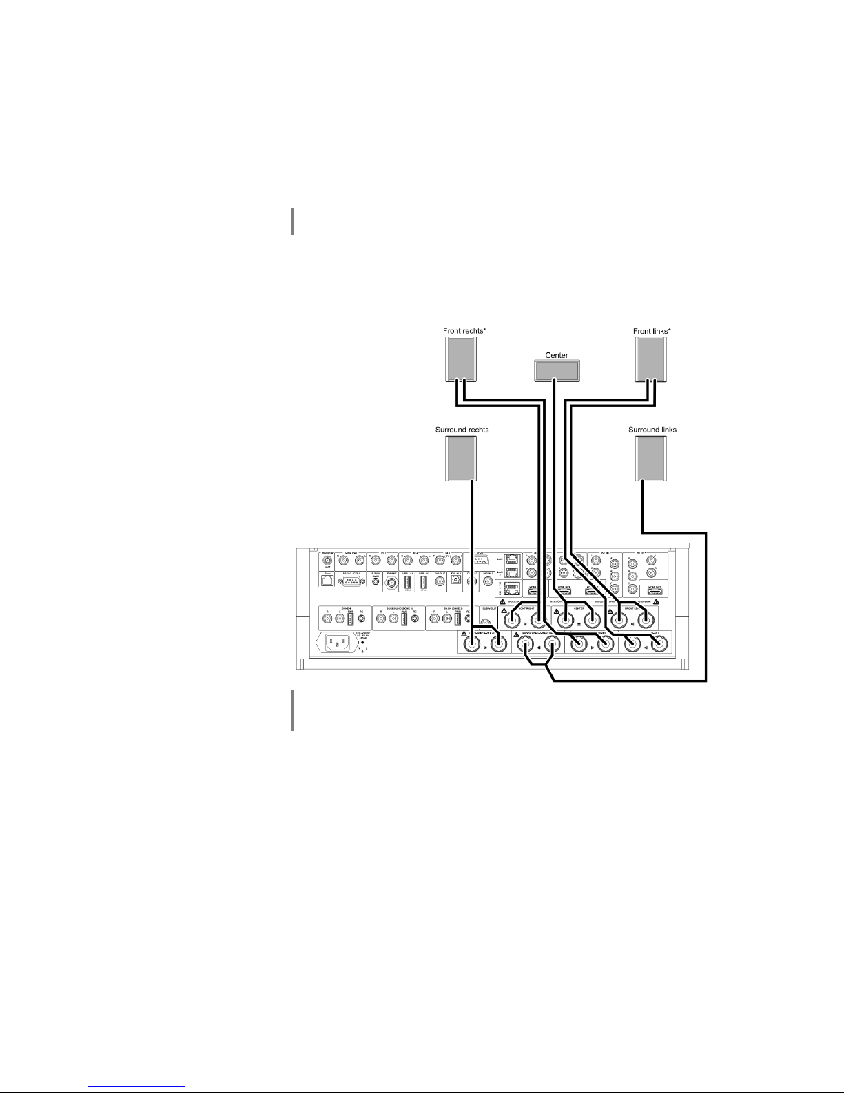
42
Special operation modes
General
For special applications which are not covered by the range of configurations
listed in the chapter entitled 'Listening zones, sound in adjacent rooms', two
optional special modes of operation are available: Bi-Amping for the main
loudspeakers, and the option of using the Zone 4 output as Pre-Out for the front
channels. Since these special modes are configured by means of jumpers
inside the K8, the machine’s case must be opened. This work must be carried
out by a qualified technician exclusively; please contact your specialist
dealer for details.
This special modes of operation are available since K8 serial number
2111 3230 00152.
Bi-Ampi
ng
The K8 is equipped with seven identical power amplifiers. If used in a 5.1 setup
the power amps of the BACK channels can be used for Bi-Amping in
conjunction with the main FRONT_L and FRONT_R amps instead of using
them for a second zone.
*only for speakers having bi
-
amping terminals with electrical isolation
between Bass and Mid/Treble sections
(do not connect the amplifier outputs in parallel !)
Settings
you have to activate the BACK speakers in the speaker-menu. (These speaker
outputs now function as Bi-Amping front outputs)
Page 43
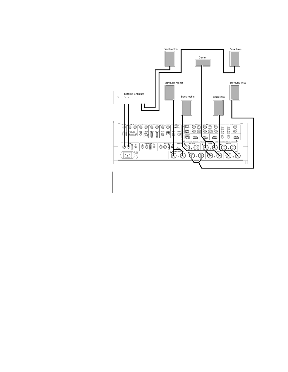
43
Zone 4 as Pre
-
Out
put
(Operation with active
speakers or external
amplifiers for the front
channels)
Instead using the internal power-amps, active speakers or external amplifiers
can be used for the FRONT_L and FRONT_R channels. For this purpose the
ZONE_4 Pre-Output can be re-configured as Pre-Amp out for the main
channels.
Please be aware that in this configuration ZONE 4 cannot be used for an
additional room.
If a head phone is connected, the ZONE 4 (now Pre Out) sockets won't be
muted!
Page 44
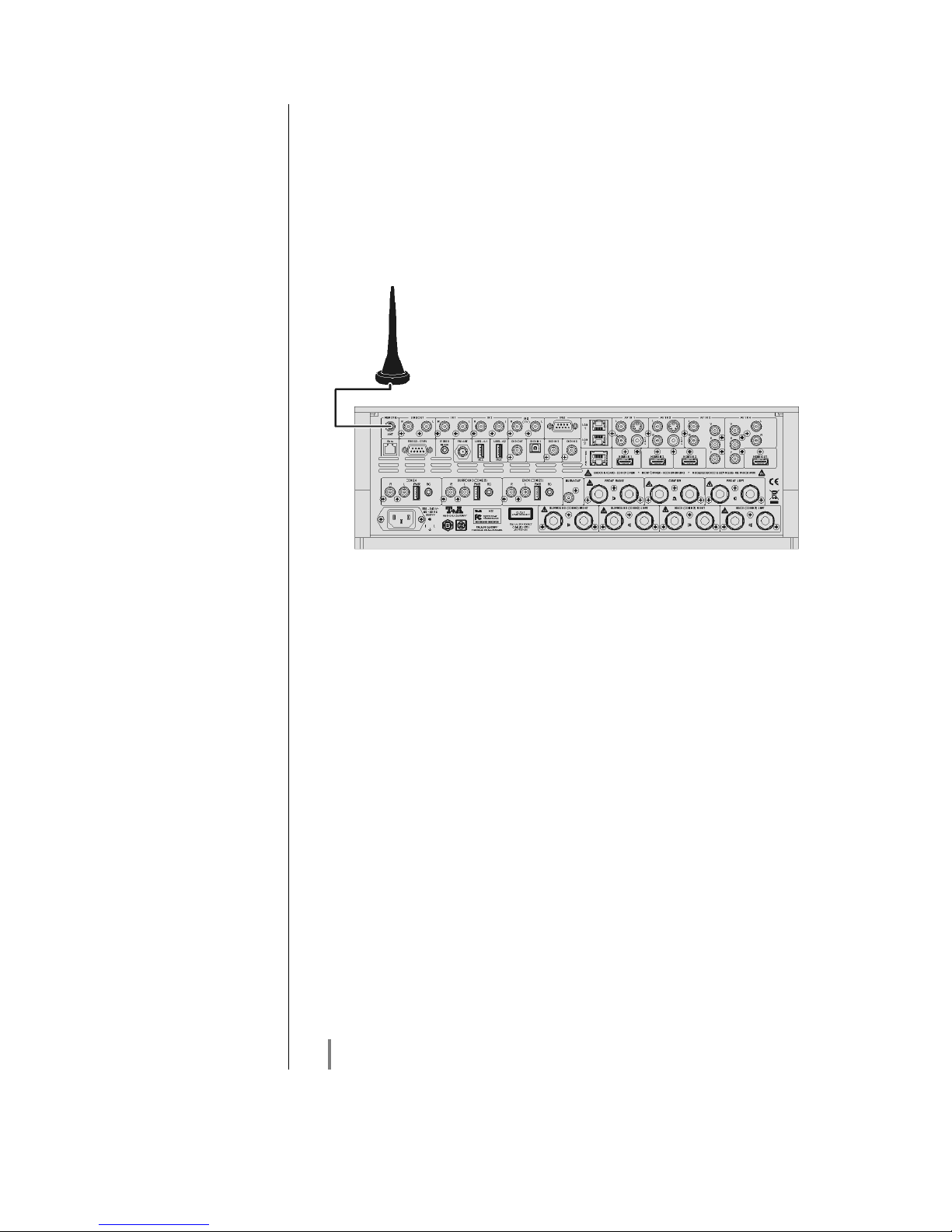
44
FD 100 Radio Remote Control
The K8 can be controlled remotely using the FD 100 bi-directional radio remote
control handset if a Gateway module is installed; this is available as an optional
extra. The FD 100 features an integral full-colour screen which provides a
convenient means of controlling virtually all the K8’s functions, even when there
is no direct line-of-sight contact with it. The handset can also display information
relating to the selected source or the medium currently playing.
Connecting the radio aerial
Since the FD 100 operates by a radio link, an aerial must be connected to the
K8. This is plugged into the socket on the K8 marked ‘Remote ANT’. The aerial
should be free-standing in order to obtain maximum effective range.
Pairing the FD
100
Before the K8 can be controlled using the FD 100, the remote control handset
must first be registered to the K8. This process is known as pairing, and only
has to be carried out once. The procedure is as follows:
• Press the button on the K8 to call up the Configuration menu,
then select the ‘FD 100 pairing’ menu point using the button.
• To confirm the pairing process of the FD 100, press the button
until the menu entry changes to 'waiting for FD 100'. (the function
remains active for thirty seconds).
• Locate the button on the FD 100 and hold it pressed in to open
the FD 100’s System Settings menu.
• Now select the ‘Start pairing’ point, and press the button: the
remote control handset automatically seeks the K8.
• Once the device is found, you will see in the display header the on-
screen message ‘Pairing successful’. At the same time changes the
menu entry of the K8 to 'Done'. If you wish, you can change the name
of the device at this point (eg. 'Living room').
• Confirm the name with the button.
• For faster access the K8 can also be assigned to a Hotkey; this is the
next step (see FD 100 operating instructions).
• Select one - or optionally none - of the ‘F’ buttons, and confirm your
choice by pressing the button.
The FD 100 is now paired with the K8, and is ready for use.
For detailed information on using the FD 100 please refer to the operating
instructions supplied with the remote control handset.
Page 45

45
Displaying iPod content on the FD 100 graphic remote control handset
There are two possible methods of connecting an iPod to the K8. Please note
the following points when using the FD 100 to control the system:
'iPod' connection
Music and video playback
If an iPod is connected to the analogue ‘iPod’ socket, playback of music
and
video content is supported. In this case the iPod’s screen is used for navigation,
while the K8 or the iPod itself is used to control operations. With this mode of
connection the FD 100 can only control the iPod. The iPod passes no information to the K8 through this connection, and therefore the FD 100 has no
information to display.
'USB-A2 (iPod) connection'
Music playback only
The second method of connecting the iPod is to use the streaming client’s USB-
A2 socket, which provides a convenient means of controlling the iPod with the
FD 100. In this mode of operation the iPod does pass the requisite information
to the K8, but the iPod does not support video playback via the K8; this configuration therefore allows only pure audio playback. Instead of appearing as its
own source, the iPod is now listed amongst the streaming client’s available
media and devices. In this mode navigation and operation of the iPod are
carried out exclusively via the K8’s ‘Streaming Client’ source, and the iPod is
operated using the same method described for operating the streaming client
(see section ‘Operating the streaming client’).
If you wish to have content and information displayed on the FD
100’s
integral screen when navigating and playing back the iPod, the only
option is to connect the iPod to the USB socket, since the iPod only
delivers the information required for the display when this form of connection is used.
Page 46

46
Installation and wiring
Carefully unpack the K8 and store the original packing materials carefully. The
carton and packing are specially designed for this unit and will be needed again
if you wish to move the equipment at any time.
Please be sure to read the safety notes in these instructions.
If the unit gets very cold (e. g. when being transported), condensation may form
inside it. Please do not switch it on until it has had plenty of time to warm up to
room temperature, so that any condensation evaporates completely.
Before placing the unit on a sensitive surface, please check the compatibility of
the lacquer and the unit’s feet at a non-visible point.
The K8 must not be set up on a heat
-
sensitive su
rface, as the machine
can heat up to 60°C in use. If you wish to use such a surface, one solution
is to place an insulating layer between the machine and the surface.
The unit should be placed on a rigid, level base.
The quality and characteristics of the base on which your high-quality HiFi equipment stands define the limits of sound quality which can be
achieved. The base surface should be as heavy, rigid, hard and level as
possible. Make sure there are no loose objects on the support surface
which could cause rattling noises or resonance effects.
The K8 should be set up in a dry, well-ventilated site, out of direct sunlight and
away from radiators.
The unit must not be located close to heat-producing objects or devices, or
anything which is heat-sensitive or highly inflammable.
When installing the unit on a shelf or in a cupboard it is essential to provide an
adequate flow of cooling air, to ensure that the heat produced by the unit is
dissipated effectively. Any heat build-up will shorten the life of the unit and could
be a source of danger. Be sure to leave at least 10 cm free space above the
unit for ventilation. If the system components are to be stacked then the
amplifier must be the top unit. Do not place any object on the top cover.
Mains and loudspeaker cables, and also remote control leads must be kept as
far away as possible from signal leads and antenna cables. Never run them
over or under the unit.
A complete connection diagram is shown in 'Appendix A'.
Notes on connection
s:
• Be sure to push all plugs firmly into their sockets. Loose connections can
cause hum and other unwanted noises.
• When you connect the input sockets of the amplifier to the output sockets on
the source devices always connect like to like, i. e. 'R' to 'R' and 'L' to 'L'. If
you fail to heed this then the stereo channels will be reversed.
• To achieve maximum possible interference rejection the mains plug should be
connected to the mains socket in such a way that phase is connected to the
mains socket contact marked with a dot (). The phase of the mains socket
can be determined using a special meter. If you are not sure about this,
please ask your specialist dealer.
We recommend the use of the 'POWER LINE' ready-to-use mains lead in
conjunction with the 'POWER BAR' mains distribution panel, which is fitted with
a phase indicator as standard.
When you have completed the wiring of the system please set the volume
control to a very low level before switching the system on.
The screen on the K8 should now light up, and the unit should respond to the
controls.
If you encounter problems when setting up and using the amplifier for the first
time please remember that the cause is often simple, and equally simple to
eliminate. Please refer to the section of these instructions entitled 'Trouble
shooting'.
Page 47

47
Loudspeaker and signal
cables
Loudspeaker cables and signal cables (inter-connects) have a significant
influence on the overall reproduction quality of your sound system, and their
importance should not be under-estimated. For this reason recommends
the use of high-quality cables and connectors.
Our accessory range includes a series of excellent cables and connectors
whose properties are carefully matched to our speakers and electronic units,
and which harmonise outstandingly well with them.
For difficult and cramped situations the range also includes special-length
cables and special-purpose connectors (e. g. right-angled versions) which can
be used to solve almost any problem concerning connections and system
location.
Mains cables and mains
filters
The mains power supply provides the energy which your sound system
equipment needs, but it also tends to carry interference from remote devices
such as radio and computer systems.
Our accessory range includes the specially shielded 'POWER FOUR' mains
cable, ready-to-use 'POWER LINE' mains cable with integrated shell-type filters
and the 'POWER BAR' mains filter distribution board which prevent electromagnetic interference from entering your Hi-Fi system. The reproduction quality
of our systems can often be further improved by using these items.
If you have any questions regarding cabling please refer to your specialist
dealer who will gladly give you comprehensive expert advice without obligation.
We would also be happy to send you our comprehensive information pack on
this subject.
Changing the batteries
The battery compartment can be opened by pressing in the locking surface and
sliding the cover down and off. Remove the old cells and fit three new dry cells
of the LR 03 (MICRO) type in the battery compartment, taking care to fit them
with correct polarity. Please remember that all the cells must be replaced at
the same time.
Caution!
Batteries shout not be exposed to excessive heat like sunshine, fire or the like.
Disposing of exhausted batteries:
Exhausted batteries must never be thrown into the household waste! They
should be returned to the battery vendor (specialist dealer) or your local toxic
waste collection point, so that they can be recycled or disposed in a proper way.
Most local authorities provide collection centres for such waste, and some
provide pick-up vehicles for old batteries.
Care of the unit
Always disconnect the unit from the mains supply before cleaning it.
The surfaces of the case should be wiped clean with a soft, dry cloth only.
Never use solvent-based or abrasive cleaners!
Before switching the unit on again, check that there are no short-circuits at the
connections, and that all cables are plugged in correctly.
Page 48

48
Safety notes
All the components in this device fulfil the currently valid German and European
safety norms and standards.
We ensure that our products are of consistently high quality, and meet all
specifications, by checking all materials rigorously for quality, using meticulous
production methods and subjecting each unit to a fully automatic computercontrolled final inspection.
For your own safety please consider it essential to read these operating
instructions right through, and observe in particular the notes regarding setting
up, operation and safety.
Installation
The unit must be set up in such a way that none of the connections can be
touched directly (especially by children). Be sure to observe the notes and
information in the section 'Installation and Wiring'.
Power supply
The power supply required for this unit is printed on the mains supply socket.
The unit must never be connected to a power supply which does not meet
these specifications. If the unit is not to be used for a long period disconnect it
from the mains supply at the wall socket.
Mains leads
/ Mains plug
Mains leads must be deployed in such a way that there is no danger of damage
to them (e. g. through persons treading on them or from furniture). Take
particular care with plugs, distribution panels and connections at the device.
Unplugging the mains plug will disconnect the device from the mains for service
and repair. Please make sure that the mains plug is easily accessible.
Enclosure openings
Liquid or particles must never be allowed to get inside the unit through the
ventilation slots. Mains voltage is present inside the unit, and any electric shock
could cause serious injury or death. Never exert undue force on mains
connectors.
Protect the unit from drips and splashes of water; never place flower vases or
fluid containers on the unit.
Service,
Damage
Like any other electrical appliance this device should never be used without
proper supervision. Take care to keep the unit out of the reach of small children.
Reparation and damage
The case should only be opened by a qualified specialist technician. Repairs
and fuse replacements should be entrusted to an authorised specialist
workshop. With the exception of the connections and measures described in
these instructions, no work of any kind may be carried out on the device by
unqualified persons.
If the unit is damaged, or if you suspect that it is not functioning correctly,
immediately disconnect the mains plug at the wall socket, and ask an
authorised specialist workshop to check it.
Over voltage
The unit may be damaged by excess voltage in the power supply, the mains
circuit or in aerial systems, as may occur during thunderstorms (lightning
strikes) or due to static discharges.
Special power supply units and excess voltage protectors such as the ? 'Power
Bar' mains distribution panel offer some degree of protection from damage to
equipment due to the hazards described above.
However, if you require absolute security from damage due to excess voltage,
the only solution is to disconnect the unit from the mains power supply and any
aerial systems.
To avoid the risk of damage by overvoltages we recommend to disconnect all
cables from this device and your HiFi system during thunderstorms.
All mains power supply and aerial systems to which the unit is connected must
meet all applicable safety regulations and must be installed by an approved
electrical installer.
Many insurance companies offer lightning damage insurance for electrical
equipment as part of their household insurance service.
Page 49

49
Approved
usage
This device is designed exclusively for reproducing sound and/or pictures in the
domestic environment. It is to be used in a dry indoor room which meets all the
recommendations stated in these instructions.
Where the equipment is to be used for other purposes, especially in the medical
field or any field in which safety is an issue, it is essential to establish the unit’s
suitability for this purpose with the manufacturer, and to obtain prior written
approval for this usage.
equipment which includes a radio or television receiving section must be
operated within the stipulations laid down by the Post Office and the
Telecommunications authorities in the country in which it is used.
This unit may only be used to receive or reproduce those transmissions which
are intended for public reception. The reception or reproduction of other
transmissions (e. g. police radio or mobile radio broadcasts) is prohibited.
Approval and conformity
with EC directives
In its original condition the unit meets all currently valid European regulations. It
is approved for use as stipulated within the EC.
By attaching the symbol to the unit declares its conformity with the EC
directives 2006/95/EC and 2004/108/EC and the national laws based on those
directives.
The original, unaltered factory serial number must be present on the outside of
the unit and must be clearly legible! The serial number is a constituent part of
our conformity declaration and therefore of the approval for operation of the
device.
The serial numbers on the unit and in the original documentation supplied
with it (in particular the inspection and guarantee certificates), must not be
removed or modified, and must correspond.
Infringing any of these conditions invalidates conformity and approval, and
the unit may not be operated within the EC. Improper use of the equipment
makes the user liable to penalty under current EC and national laws.
Any modifications or repairs to the unit, or any other intervention by a workshop
or other third party not authorised by , invalidates the approval and
operational permit for the equipment.
Only genuine accessories may be connected to the unit, or such auxiliary
devices which are themselves approved and fulfil all currently valid legal
requirements.
When used in conjunction with auxiliary devices or as part of a system this unit
may only be used for the purposes stated in the section 'Approved usage'.
Disposing of this product
The only permissible method of disposing of this product is to take it to your
local collection centre for electrical waste.
FCC Information to the
user
(for use in the United States of America only)
Class B digital device – instructions:
Note: This equipment has been tested and found to comply with the limits for a
Class B digital device, pursuant to Part 15 of the FCC Rules. These limits are
designed to provide reasonable protection against harmful interference in a
residential installation. This equipment generates, uses and can radiate radio
frequency energy and, if not installed and used in accordance with the
instructions, may cause harmful interference to radio communications.
However, there is no guarantee that interference will not occur in a particular
installation. If this equipment does cause harmful interference to radio or
television reception, which can be determined by turning the equipment off and
on, the user is encouraged to try to correct the interference by one or more of
the following measures:
-
Reorient or relocate the receiving antenna.
-
Increase the separation between the equipment and receiver.
-
Connect the equipment into an outlet on a circuit different form that to which
the receiver is connected.
-
Consult the dealer or an experienced radio/TV technician for help.
Page 50
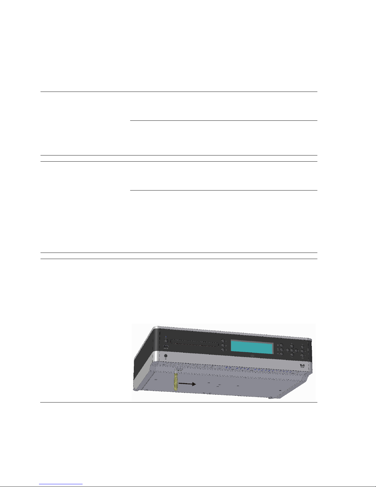
50
Trouble shooting
Many problems have a simple cause and a correspondingly simple solution. The following section describes a few
difficulties you may encounter, and the measures you need to take to cure them. If you find it impossible to solve a
problem with the help of these notes please disconnect the unit from the mains and ask your authorised specialist
dealer for advice.
General:
Machine does not switch on
(the screen remains dark).
Cause 1:
Mains lead not plugged in correctly.
Remedy:
Check connection, push connector in firmly.
Cause 2:
Mains fuse burned out.
Remedy:
Have the mains fuse replaced by an authorised specialist workshop. The rating
of the replacement fuse must agree with the specification printed on the unit.
Machine responds correctly
to manual operation of the
buttons, but can not be
controlled by IR remote
control.
Cause 1:
Incorrectly inserted batteries or flat batteries in the remote control handset.
Remedy:
Re-install batteries correctly or fit new ones.
Cause 2:
The remote control transmitter has no direct line-of-sight with the unit.
Remedy:
Make sure that the remote control transmitter has direct line-of-sight contact
with the receiver - note that glass doors can interrupt the connection.
Maximum range between transmitter and receiver: approx. 8 metres.
Be sure to position the receiver where it is not subjected to direct sunlight or
very bright artificial light. Fluorescent tubes and energy-saving lamps are
powerful sources of interference.
Disc drawe
r does not open.
Cause:
Mechanical blockage, jammed disc, faulty disc mechanism.
Remedy:
Open the disc drawer manually.
First switch the machine off (disconnect the mains plug). You will find an
opening in the bottom through which you can disengage the disc drawer by
pushing the white disengagement slider fully to the left using a suitable screwdriver. This will cause the drawer to open by a few millimetres, and you can
then extend it fully by hand.
Page 51

51
Ton:
Very weak bass response
Cause 1:
The loudspeakers are connected out of phase.
Remedy:
Check that the positive terminal of each loudspeaker is connected to the
appropriate positive loudspeaker terminal on the K8.
There are also Test-CDs which provide a simple means of determining correct
loudspeaker phase. Please ask your local specialist dealer about this.
Cause 2:
You have set a cross-over frequency for the loudspeakers (and perhaps also for
the Centre speaker) in the System configuration menu / Loudspeaker
configuration / Loudspeaker, even though no sub-woofer is present in the
system.
Remedy:
Either connect a sub-woofer to the system, or select the “Full-range” setting in
the Loudspeaker configuration menu for the L / R front loudspeakers (and also
for the Centre, if present). If you are using small loudspeakers, select the
“Large” setting.
Cause 3:
Unfavourable loudspeaker position, or loudspeakers too small for the size of
room.
Remedy:
Use loudspeakers of adequate size, matched to the size of the listening room.
You may wish to try different locations in order to obtain a more favourable dispersion pattern.
Note: siting speakers close to a wall or in a corner amplifies the bass response.
Page 52

52
Picture:
No picture from the DVD
player.
Cause 1:
Video lead not connected, or defective.
Remedy:
Connect the video lead properly; have the lead checked by an expert.
Cause 2:
Video monitor not set to the correct picture input, or an incorrect video norm
selected for the input.
Remedy:
Select the picture input (AV input) on the video monitor to which your K2 is
connected.
If you are using a SCART input, please check whether the video norm (FBAS,
S-Video, RGB, YUV) is set to match the output of the K8 which is in use.
No picture from the iPod.
Cause 1:
Video output switched off at the iPod.
Remedy:
Switch on video output on your iPod.
Cause 2:
Your iPod does not support video output.
Remedy:
Ensure that you are using a model of iPod which supports video output.
No pict
ure at AV input AV IN
1
Cause:
The CVBS input socket of the AV IN 1 input is DC-coupled. Any device
connected here must supply a CVBS video signal with D.C. component (0.5 …2
V), otherwise it will not be possible to process the video signal.
If the CVBS video signal has no D.C. offset, the TV monitor displays no picture.
Remedy:
Please use the AC-coupled CVBS input AV IN 2 for CVBS signals without D.C.
offset.
Jerky picture with BluRay
or DVD reproduction
Cause:
The set frame rate does not match the disc being played.
Remedy:
Wherever possible, select the “AUTO” setting In the Display Resolution point of
the BluRay setup menu. The K8’s BluRay player will then automatically set itself
up correctly to suit the capabilities of your monitor and the requirements of the
disc.
If you select a setting other than AUTO, then you must also enter the correct
setting under “Colour system” to suit the disc you wish to play.
Select for
PAL-DVD := PAL (50 Hz),
NTSC-DVD := NTSC (60 Hz)
BluRay:= PAL or NTSC - according to the disc. If no information is
stated on the BluRay disc, you can only establish the correct
frame rate by practical testing.
When you change the disc, you may need to adjust the frame rate again to suit
the requirements of the new disc.
Page 53

53
Streaming Client
The streaming client can
not connect to a network.
On the display the
indication
'SCL Connecting...'
is displayed.
Cause 1 (cable LAN):
Network cable not properly connected
Remedy:
Connect network cable, check connection to router
Cause 2:
Network parameters not properly configured.
Remedy:
Configure the network parameters correctly (see chapter 'Network
configuration').
Cause 3 (operation without network connection):
For proper operation the K8 needs at least one properly connected network
device. This can be a LAN or WLAN network or a USB storage device.
Remedy:
If the K8 shall be operated without network (LAN / WLAN) please connect at
least a USB stick.
The message
'Track not found'
is displayed
Cause:
The music file on the storage device or on the music server was deleted or the
internet radio station is not available at the moment.
Remedy:
Choose an other music title or radio station. If the station or title is not available
any more it should be deleted from the Favourites List (if stored there).
The message
'Format Error'
is displayed
Cause:
The title is stored / the radio station is transmitting in a format that can not be
decoded by the K2.
Remedy:
Choose an other title or station.
The message
'network problems –
restarting'
is displayed
Cause:
Network problems in your home network or on the internet occurred; the
connection was interrupted.
Remedy:
When encountering a network problem or interruption the K2 will re-start the
network communication. After re-start please choose a music title or internet
radio station and start playback.
Transmission interruptions
occur when listening to
internet radio stations.
Cause 1:
The capacity of the internet radio station‘s server is at its limit.
Remedy:
Select a different station, or try to tune in to the station at a later time.
Cause 2:
Network problems occurred.
Remedy:
Check your network (see above).
Some internet radio
stations can not be received
Cause:
The internet radio station has been switched off, it transmits only at certain
hours of the day or it has changed its internet address.
Remedy:
Try to get information from the website of the station regarding transmission
hours and internet address (URL).
Try to establish a connection to the station at a later time.
Page 54

54
Bad sound quality be
certain internet radio
stations
Cause:
The station transmits with a low audio bandwidth (low bitrate).
Remedy:
Use stations transmitting at least at 128 kBit/s. This is the lowest recommended
bitrate for adequate sound quality. For good sound quality we recommend high
bitrates like 320 kBit/s
USB Storage device is not
recognised
or
Interruptions and / or jerky
reproduction of audio or
film material
Cause 1:
The storage device (especially USB hard discs without separate power supply)
draws more electrical current from the USB interface than is permitted by the
USB standard.
Remedy:
Only use USB storage devices that conform to the USB standard or use storage
devices with own power supplies.
Cause 2:
The storage device is not formatted with an appropriate file system.
Remedy:
The K8 accepts storage devices with FAT16 or FAT32 file systems.
Note:
For big music archives we recommend to use a NAS (network attached
storage) device with a UPnP-AV server to which the K8 will connect via your
home network.
Cause 3:
The data transfer rate of the memory unit is too low, or the memory unit is not
compatible with the K8’s USB port.
Remedy:
It is not possible to guarantee general compatibility with all devices on the
market due to the wide variety of USB memory media available.
If you encounter a persistent problem, we suggest that you try a different type of
USB memory unit.
Cause 4:
The USB memory unit is connected to the USB socket using a lead, rather than
directly.
Remedy:
Many USB extension leads are not suitable for the high data transfer rates
which occur during the Streaming process. Use only high-quality certified
cables, and ensure that the wire length is as short as possible (<50cm).
Page 55

55
Glossary
ARC
(Audio Return Channel)
The Audio Return Channel can be used to transfer audio signals from the TV
set to the K8 via the HDMI connection. To make use of this function the TV set
must also support the ARC function.
The ARC function is particularly useful if the TV set connected to the K8
features an integral TV receiver whose sound is to be reproduced via the K8. If
the HDMI ARC function is used, there is no need for an audio lead between the
TV and the K8, which is otherwise required for sound transfer. If the TV set
does not feature the ARC function, an alternative means of transferring sound is
to use an analogue audio lead - connected to the K8’s IN-3 (TV) input - or a
digital audio connection (DIG-IN 1 ... 3 at the K8).
Dolby Headp
hone
A process designed to generate surround sound via normal stereo headphones.
The K8’s Dolby Headphone System can be switched on and activated in the
Tone Control menu. Dolby Headphone can only be activated if headphones are
plugged into the headphone socket on the machine’s front panel.
Although the Dolby Headphone process does work with stereo audio material
and material encoded with Dolby Pro Logic, the surround effect is particularly
natural with audio recordings encoded using 5.1 or 7.1.
Dolby Pro
Logic
A process in which surround information is encoded to produce a two-channel
audio format. Material encoded with Pro Logic can be reproduced both in stereo
and via a surround system. Pro Logic provides genuine surround effects, but
they are not comparable in quality and naturalness with genuine 5.1 or 7.1
encoded surround formats.
Dolby Volume
The K8’s Dolby Volume function compensates for major jumps in volume, as
can occur, for example, when TV advertisement breaks occur. Dolby Volume
also improves the reproduction quality and comprehensibility of dialogue,
especially at low volume levels.
dts Neo:6
Working in a similar manner to Dolby Pro Logic, the dts Neo:6 process uses the
two channels of a stereo recording to carry surround information. As with the
Pro Logic process, recordings encoded using Neo:6 are compatible with normal
stereo playback systems. The K8’s integral Neo:6 matrix decoder can restore
the spatial information encoded in the recording, and reproduce it as surround
sound using a 5.1 or 7.1 loudspeaker system.
HEC (Ethernet ov
er HDMI)
The K8 features a LAN switch which can supply network data to the TV and
source devices connected to the system (see below: LAN switch).
The network connection can either be based on separate LAN leads between
the K8 and the TV or source device, or exploit the HEC function of the HDMI 3
and HDMI OUT HDMI sockets.
To make use of HEC the TV or source device connected to the system must
also feature the HEC function.
The HDMI lead used must correspond to the HDMI 1.4 standard, and also be
approved for HEC use (this will be stated in the lead’s Specification). Normal
HDMI 1.3 leads or HDMI 1.4 leads without HEC specification are not suitable
for HDMI-HEC data transfer.
LAN Switch
The integral LAN switch of the K8 distributes network data (e.g. the Internet
data from your central network router) received via the LAN input socket
(UPLINK socket) to the K8’s integral source devices, including the Streaming
Client (Internet Radio) or BluRay Player (BD-Live function). The K8 can also
pass the network data to a maximum of four external devices.
The data is passed on via the LAN sockets (LAN1 / LAN2) and the HDMI
sockets with HEC function (HDMI 3 and HDMI OUT).
Page 56

56
Network Terminology
General information
The Switch ensures that the individual components within a network are
connected correctly. This is only possible if it can identify each device within the
network unambiguously; this is the reason why every component is assigned a
form of “house number” (IP address). The IP address consists of four blocks of
digits with numbers in the range 0 to 255, separated by dots (e.g. 192.168.1.1).
Each of the individual number blocks may contain values between 1 and 254
(the values 0 and 255 are reserved for certain special functions, and should
therefore not be used). However, if the network is to operate reliably, the
network owner should only select addresses designed for home network use i.e.: the first two number blocks should always be 192.168.xxx.xxx; the third
block can be selected without restriction within the above limits (but should be
the same for all devices on the network), and the fourth block must distinguish
each device uniquely (e.g.: K8 192.168.001.001, NAS: 192.186.001.002, PC:
192.168.001.003, ...).
If this local network is to include Internet music sources (Internet radio) as well
as physical devices, then the K8 must have access to the Internet. This
facility is provided by a device such as a router with connection to the DSL
network. This router is also a constituent part of the network, and is assigned its
own IP address. The K8 must also be informed of the address of the
router (Gateway) to enable it to gain access to the outside world.
Please ensure that the first three blocks of the Device IP, Gateway IP and DNS
1 share the same address space (e.g. 192.168.0.xxx). The fourth block assigns
a unique address (house number) to the components in the local network. This
number must not be present more than once in the local network.
The Device IP mask should always be assigned the address 255.255.255.0.
DNS
The Domain Name System (DNS) is one of the most important services on the
Internet. Its primary task is to convert “Internet addresses”, such as
www.taelektroakustik.de, into the associated IP address. In most home
networks the router carries out the DNS function.
If you decide to configure your network manually (without DHCP), then simply
enter the address of your router as the DNS address when configuring the
network.
Ethernet
-
LAN
Wired network. Interference-free network technology, with the drawback of
having to deploy a network cable.
Gateway
The computer or router in your network which is responsible for managing data
traffic between your home network and the outside world (i.e. the Internet).
Client
Network device which obtains data from the network, decodes it and converts it
into, for example, analogue music signals which can then be reproduced via an
amplifier and loudspeakers. Streaming Clients also contain functions for
displaying media content, and for navigating on the Internet or servers.
DHCP
DHCP is an abbreviation of Dynamic Host Configuration Protocol. The primary
purpose of DHCP is to enable Clients to obtain your network configuration
automatically from a server or router.
IP-Adress
Network address. Each device in the network requires an IP address at which it
can be accessed, and by which it is unambiguously identifiable. No individual
network address may be present more than once. This is important if you are
entering network addresses manually. If the addresses in your network are
assigned by DHCP, you do not need to worry about IP addresses at all, as the
DHCP server manages the addresses automatically without your intervention.
Page 57

57
NAS
(Network Attached Storage)
Network storage facility. This is generally a very large-capacity (> 200 GB)
storage device to which other devices have access. If the NAS server includes
a UPnP-AV server service, then the K8 has access to media files stored on the
NAS, and can play them back.
Powerline
-
LAN
In a Power-Line LAN data is transferred via the existing mains power cabling.
Devices known as “Power-Line modems” are required at the transmitting and
receiving end. In most cases Power-Line offers relatively problem-free data
transfer with adequate data rates for audio streaming. We recommend PowerLine modems with bit rates of 85 or 200 Mbit/s.
Proxy
server
A Proxy or Proxy server is a computer in the network which is capable of
carrying out data transfers faster and more efficiently, and can increase security
through the use of access control mechanisms. Most home networks do not
include a proxy server. In this case there is no need to enter a Proxy address
when configuring the K8 network.
Router
Central network device which creates and manages the connections between
the network devices. In most networks the router also assumes the function of
Gateway to the outside world.
Server
Network device which provides data and services for other devices in the
network. For example, a UPnP-AV server typically stores audio / video data,
and makes it available to other devices (the Streaming Clients). Many UPnP-AV
servers also offer functions such as cataloguing, and easy identification of
media content using criteria such as artiste, album name, genre, etc.
UPnP
-AV
Network protocol that makes media files available on the home network.
On PCs and NAS storage devices a UPnP-AV server software must be installed
to enable the K8 to access media files stored on these devices.
Examples for UPnP-AV server software compatible with the K8:
Windows:
-
Twonky Media Server
http://www.twonkyvision.de/
-
Windows Media Player 11
http://www.microsoft.com/windows/windowsmedia/de/default.aspx
Linux:
-
Mediatomb
http://mediatomb.cc/
-
GmediaServer
http://www.gnu.org/software/gmediaserver/
WLAN
(also W-LAN, Wireless LAN)
Radio network. The network is connected by means of radio waves operating in
the 2.4 GHz frequency band. Radio networks are easy to install as no cables
have to be deployed, but they are often problematic and unreliable - especially
when the transmission distances are substantial. Power-Line networks, which
can also be installed without separate cabling, are a better choice in many
situations. In every case the deployment of a network cable is the most reliable
and problem-free technology for data transfer.
Page 58
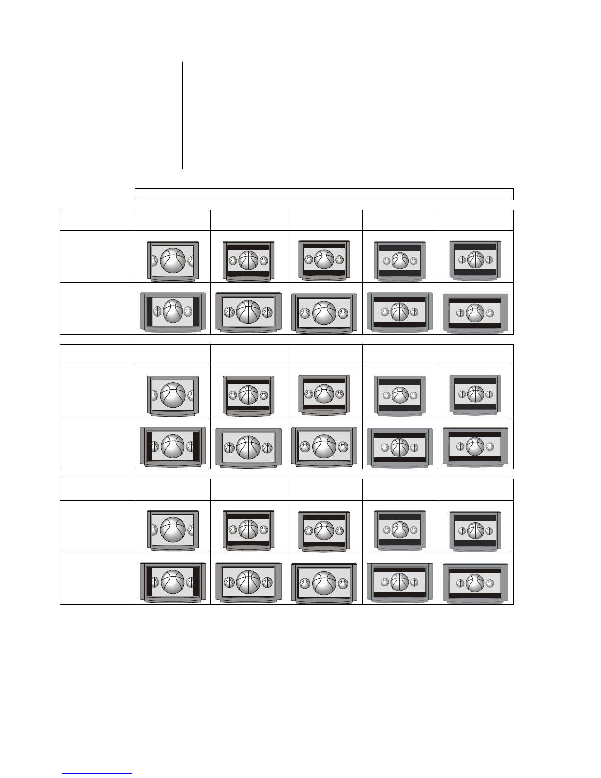
58
Aspect ratio - choosing the correct matching factor
Today’s picture sources deliver pictures with widely varying formats and aspect
ratios. In many cases the format delivered by the source device does not match
the geometry of your video monitor. The video signals coming from the source
must therefore be adjusted to suit the geometry of your monitor (4:3 or 16:9).
Different conversion factors are required for this according to the source signal
and the monitor. The table printed below is intended to help you establish the
most suitable conversion factor (no conversion, -33V, +33V, etc.) for each
combination of source signal (see ”Video signal format” columns) and monitor.
The illustrations in the table show the picture formats produced by each
combination.
Video signal format
For LCD
- or
Plasma screens
4:3 (1,33:1) 16:9 (1,85:1)
letterbox
16:9 (1,85:1)
anomorphic
21:9 (2,35:1)
letterbox
21:9 (2,35:1)
anomorphic
4:3 format
no conversion no conversion
-33 V
no conversion
-33 V
16:9 format
-33 H
+33 V
no conversion
+33 V
no conversion
4:3 projectors
4:3 (1,33:1) 16:9 (1,85:1)
Letterbox
16:9 (1,85:1)
anomorphic
21:9 (2,35:1)
Letterbox
21:9 (2,35:1)
anomorphic
With 4:3 projector screen
no conversion no conversion
-33 V
no conversion
-33 V
With 16:9 projector screen
-33 H&V
no conversion
-33 V
no conversion
-33 V
16:9
projectors
4:3 (1,33:1) 16:9 (1,85:1)
Letterbox
16:9 (1,85:1)
anomorphic
21:9 (2,35:1)
Letterbox
21:9 (2,35:1)
anomorphic
With 4:3 projector screen
-33 H
+33 V
no conversion
+33 V
no conversion
With 16:9 projector screen
-33 H
+33 V
no conversion
+33 V
no conversion
Page 59

59
Supported Audio / Video files
It is impossible to guarantee general compatibility due to the huge number of
different blank media, disc recorders (burners) and burning programs.
If you encounter compatibility problems, we recommend that you try using different blank discs and / or a different disc burner and software.
Supported video types and encoders
The K8 is capable of reproducing the following types of digital video files from a
Disc or USB memory stick connected to the front USB socket 'USB-BD'.
-
.
avi files encoded in one of the fol
lowing format combinations:
-
- video: DivX 5 720x480 @ up to 30fps 1844 kbps
DivX 5 720x576 @ up to 25fps 2014 kbps
Divx 3 640x480 @ up to 24fps, 1824 kbps
MP4 320x480 @ up to 15fps 269 kbps
Xvid 576x432 @ up to 30fps 1271 kbps
-
audio: AC3 6ch 48Khz; 448kbps max sample rate
DTS 5ch 48khz, 754kbps (DTS-ES-Matrix)
DTS 5ch 48khz, 1509kbps (DTS-ES-Discrete)
mp3 2ch 48khz 128kbps
WMA 2ch 22khz 32kbps
PCM 2ch 48khz 1536kbps
mpeg
audio 2ch 48khz 320kbps
-
.wmv files encoded in the following formats:
-
video: WMV9 up to 320x132 at 30fps
WVC1 up to 1280x720 at 24fps (5300 kbps)
-
audio: wma 2ch 48khz
-
.mkv files encoded in the following formats:
-
video: Mpeg4(h.264) 1280x720 30fps
Mpeg2 320x240 24fps
-
audio: mp3 2ch 48khz 1536kbps
dts 6ch 48khz
ac3 6ch 48khz
aac 2ch 48khz
-
.mp4 and .m4v files encoded with:
-
- video: Mpeg4(h.264) 1280x720 30fps
-
- audio: AAC 48kHz stereo 1536Kbps
-
.mpeg files encoded with:
-
- video: Mpeg1 video 640x360 25fps
-
- audio: MPEG Audio 2ch 44.1 khz 224kbps
Supported audio types and codecs
-
MP3 files (up to 44.1kHz stereo)
-
WMA files (up to 48.0kHz stereo)
-
m4a files (AAC up to 44.1kHz stereo)
Supported photo types
-
JPEG files: 4:2:2 encoded, up to 24 Mpixels
-
JPEG files: 4:4:4 encoded, up to 12 Mpixels
-
PNG files: up to 12 Mpixels
Page 60

60
Notes on Energy Saving
The K8 fulfils the requirements of the latest directives designed to economise
on the use of energy (EuP directive). The modern construction of its mains PSU
and the highly efficient design of the T+A switch-mode output stage play an important role in this.
The internal micro-processor constantly ensures that sub-assemblies which are
not required for the current task are switched off automatically.
In stand-by mode the current drain depends on the functions of the K8 which
are still active. Please refer to the table below for more details.
ECO stand
-by
Comfort stand
-by
Screen brightness
Screen off Screen brightness = min. Screen brightness = max.
Functions available in s
tand
-
by mode
* Alarm timer
* Can be switched on
using remote control
* Alarm timer
* Can be switched on by remote control
* iPod battery charging
*
Ethernet switch + HDMI HEC function
* Clock display
* Automatic clock setting (VHF-RDS)
* Sleep timer
Stand
-
by current drain
0.4 W < 3 W up to 6 W
for charging iPod
< 4 W up to 6 W
for charging iPod
In accordance with EU regulations designed to limit stand-by consumption, the
default factory setting for the K8 is the ECO stand-by mode.
If you wish to use the additional functions of the Comfort stand-by mode (On),
you must switch it on in the menu System Configuration / Stand.by-mode.
Switching off unused
output stages
Audio output stages consume energy even when no loudspeaker is connected
to them and no signal is present. The K8 offers the facility to save energy by
switching off output stages not currently required. This is accomplished by
calling up the menu System configuration / Source names and switching
“Disable” all output stages which are not needed for loudspeakers in the main
room or adjacent rooms.
This measure also reduces the heat developed by the K8.
Page 61

61
Anhang
Appendix
Page 62
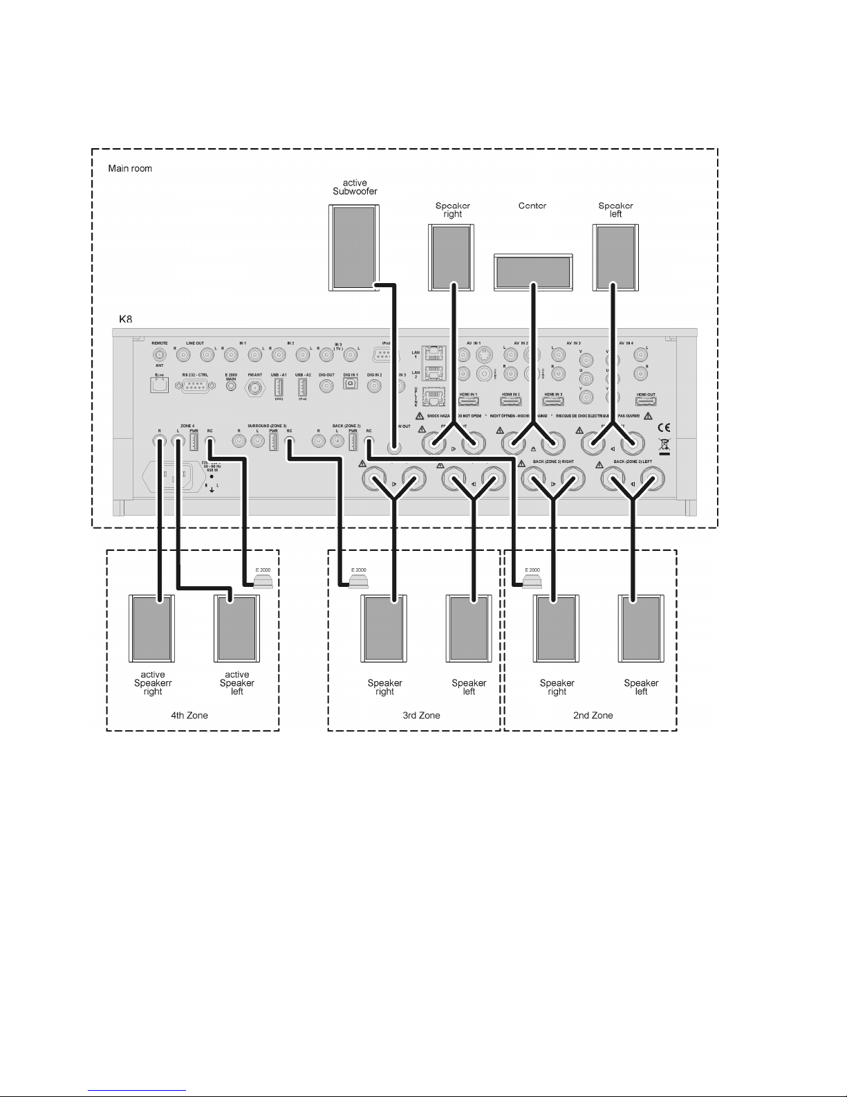
62
Appendix A
Wiring diagram: Main room 3.1 loudspeaker wiring, additional listening zone 2, 3 and 4
Page 63
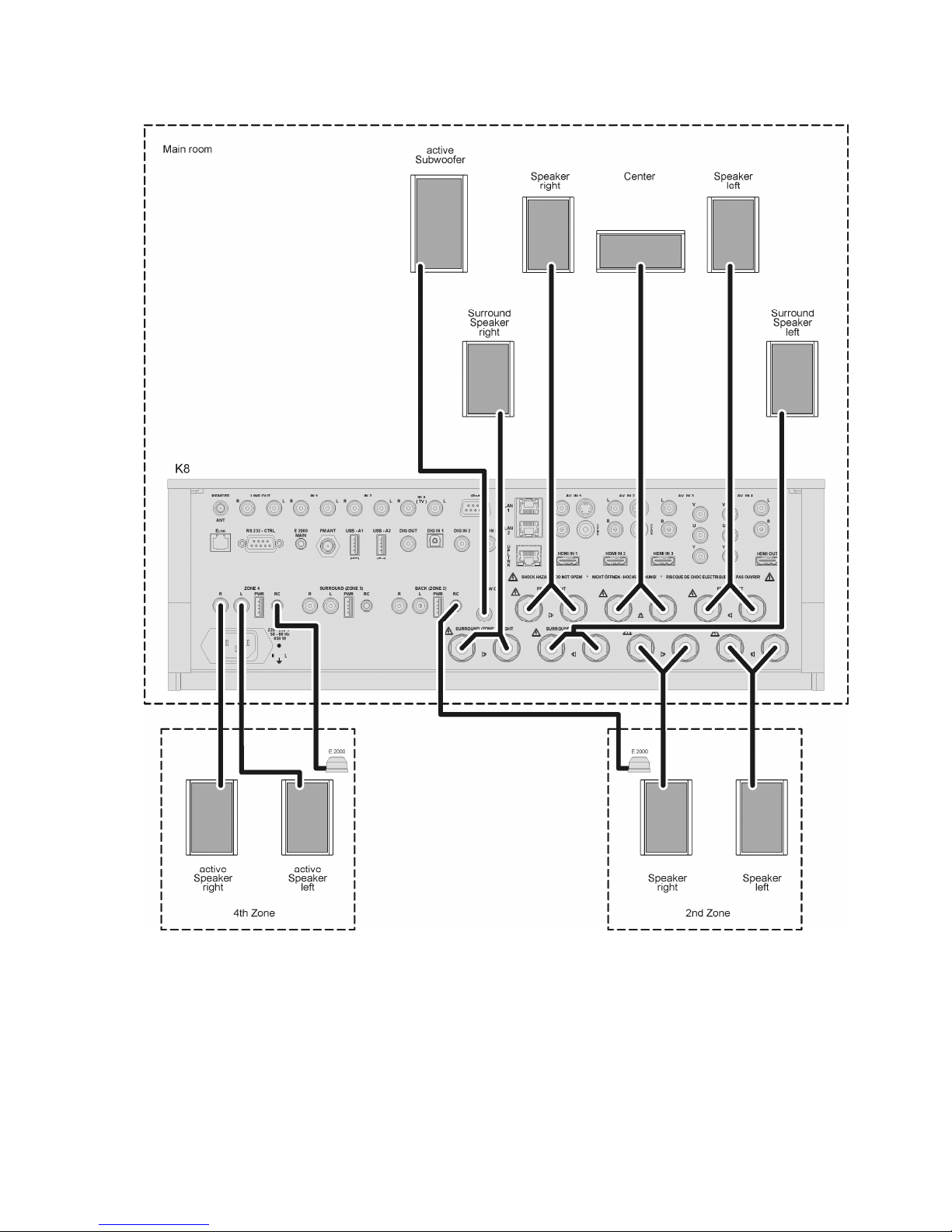
63
Wiring diagram: Main room 5.1 loudspeaker wiring, additional listening zone 2 and 4
Page 64
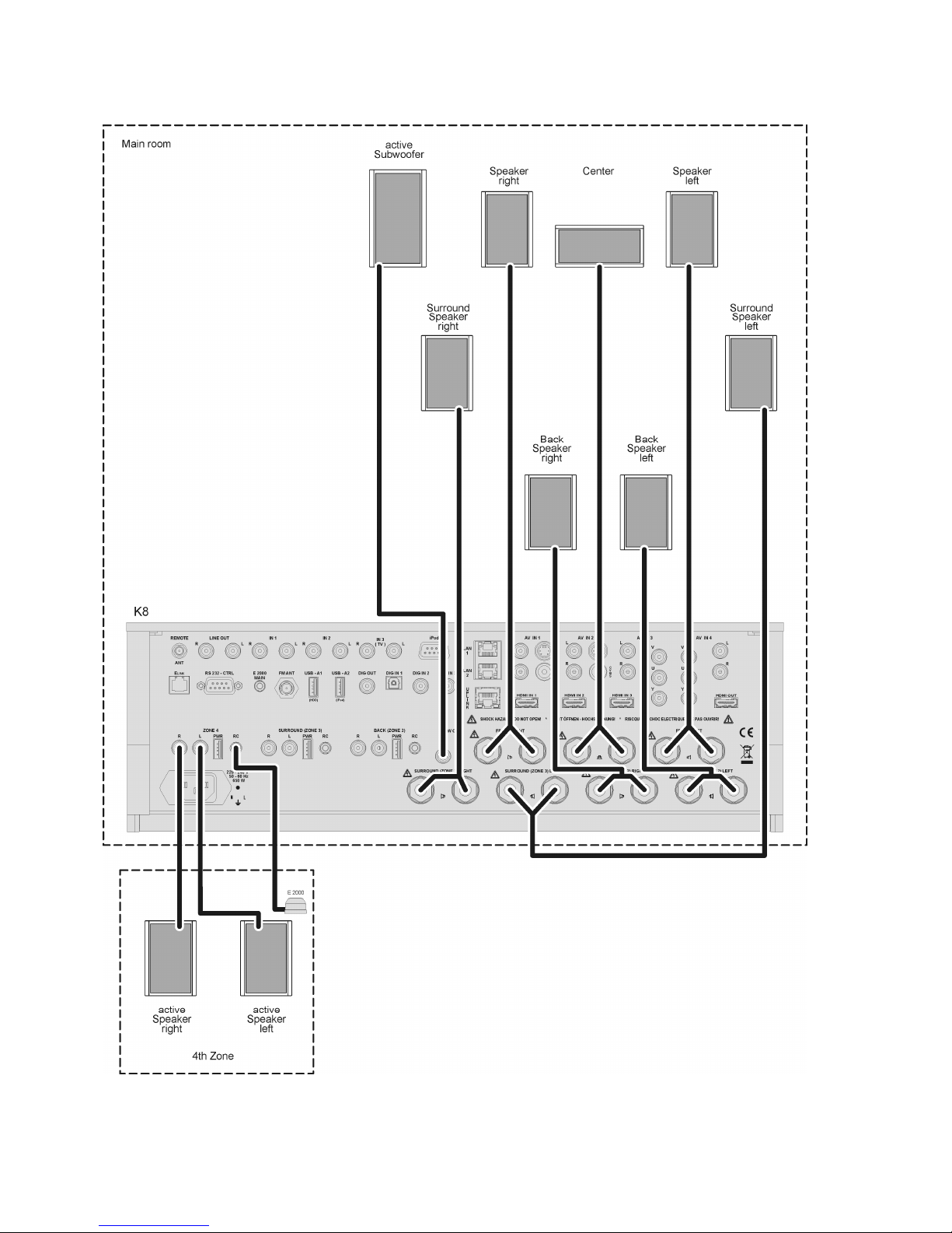
64
Wiring diagram: Main room 7.1 loudspeaker wiring, additional listening zone 4
Page 65
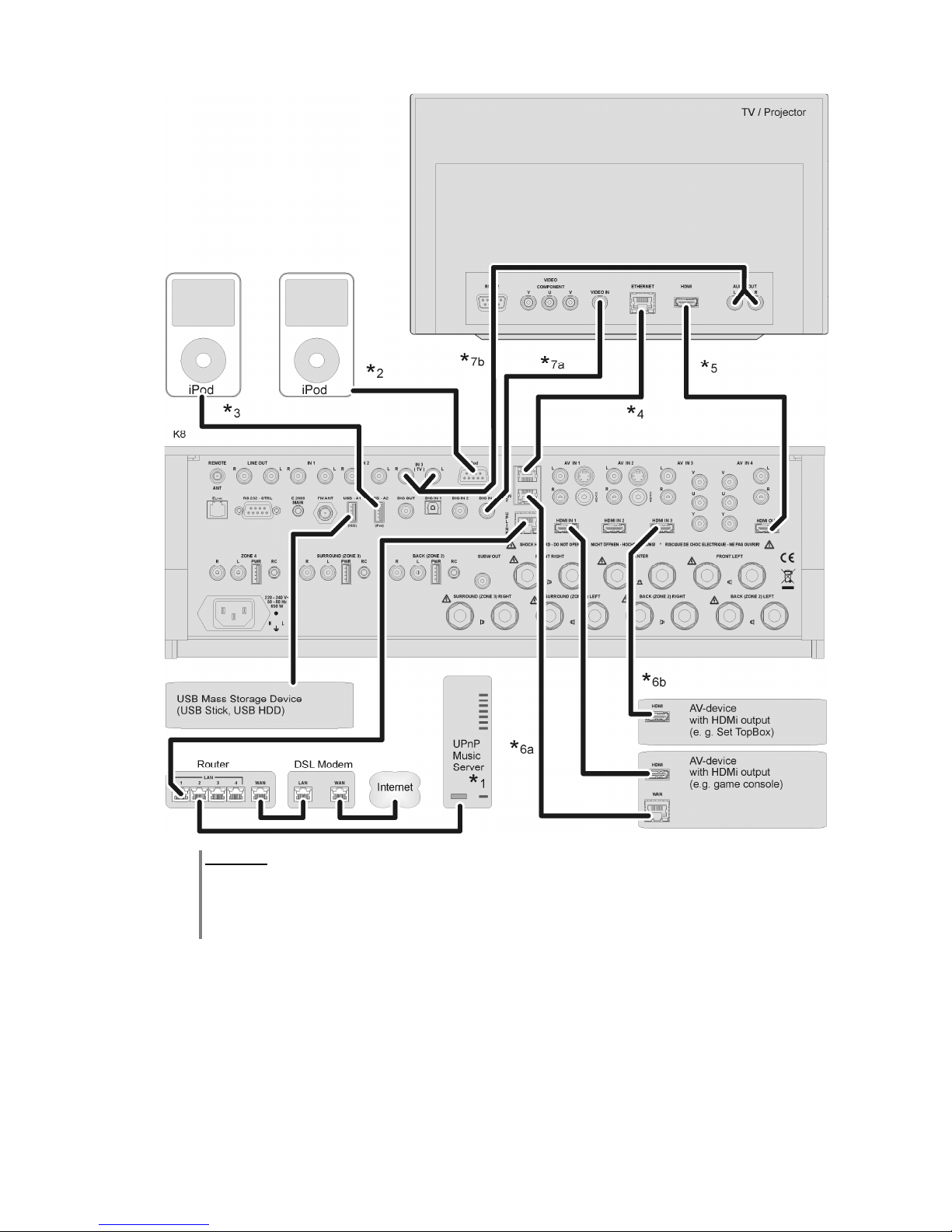
65
Wiring diagram: TV, iPod, HDMI and network wiring
Attention!
A properly set up home network with router must be installed and in operation to use the K8.
For the use of internet radio a DSL access to the internet is needed.
For questions regarding setting up your network and internet connection please ask your system
administrator or any network specialist.
*1 Music Server with UPnP-AV server software installed
*2 If you need iPod video, use the 15-pin analogue iPod socket on the K8.
*3 Digital iPod connection (for audio playback only)
*4 If the TV set features a network connection (Internet), it can be connected to the network via the K8.
Connect the Ethernet output of the TV set to the LAN output of the K8 and carry out the appropriate
configuration.
*5 HDMI TV connection with Ethernet over HDMI (HEC) and Audio Return Channel (ARC)
*6a Connection of a network-capable source device to the K8’s network switch using a LAN lead
*6b for connection HDMI IN 3: Connection of a network-capable source device to the K8’s network switch via
Ethernet over HDMI (HEC).
*7 Audio connection TV K8 (if TV sound is to be reproduced via the K8). Connection either digital (7a) or
analogue (7b). Please assign the “TV” input appropriately using the System settings / Audio inputs
menu.
Page 66
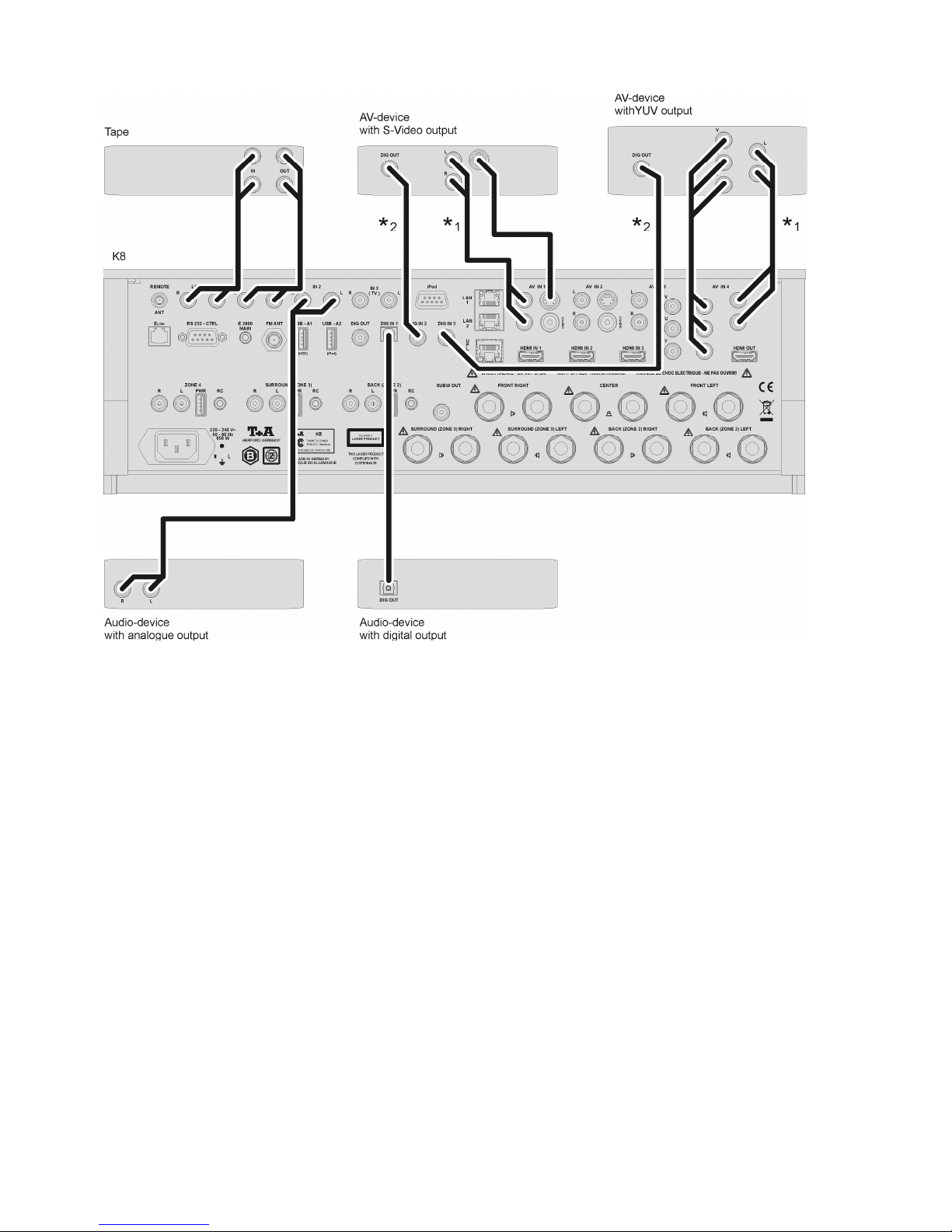
66
Wiring diagram: AUDIO-Video-connection
*1 If the TV set features an analogue audio output, connect it to the Audio input.
Please enter the appropriate settings in the Audio Inputs menu.
*2 If the TV set features a digital audio output, connect it to one of the digital sound inputs.
Please enter the appropriate settings in the Audio Inputs menu.
*3 Devices with an S-Video output should be connected to the S-Video socket of the AV IN input.
Please enter the appropriate settings in the Video Inputs menu.
Page 67

Appendix B
BluR
ay Player
Drive
3-laser BluRay linear drive on vibration dampening subchassis
Playable media Video
Photo
Audio
Container + other formats
BluRay Disc, DVD, VCD, SVCD
JPEG, Picture Disc
CDDA (Audio CD), MP3 CD, CD-R, CD/RW, Hybrid SACD CD Layer
MKV, MPG, AVI, VOB, MP4, WMV
other features BD-Live (with external USB memory stick)
Movie mode 1080p/24 Hz,
extended colour space (xvYCC)
Streaming Client
Formats MP3, WAV, FLAC, AAC, OGG-Vorbis, WMA (WMDRM 10)
Bit rates all formats
other bit rates WAV, FLAC
8 … 48 kSps/16Bit, variable bit rate (VBR)
96 kSps / 24Bit
Media server, Network memory (PC, NAS) UPnP AV + DLNA compatible streaming servers
Web radio Web radio with vTuner internet radio service
Interfaces LAN
USB
Ethernet 10/100 Mbit
1x USB 2.0 for memory stick or harddisc drive (HDD)
1x USB 2.0 for iPod or 2nd memory stick / HDD
other features Favourite lists, station memory for web radio stations
Digital iPod audio playback
Charging function for iPod
i
Pod-AV
interface
Playback of audio and video files from iPod incl. iPod navigation and
remote control
FM-Tuner
HE bandwidth 87,5 – 108 MHz
Sensitivity 2 2V
Strong signal immunity > 125 dB
Stereo crosstalk suppression > 40 dB
RDS functions Station name, Program type, Radio text, Time
other features Presets
Video
Processor
HDMI inputs
Features
3 x HDMI 1.4
HDMI Ethernet Channel (HEC) on HDMI IN 3
Analogue A/V inputs 2 x YUV
2x Video Composite (FBAS) or S-Video
HDMI output
Features
HDMI 1.4
Audio return channel (ARC)
HDMI Ethernet Channel (HEC)
Functions
A/D conversion
Scaling
Picture adjustment
Conversion of analogue AV signals to HDMI
All digital (HDMI) or analogue AV input signals to 576, 720, 1080
interlaced or progressive output format
Colour, contrast, sharpness, aspect ratio, overscan, zoom
other features Scaler bypass
3D pass through (3D ready)
Auto mode (automatic image size adaptation to monitor)
Page 68

Surround
decoder
Type 7.1 HighDefinition (HD) surround decoder with 2 freely programmable
56 Bit dual core signal processors (DC DSP)
Formats Stereo
Dolby Pro Logic IIx, Dolby Digital (AC3), Dolby EX, Dolby Digital Plus,
Dolby TrueHD
dts, dts-96/24, NEO:6, dts-ES, dts-ES discrete, dts-HighResolution,
dts-HD Master Audio
Loudspeaker configurations 2.0, 2.1, 3.0, 3.1, 4.0, 4.1, 5.0, 5.1, 7.0, 7.1
other features Dolby Volume
Dolby Headphone
Downmix function for line out and stereo sound for side rooms
Automatic calibration function for loudspeakers
Preamplifier
/ DA
Converter
Audio inputs (analogue)
3 x stereo line input 2 V / 20 kΩ
4 x stereo input 2 V / 20 kΩ
(as part of the analogue AV inputs)
Audio inputs (digital)
2x SP/DIF coax Stereo up to 192 kSps / 24 Bit
Dolby + dts surround formats (IEC 1937)
1x SP/DIF optisch Stereo up to 96 kSps / 24 Bit
Dolby + dts surround formats (IEC 1937)
Audio outputs analogue Fixed level
Variable
(with volume control)
1x stereo line out 2 V, 200 ohms e. g. for tape recorder
1x subwoofer 2 V, 100 ohms
1x stereo out e. g. for acoustic supply of side rooms
1x stereo out for active surround speakers or side room
1x stereo out for active rear speakers or side room
other features 3 audio outputs with 5 V power supply e.g. for wireless audio
transmission modules, remote turn-on of active loudspeakers etc.
Audio output digital 1x SP/DIF coax
D/A conversion High-class 24 Bit / 192 kSps Burr-Brown D/A converters for all 7.1
channels
Dual-converter differential DAC for the front channels L/R
Volume control Loss-free, high-precision volume regulation with professional studio-
grade volume controls
Frequency response 2 Hz - 60 kHz
(1)
2 Hz - 44 kHz
(2)
2 Hz - 22 kHz
(3)
THD / Intermodulation < 0.002 % / <0.004%
(1), (2) / (3)
S/N ratio 110 dB (1), (2), (3)
Effective system dynamic 110 dB / 98 dB (1), (2) / (3)
Channel separation 100 dB (1), (2), (3)
(1) SP/DIF 192/24 Digital_In or HD-BluRay
(2) SP/DIF 96/24 Digital_In or 96/24 HD Streaming
(3) SP/DIF 48/16 Digital_In or 48/16 Streaming
each measured on the stereo preamp outputs
Headphone output
for dynamic headphones > 30 Ω, with automatic speaker muting and
Dolby-Headphone
Power Amplifiers
7 high performance switching power modules ( Linear-PWM
design)
Nominal output power / ch. (Stereo) 8 Ω / 4 Ω 95 W / 150 W
Transient output power 8 Ω / 4 Ω 130 W / 230 W
Distortion (THD) < 0,005 %
Intermodulation < 0,005 %
Frequency response 1 Hz – 60 kHz
Page 69

Additional Features
Wake-up timer, iPod charging function
Ethernet-switch
distribution of an Ethernet uplink connection to
BluRay player,
streaming-client
TV monitor (via HDMI / HEC),
up to 3 HDMI source devices (via HDMI / HEC)
up to 2 more external devices (via LAN cable) (e.g. playing console)
RS 232 control interface for controlling suitably equipped Metz or Loewe TV sets
General
Mains conn
ection
:
EU version: 220-230 V / 50 - 60 Hz
US version 110-117 V / 50 - 60 Hz
Power consumption
max. 650 W
Eco standby 0,4 W active functions: IR remote control,
wake-up timer,
Comfort standby 3 - 4 W (depending on dispay brightness)
supplementary active functions: Ethernet router
iPod charging
The set includes:
FM100 remote control handset, mains lead, HDMI lead, iPod lead,
network lead, FM aerial, calibration microphone,
E2000 external remote control receiver,
operating instructions, guarantee request card
Optional accessories:
FD100 bidirectional wireless remote control with display
(FBS FD100- K8)
E 2000 external remote control receiver
iPod docking station
Order no. 4362 49301 for digital USB connection
Order no. 4362 49201 for analogue iPod connection
We reserve the right to introduce technically-founded modifications.
Page 70

elektroakustik GmbH & Co. KG
Herford
Deutschland * Germany
 Loading...