

Page 1

BETRIEBSANLEITUNG
USER MANUAL
G 1260 R
V 1.0 Bestellnr. / Order No. 9103-0425 DE/UK
Page 2

2
Page 3

Seite / Page
Deutsch
English
............................................................................................................. 4
.............................................................................................................. 22
Anhang / Appendix:
Technische Daten / Technical specifications
.......... 39
3
Page 4

Willkommen.
Wir freuen uns, dass Sie sich für ein -Produkt entschieden haben. Mit Ihrem neuen Plattenspieler G 1260 R haben
Sie ein HiFi-Gerät der Spitzenklasse erworben, bei dessen Konzeption und Entwicklung den Wünschen des audiophilen
Musikliebhabers oberste Priorität eingeräumt wurde.
Die innovativen Problemlösungen, die solide, durchdachte Konstruktion und die verwendeten hochwertigen Materialien
werden dazu beitragen, dass dieses Gerät höchsten Anforderungen und Ansprüchen über viele Jahre genügen wird.
Eine genaue Qualitätsprüfung aller Materialien, die sorgfältige Produktion durch hochqualifizierte Fachkräfte und eine
rechnergesteuerte, vollautomatisierte Endkontrolle gewährleisten die hohe Produktqualität und die Einhaltung aller
Spezifikationen.
In unserer Geräteproduktion wird der Einsatz aller umwelt- und gesundheitsgefährdenden Stoffe, wie z. B. chlorhaltige
Lösungsmittel und FCKWs, vermieden.
Darüber hinaus verzichten wir wo irgend möglich auf Kunststoffe (insbesondere auf PVC) als Konstruktionselement.
Statt dessen wird auf Metalle oder andere unbedenkliche Materialien zurückgegriffen, die einerseits gut recyclebar sind
und andererseits eine sehr gute elektrische Abschirmung ergeben.
Durch unsere massiven Ganzmetallgehäuse wird eine Beeinträchtigung der Wiedergabequalität durch äußere Störquellen ausgeschlossen. Dadurch wird sichergestellt, dass die von den Geräten ausgehende elektromagnetische
Strahlung (Elektrosmog) gut abgeschirmt und auf ein absolutes Minimum reduziert wird.
Als Sonderzubehör sind hochwertige Kabel und Steckverbinder sowie auf das Gerätedesign abgestimmte Tonmöbel
lieferbar.
Wir bedanken uns für Ihr Vertrauen und wünschen Ihnen viel Freude und Hörvergnügen mit Ihrem Plattenspieler.
elektroakustik GmbH & Co KG
Alle verwendeten Bauteile entsprechen den geltenden deutschen und europäischen Sicherheitsnormen und
Dieses Produkt entspricht den Niederspannungsrichtlinien (73/23/EEC), EMV-Richtlinien (89/336/EEC, 92/31/EEC)
und den CE-Markierungsrichtlinien (93/68/EEC).
-standards. Zu Ihrer eigenen Sicherheit sollten Sie bitte unbedingt diese Betriebsanleitung vollständig lesen
und insbesondere die Aufstellungs-, Betriebs- und Sicherheitshinweise genau befolgen.
4
Page 5

Inhaltsverzeichnis
Bedienung
Bedienelemente der Frontseite ....................................................................................... 6
Abspielen einer Schallplatte ............................................................................................ 6
Anschluss und Inbetriebnahme
Anschlusselemente an der Rückseite ............................................................................ 8
Aufstellung und Verkabelung .......................................................................................... 9
Montage des Plattentellers ............................................................................................ 11
Montage des Gegengewichts und Kontrolle der Tonarmeinstellung ............................. 13
Einbau und Ausrichtung eines Tonabnehmersystems .................................................. 14
Sicherheitshinweise ....................................................................................................... 15
Der G 1260 R PHONO Vorverstärker (optional) ........................................................... 17
Einstellungen der Codierschalter ................................................................................... 18
Betriebsstörungen ......................................................................................................... 19
Anhang
Technische Daten .......................................................................................................... 39
5
Page 6
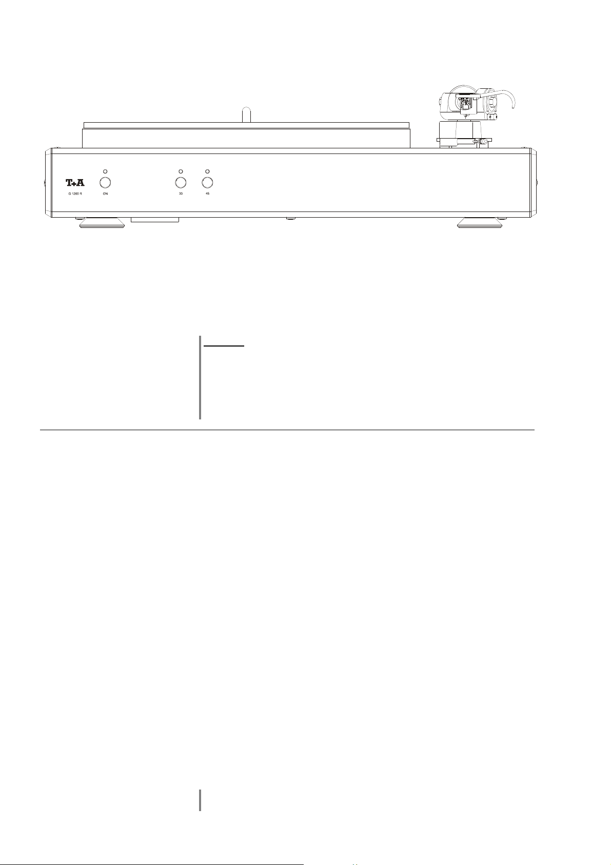
Bedienelemente der Frontseite
33 / 45
(Ein- und Ausschalter)
Kurzes Antippen des
geschaltetem Gerät leuchtet die LED über dem Taster.
Bei Betrieb in Verbindung mit einer R-Anlage schaltet sich der G 1260 R über
die bestehende R
„AUX2“) als Hörquelle gewählt wird. Beim Ausschalten der R-Anlage schaltet
sich der G 1260 R automatisch aus.
Achtung!
Der Netztaster ist kein Netztrenner. Auch wenn die Leuchtdiode
ausgeschaltet ist, sind Teile des Gerätes mit der Netzspannung
verbunden (Standby-Betrieb). Die Standby-Stromaufnahme ist im Kapitel
„Technischen Daten“ angegeben.
Soll das Gerät längere Zeit nicht benutzt werden, ist es vorteilhaft, den
Netzstecker zu ziehen.
Taster zur Wahl der Drehgeschwindigkeit
Bei stehendem Plattenteller startet ein Druck auf einen der Taster den
Tellermotor mit der über dem Taster angegebenen Drehgeschwindigkeit.
Während des Hochlaufens des Motors blinkt die LED über dem Taster. Sobald
die Sollgeschwindigkeit erreicht ist leuchtet die LED dauerhaft.
Zum Umschalten der Geschwindikeit tippen Sie einfach auf den anderen der
beiden Taster.
Stoppen des Tellermotors
Tippen Sie bei drehendem Plattenteller den Taster unter der leuchtenden LED
an, so wird der Plattenteller aktiv gebremst und kommt nach kurzer Zeit zum
Stillstand.
-Tasters schaltet das Gerät ein und aus. Bei ein-
Link
-Verbindung ein, sobald ein Phonoeingang („AUX1“ oder
Abspielen einer Schallplatte
Bedienung
• Schalten Sie das Gerät durch kurzes Antippen des
• Legen Sie die Schallplatte auf den Plattenteller.
• Vor jedem Abspiel empfehlen wir, den Oberflächenstaub auf der Platte
z. B. mit Hilfe einer Kohlfaserbürste oder eines Antistatiktuches zu
entfernen.
• Drücken Sie den 33 oder 45 UpM Taster (entsprechend der aufgelegten
Schallplatte), um den Motor zu starten.
• Schwenken Sie den Tonarm nach innen über die gewünschte Rille.
Leuchtet die LED über dem gedrückten Taster dauerhaft, ist die
Solldrehzahl erreicht und der Tonarm kann durch Betätigen des
Tonarmlifthebels (siehe Abbildung 'Einstellelemente des Tonarms',
Kapitel 'Montage des Gegengewichts und Kontrolle der
Tonarmeinstellungen') langsam abgesenkt werden.
Die optional erhältliche Haube muss zum Betrieb des G 1260 R entfernt
werden.
6
Tasters ein.
Page 7

Installation
Inbetriebnahme
Sicherheitshinweise
In diesem Kapitel werden alle Dinge von grundsätzlicher Bedeutung für die Aufstellung und Inbetriebnahme beschrieben, die nicht für den täglichen Umgang mit dem Gerät relevant sind, die aber trotzdem vor dem ersten Gebrauch gelesen und beachtet werden sollten.
7
Page 8
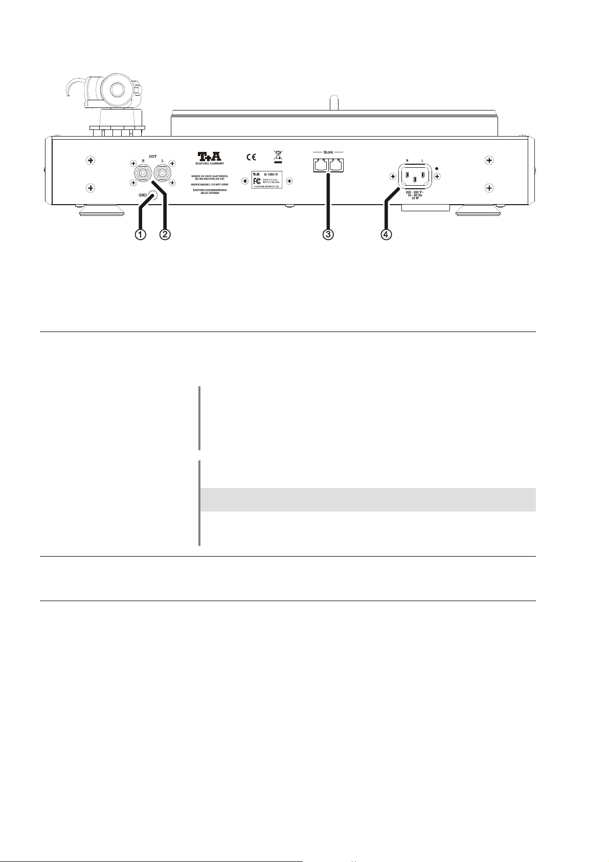
Anschlusselemente
GND
OUT
Erdungsklemme
Nur für G 1260 R Version ohne eingebautes Phonomodul:
Verbinden Sie diesen Anschluss mit der Erdungsklemme an Ihrem Verstärker.
Bei G 1260 R mit Phonomodul bleibt diese Klemme unbenutzt.
Ausgangsbuchsen
Bei G 1260 R Versionen ohne eingebautes PHONO Vorverstärkermodul:
Verbinden Sie diese Buchsen mit einem PHONO-Eingang Ihres Verstärkers
Bitte beachten Sie, dass wenn im G 1260 R kein Phonomodul eingebaut ist,
dieses im Verstärker / Receiver vorhanden sein muss.
Bei im G 1260 R eingebautem PHONO Vorverstärkermodul:
Verbinden Sie diese Buchsen mit einem Hochpegeleingang (Line-Eingang)
Ihres Verstärkers.
Verwenden Sie je nach Verstärkermodell einen der folgenden Eingänge zum
Anschluss des G 1260 R:
Eingang Gerät
AUX 2
AUX1
P1230/1260R, PA1230/1260R, PA1530R, R1530 R
R1230R
R
LINK
Netzeingang
Steuereingang zum Anschluss an Geräte mit R
Verstärker PA 1260 R).
Diese Buchse dient dem Netzanschluss.
8
LINK
-Steuerung (z. B. an den
Page 9

Aufstellung und Verkabelung
Packen Sie den G 1260 R vorsichtig aus und heben Sie die Originalverpackung
sorgfältig auf. Der Karton und das Verpackungsmaterial sind speziell für dieses
Gerät konzipiert und bei späteren Transporten ein sicherer Behälter.
Bitte beachten Sie unbedingt die Sicherheitshinweise dieser Anleitung.
War das Gerät größerer Kälte ausgesetzt (z. B. beim Transport), so ist mit der
Inbetriebnahme zu warten, bis sich das Gerät auf Raumtemperatur aufgewärmt
hat und das Kondenswasser restlos verdunstet ist.
Vor der Aufstellung des Gerätes auf empfindlichen Flächen sollte ggf. an einer
nicht sichtbaren Stelle die Verträglichkeit des Lackes mit den Gerätefüßen
überprüft werden.
Das Gerät ist waagerecht auf einer festen, ebenen und nicht schwingenden
Unterlage aufzustellen. Die Füße sind mit Schwingmetallen entkoppelt und
dadurch beweglich. Bei Aufstellung auf Resonanzdämpfern oder Entkopplungsgliedern ist darauf zu achten, dass die Standsicherheit des Gerätes nicht beeinträchtigt wird.
Die Aufstellung darf nur an einem gut belüfteten, trockenen Ort erfolgen, wobei
direkte Sonneneinstrahlung und die Nähe von Heizkörpern zu vermeiden sind.
Das Gerät darf nicht in der Nähe von wärmeproduzierenden, wärmeempfindlichen oder leicht brennbaren Gegenständen bzw. Geräten aufgestellt
werden.
Sorgen Sie beim Einbau in Regale oder Schränke deshalb unbedingt für
ausreichende Luftzufuhr und sorgen Sie dafür, dass die Wärme des Gerätes
abgeführt werden kann. Ein Wärmestau beeinträchtigt die Lebensdauer des
Gerätes und ist eine Gefahrenquelle.
Verlegen Sie Netz- oder Lautsprecher- und Fernbedienungskabel möglichst
entfernt von Ton- und Antennenleitungen und keinesfalls über oder unter dem
Gerät.
Hinweise zum Anschluss:
• Stecken Sie alle Stecker fest in die Buchsen ein. Lockere Steckverbindungen
können Brummen oder andere Störgeräusche verursachen.
• Zur Erreichung des maximalen Störabstandes sollte der Netzstecker so in die
Netzsteckdose gesteckt werden, dass die Phase an dem Kontakt der Netzeingangsbuchse angeschlossen wird, der mit einem Punkt ()
gekennzeichnet ist. Die Phase der Netzsteckdose kann mit einem dafür
geeigneten Messgerät ermittelt werden. Wenden Sie sich bitte an Ihren
Fachhändler.
• Wir empfehlen die Verwendung der konfektionierten –Netzkabel
'POWER LINE' in Kombination mit der Netzsteckdosenleiste 'POWER BAR',
die mit Phasenindikator ausgestattet ist.
• Nachdem die Anlage vollständig verkabelt ist, stellen Sie bitte den
Lautstärkeregler auf eine sehr geringe Lautstärke und schalten Sie die
Anlage ein.
Falls bei der Inbetriebnahme des Gerätes Probleme auftreten sollten, haben
diese oftmals einfache Ursachen, die leicht zu beheben sind. Lesen Sie dazu
das Kapitel 'Betriebsstörungen' dieser Betriebsanleitung.
9
Page 10

Lautsprecher- und
Signalkabel
Die verwendeten Lautsprecher- und Signalkabel haben einen nicht zu
unterschätzenden Einfluss auf die Wiedergabequalität der Gesamtanlage.
empfiehlt daher die Verwendung hochwertiger Kabel und Steckverbinder.
In unserem Zubehörprogramm finden Sie eine Reihe exzellenter Kabel und
Stecker, die in ihren Eigenschaften auf unsere Lautsprecher und
Elektronikkomponenten abgestimmt sind und hervorragend mit diesen
harmonieren. Für schwierige und beengte Aufstellungsbedingungen finden Sie
im Zubehör auch Kabel in Sonderlängen und Sonderstecker (z. B. in
abgewinkelter Form), mit deren Hilfe sich fast jedes Anschluss- und
Aufstellungsproblem lösen lässt.
Netzkabel und Netzfilter
Mechanische
Entkopplung
Über die Netzstromversorgung gelangt nicht nur die notwendige
Betriebsenergie zu Ihren Geräten, sondern oft auch Störungen von entfernten
Geräten, Funk- und Computeranlagen.
Um elektromagnetische Störungen von den Geräten fern zu halten, bietet
unser Zubehörprogramm das speziell abgeschirmte Netzkabel 'POWER
FOUR', das konfektionierte Netzkabel mit Mantelkernfiltern 'POWER LINE' und
die Netzfilterleiste 'POWER BAR'. Mit diesem Zubehör kann die
Wiedergabequalität unserer Geräte in vielen Fällen nochmals gesteigert
werden.
Zu allen Fragen rund um die Verkabelung berät Sie gern Ihr Fachhändler
kompetent, umfassend und unverbindlich. Gern senden wir Ihnen auch unser
umfangreiches Informationsmaterial zu diesem Thema.
Die Standfläche und der Untergrund, auf dem hochwertige HiFi-Geräte
aufgestellt werden, haben einen nicht zu unterschätzenden Einfluss auf die
erreichbare Klangqualität. Die Standfläche sollte möglichst schwer, stabil, hart
und eben sein.
Das Gerät ist mit den neuentwickelten Vibrationsabsorberfüßen
ausgestattet. Diese Füße erreichen durch ihre inneren
Dämpfungseigenschaften eine sehr gute Entkopplung des Gerätes vom
Untergrund. Hierdurch werden Vibrationen des Untergrundes aufgefangen und
das Tonabnehmersystem wird vor Mikrophoniestörungen geschützt.
Damit die Vibrationsabsorber einwandfrei funktionieren können, sollte
das Gerät frei aufgestellt werden. Ein Kontakt des Gehäuses mit Wänden
usw. sollte vermieden werden.
Pflege des Gerätes
Vor Reinigungsarbeiten am Gerät ist der Netzstecker zu ziehen.
Die Oberflächen des Gerätes sollten zur Reinigung nur mit einem
angefeuchtete weichen Tuch oder Schwamm abgewischt werden. Nicht trocken
abreiben. Zum Anfeuchten des Tuches verwenden Sie bitte ausschließlich
Wasser ggf. mit etwas mildem Reinigungsmittel wie z. B. Neutralreiniger,
Schmierseife oder ähnlichem. Verwenden Sie niemals organische
Lösungsmittel, die z. B. Verdünnung, Alkohol oder Kraftstoffe enthalten
können.
Vor der Wiederinbetriebnahme muss sichergestellt sein, dass keine
Kurzschlüsse an den Anschlussstellen bestehen und dass alle Anschlüsse
ordnungsgemäß sind.
10
Page 11
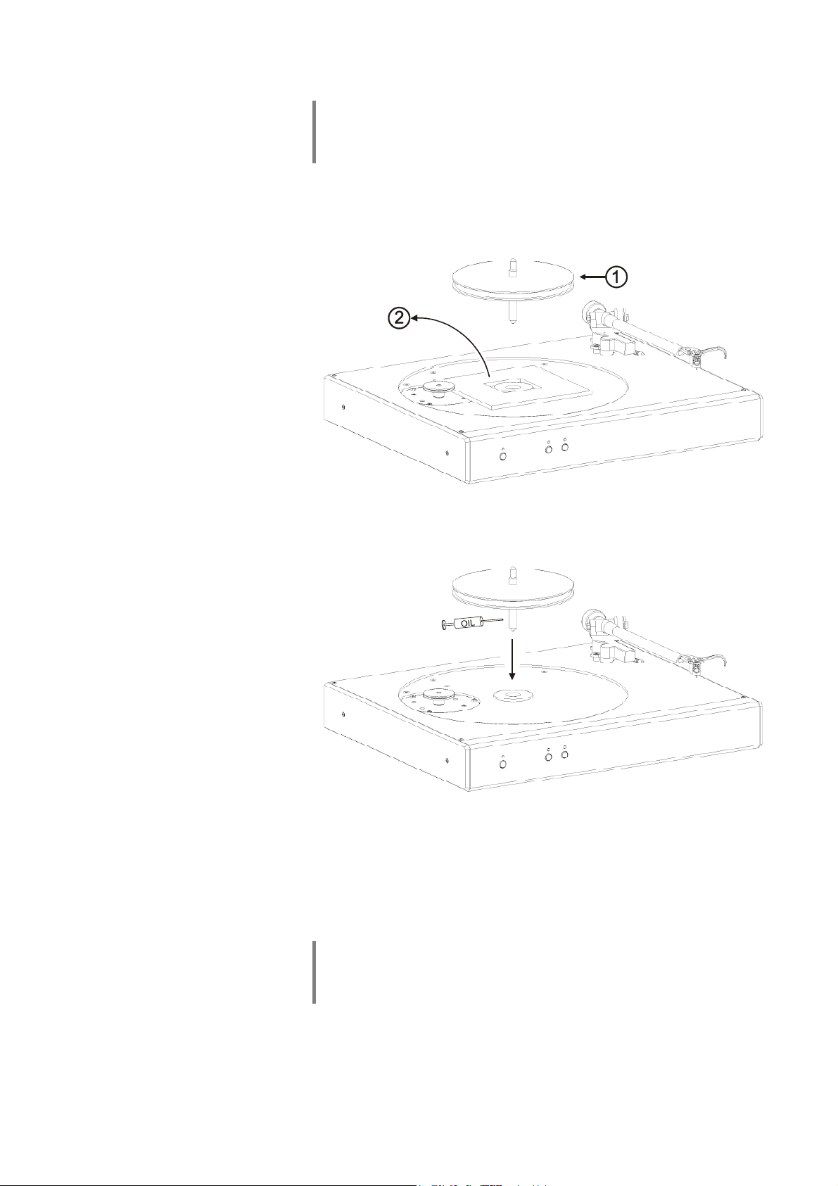
Montage des Plattentellers
Wichtiger Hinweis für die folgenden Montageschritte:
Bitte vermeiden Sie unbedingt, dass Öl auf den Treibriemen oder die
Riemenscheibe gelangt!
Achten Sie darauf, dass kein Schmutz in das Tellerlager gelangt.
1. Ziehen Sie die Riemenscheibe () mitsamt der Plattentellerachse aus dem
Tellerlager.
2. Entfernen Sie die Transportsicherung ().
3. Ölen Sie die Plattentellerachse / Lagerbuchse im Plattenteller mit der
beigefügten Ölspritze gut ein.
4. Setzen Sie die Plattentellerachse unter leichtem Drehen mit leichtem
Druck wieder in die Lagerbuchse ein. Dabei beachten Sie bitte, dass sich
die Achse im Lager nicht verkantet. Die Achse muss leicht in das Lager
gleiten.
5. Drücken Sie die Riemenscheibe so weit wie möglich nach unten. Die
Riemenscheibe sinkt langsam auf der Lagerachse nach unten. Warten
Sie, bis er auf der Lagerspitze aufliegt.
Hinweis:
Aufgrund des extrem geringen Lagerspiels kann es einige Zeit dauern, bis alle
Luft aus dem Lager entwichen ist und sich die Achse ganz im Lager gesetzt
hat. Dieser Vorgang kann einige Zeit in Anspruch nehmen (bis zu 30 Min.).
11
Page 12
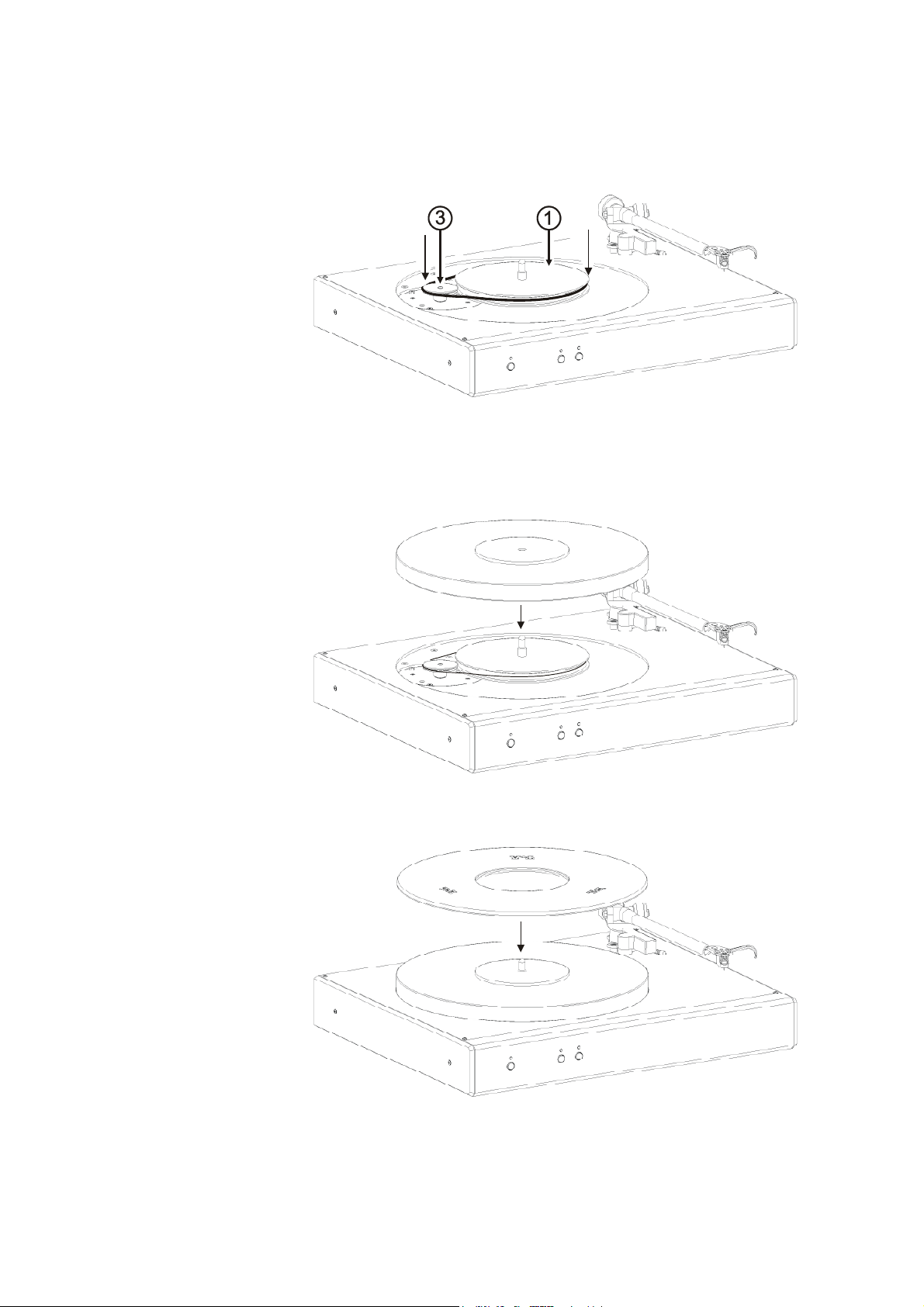
6. Wenn die Riemenscheibe ihre Endlage erreicht hat, kontrollieren Sie bitte,
ob sich die Scheibe leicht von Hand drehen lässt.
7. Legen Sie den Treibriemen wie in der Abbildung gezeigt um das
Tellerantriebsrad () und die Riemenscheibe ().
8. Setzen Sie den Plattenteller vorsichtig und senkrecht auf die Lagerachse
auf.
9. Legen Sie nun die Gummimatte auf den Plattenteller auf.
12
Page 13
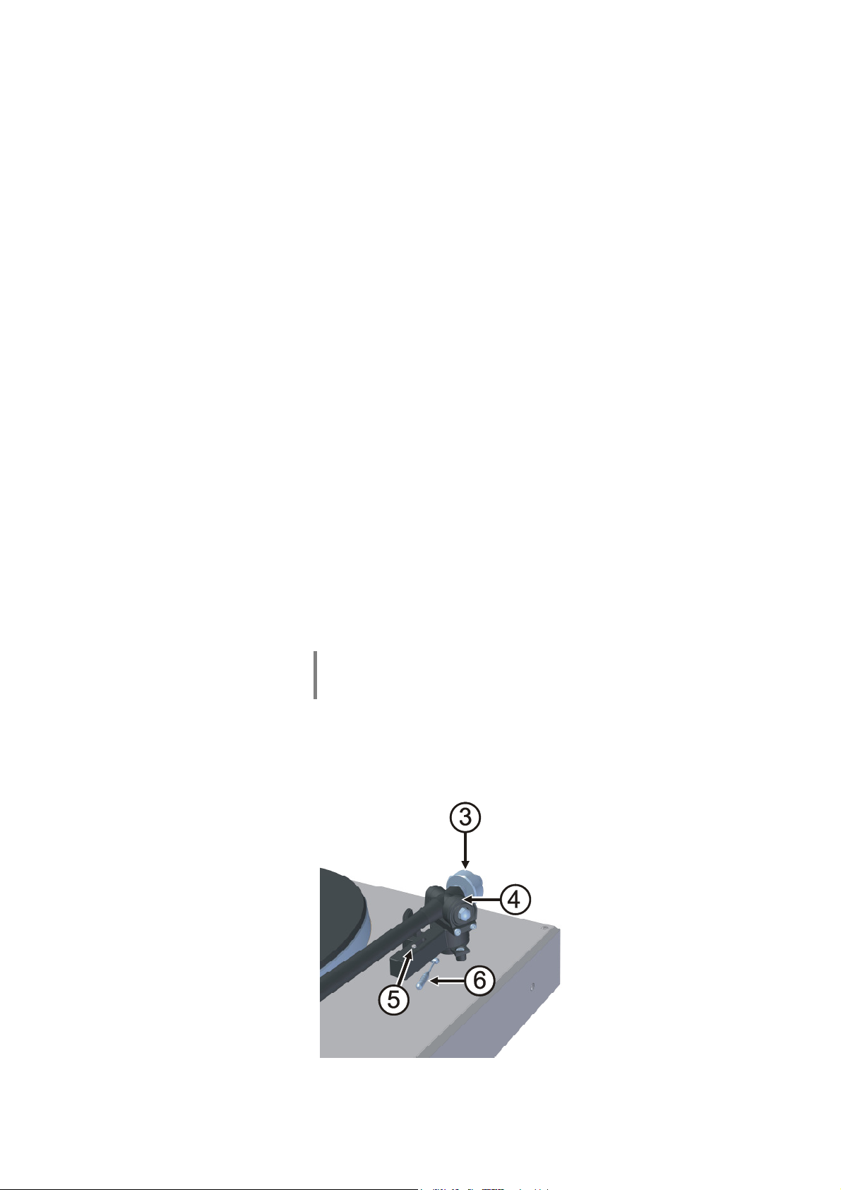
Montage des Gegengewichts und
Kontrolle der Tonarmeinstellungen
Tonarminfos Der TA 301 A Tonarm ist ein Präzisionsinstrument, welches mit höchster
Genauigkeit gefertigt und justiert wurde. Um seine hervorragenden
Abtasteigenschaften zu erhalten sollten alle Teile des Tonarms äußerst
vorsichtig behandelt werden. Bei Einhaltung der folgenden Hinweise wird sich
der Tonarm als ein zuverlässiges Produkt erweisen, das Ihnen für viele Jahre
Musikgenuß auf höchstem Niveau, kombiniert mit einfacher Handhabung
garantiert.
Einstellung der Auflagekraft
Bei G1260R Modellen, die ohne das optional erhältliche Tonabnehmersystem
geliefert werden installieren Sie bitte zuerst Ihr System und justieren Sie es wie
im Kapitel „Einbau und Ausrichtung eines Tonabnehmersystems“ beschrieben.
Bei G1260R Modellen, die ab Werk mit montiertem Tonabnehmersystem
geliefert werden ist das System bereits korrekt justiert und optimal eingestellt.
Bei Auslieferung ist das Tonarmgegengewicht vom Tonarm abgenommen,
um das empfindliche Tonarmlager zu schonen. Das Gegengewicht befindet
sich im Zubehör und muss vor Inbetriebnahme installiert und eingestellt
werden. Stecken Sie dazu das Tonarmgewicht auf das hintere Ende des
Tonarms auf. Stellen Sie das seitlich am Lager des Arms befindliche Einstellrad
für das Auflagegewicht auf „0“.
Wenn der Arm am vorderen Ende nun nach unten hängt, schieben Sie das
Tonarmgewicht weiter nach hinten, steigt das vordere Ende des Arms auf,
bewegen Sie das Tonarmgewicht weiter nach vorn. Bringen Sie auf diese
Weise das Gewicht in die Position, in der der Arm knapp über der
Plattentellerebene „schwebt“ und sich selbstätig weder aufwärts- noch abwärts
bewegt.
Nun kann die vom Hersteller Ihres Tonabnehmersystems empfohlene
Auflagekraft durch Drehen des Einstellrades für das Auflagegewicht
eingestellt werden.
Hinweis:
In der Regel empfiehlt sich eine Einstellung der Auflagekraft an der oberen
Grenze des vom Hersteller des Systems genannten Bereiches.
Einstellung der
Antiskatingkraft
Die Antiskatingkraft wird mit dem Schieberegler an der Tonarmbasis
eingestellt. Die Markierungen der Skala an diesem Regler korrespondieren mit
der Auflagekraft des Tonabnehmersystems in Gramm.
Wenn Sie z.B. eine Auflagekraft von 1,5g eingestellt haben, stellen Sie den
Schieberegler bitte ebenfalls auf einen Wert von 1,5 ein.
Einstellelemente des Tonarms
13
Page 14
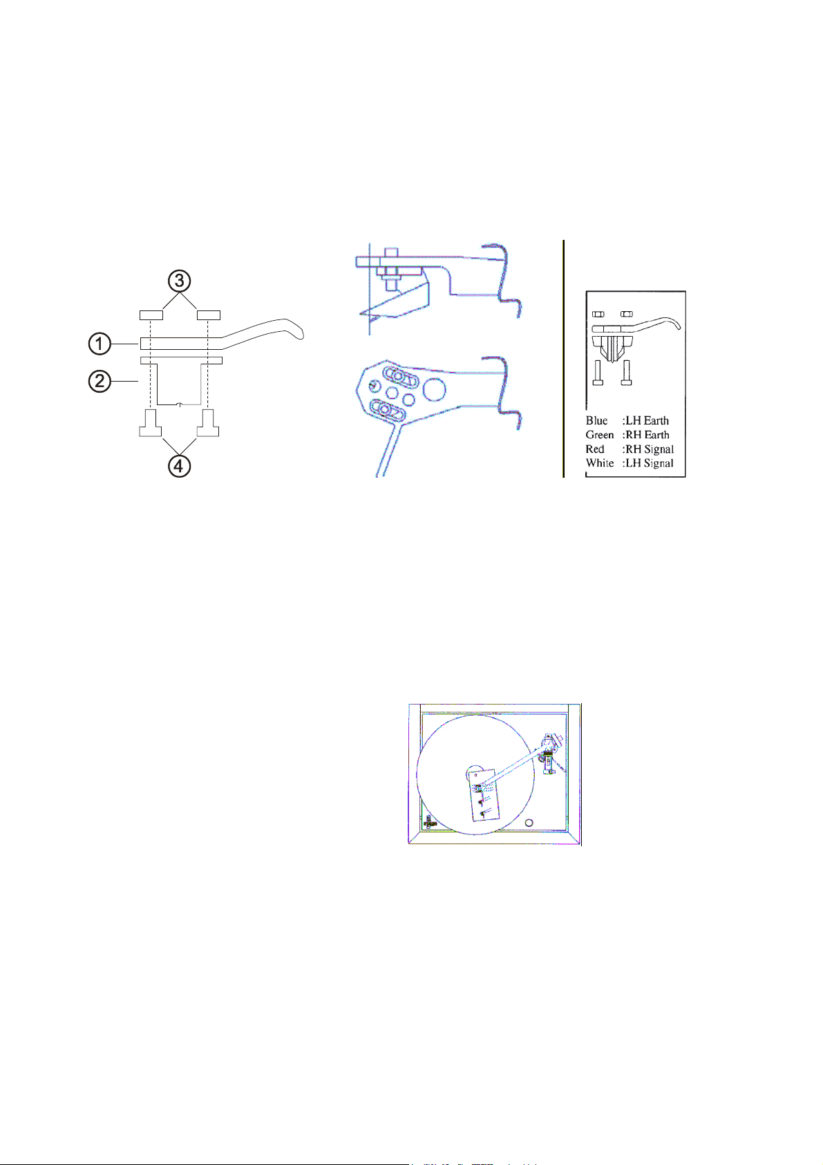
Einbau und Ausrichtung eines
Tonabnehmersystems
Einbau
Tonabnehmersystem
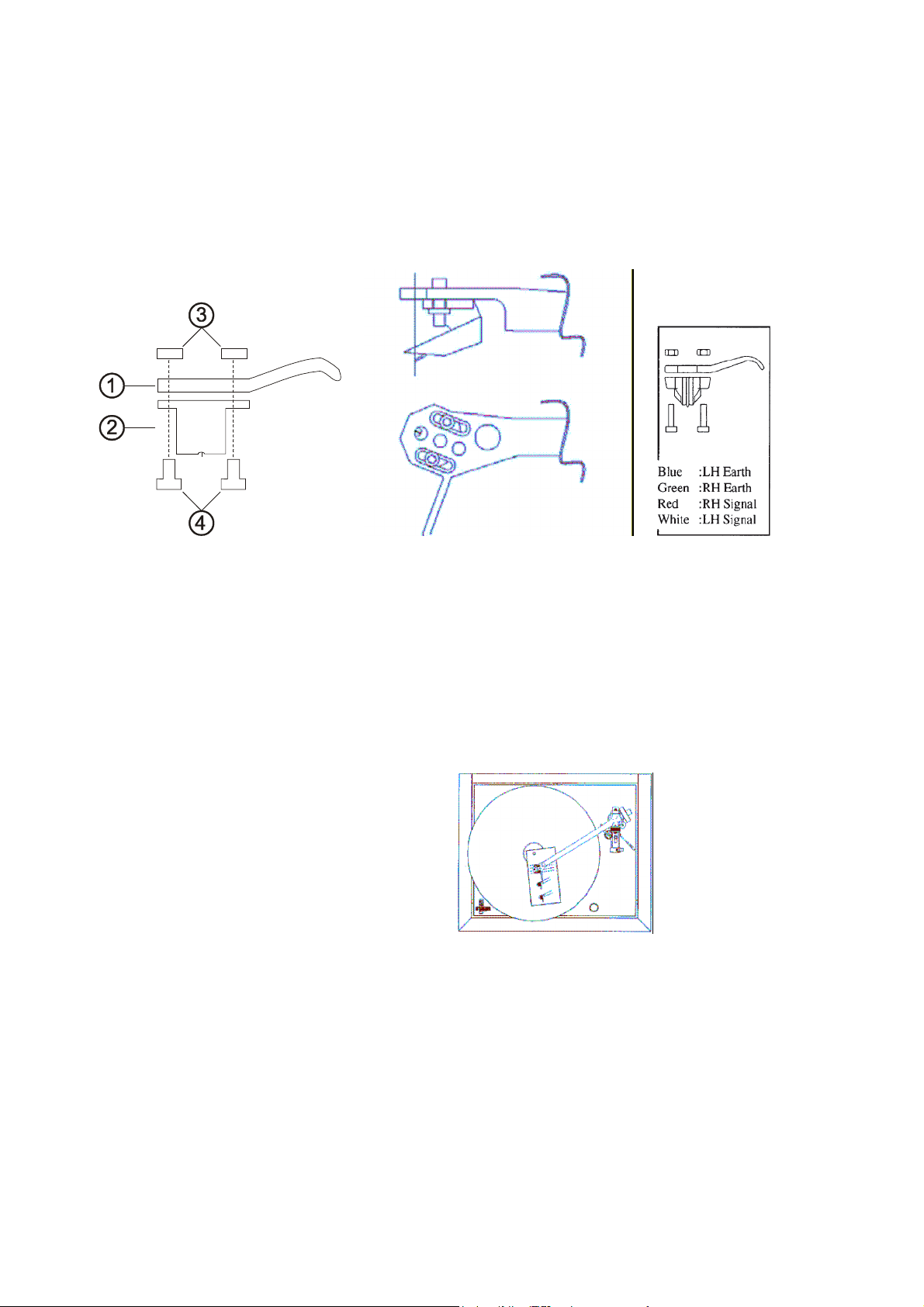
Befestigen Sie das Tonabnehmersystem (2) mit geeigneten Schrauben (4) und
Muttern (3) in den Langlöchern am vorderen Ende des Tonarms (1). Stecken
Sie die aus dem Arm ragenden Kabel an den Anschlußstiften des
Tonabnehmersystems gemäß folgender Tabelle auf.
Blau Masse – linker Kanal
Weiß Signal – linker Kanal
Grün Masse – rechter Kanal
Rot Signal – rechter Kanal
Ausrichtung
Tonabnehmersystem
Legen Sie die im Zubehör des G1260R befindliche Schablone so auf den
Plattenteller auf, dass die Plattentellerachse durch das Loch in der Schablone
greift. Lösen Sie die Schrauben des Tonabnehmersystems ein wenig, sodaß
Sie das System in den Langlöchern des Arms bewegen können. Schwenken
Sie den Tonarm über das Linienmuster auf der Schablone und richten Sie das
Tonabnehmersystem wie auf der Schablone dargestellt aus. Ziehen Sie dann
die Halteschrauben des Systems fest an.
14
Page 15

Sicherheitshinweise
Alle in diesem Gerät verwendeten Bauteile entsprechen den geltenden
deutschen und europäischen Sicherheitsnormen und -standards.
Eine genaue Qualitätsprüfung aller Materialien, die sorgfältige Produktion,
sowie die vollautomatische, rechnergesteuerte Endkontrolle eines jeden
Gerätes gewährleisten die hohe Produktqualität und die Einhaltung aller
Spezifikationen.
Zu Ihrer eigenen Sicherheit sollten Sie bitte unbedingt diese Betriebsanleitung
vollständig lesen und insbesondere die Aufstellungs-, Betriebs- und
Sicherheitshinweise genau befolgen.
Aufstellung
Stromversorgung
Netzkabel / Netzstecker
Geräteöffnungen
Aufsichtspflicht
Reparatur und
Beschädigung
Das Gerät ist so aufzustellen, dass eine Berührung sämtlicher
Geräteanschlüsse (insbesondere durch Kinder) ausgeschlossen ist. Die
Hinweise und Angaben im Kapitel 'Aufstellung und Verkabelung' sind unbedingt zu beachten.
Die für das Gerät erforderliche Stromversorgung ist dem Aufdruck an der
Netzgerätebuchse zu entnehmen. An andere Stromversorgungen darf das
Gerät nicht angeschlossen werden. Bei längerer Nichtbenutzung sollte der
Netzstecker des Gerätes aus der Steckdose gezogen werden.
Netzkabel müssen so verlegt werden, dass keine Gefahr der Beschädigung (z.
B. durch Trittbelastung oder durch Möbelstücke) besteht. Besondere Vorsicht
ist dabei an den Steckern, Verteilern und an den Anschlussstellen des Gerätes
geboten.
Abziehen des Netzsteckers trennt das Gerät bei Wartung oder Servicearbeiten
vom Netz. Bitte achten Sie darauf, dass der Stecker ohne Schwierigkeiten zugänglich und benutzbar ist.
Durch die Lüftungsschlitze dürfen keine Flüssigkeiten oder Fremdkörper in das
Gerät gelangen. Im Inneren führt das Gerät Netzspannung, es besteht die
Gefahr eines tödlichen elektrischen Schlages. Auf den Netzstecker darf keine
übermäßige Krafteinwirkung ausgeübt werden.
Schützen Sie das Gerät vor Tropf- und Spritzwasser und stellen Sie keine
Blumenvasen oder andere Gefäße mit Flüssigkeiten auf das Gerät.
Wie alle Elektrogeräte so sollte auch dieses Gerät nicht unbeaufsichtigt
betrieben werden. Es ist darauf zu achten, dass es für kleine Kinder
unerreichbar ist.
Das Gerät darf nur vom qualifizierten Fachmann geöffnet werden. Reparaturen
und das Auswechseln von Sicherungen sind von einer autorisierten
Fachwerkstatt durchzuführen. Außer den in der Betriebsanleitung beschriebenen Handgriffen dürfen vom Benutzer keinerlei Arbeiten am Gerät
vorgenommen werden.
Bei Beschädigungen oder bei Verdacht auf eine nicht ordnungsgemäße
Funktion des Gerätes sollte sofort der Netzstecker gezogen und das Gerät zur
Überprüfung in eine autorisierte Fachwerkstatt gegeben werden.
Überspannung
Überspannungen im Stromversorgungsnetz, dem Kabelnetz oder auf
Antennenanlagen, wie sie z. B. bei Gewittern (Blitzschlag) oder statischen
Entladungen auftreten können, stellen eine Gefährdung für das Gerät dar.
Spezielle Vorschaltgeräte, wie Überspannungsprotektoren oder die
'Power Bar' Netzanschlussleiste, bieten einen gewissen Schutz vor
Gerätebeschädigungen aus o.g. Gründen.
Eine absolute Sicherheit vor Beschädigung durch Überspannungen kann aber
nur eine vollständige Trennung des Gerätes vom Netz und den
Antennenanlagen gewährleisten.
Ziehen Sie zur Trennung sämtliche Netz- und Antennenstecker Ihrer HiFi
Anlage bei Überspannungsgefahr (z. B. bei heraufziehenden Gewittern) aus
den Steckdosen.
Sämtliche Netzversorgungs- und Antennenanlagen, an die das Gerät
angeschlossen wird, müssen den geltenden Bestimmungen entsprechen und
fachgerecht von einem zugelassenen Installationsbetrieb ausgeführt sein.
Viele Versicherungsgesellschaften bieten im Rahmen der Hausratversicherung
eine Blitzschutzversicherung für Elektrogeräte an.
15
Page 16

Bestimmungsgemäßer
Gebrauch
Das Gerät ist ausschließlich zur Ton- und/oder Bildwiedergabe im Heimbereich
in trockenen Räumen unter Berücksichtigung aller in dieser Anleitung
gemachten Angaben bestimmt.
Bei allen anderen Einsatzzwecken, insbesondere in medizinischen oder
sicherheitsrelevanten Bereichen, ist vorher die Zulassung und Eignung des
Gerätes für diesen Einsatz mit dem Hersteller abzuklären und schriftlich
genehmigen zu lassen.
Geräte mit Rundfunk- oder Fernsehempfangsteilen dürfen im Rahmen der
gültigen 'Allgemeingenehmigung für Ton- und Fernseh-
Rundfunkempfänger', veröffentlicht im Amtsblatt des Bundesministers für
Post und Telekommunikation, in der Bundesrepublik Deutschland betrieben
werden.
Mit dem Gerät dürfen nur Aussendungen empfangen oder wiedergegeben
werden, die für die Allgemeinheit bestimmt sind. Der Empfang oder die
Wiedergabe anderer Aussendungen (z. B. des Polizei- oder Mobilfunks) ist
nicht gestattet.
Gerätezulassung und
Konformität mit EGRichtlinien
Das Gerät entspricht im Originalzustand allen derzeit gültigen deutschen und
europäischen Vorschriften. Es ist zum bestimmungsgemäßen Gebrauch in der
EG zugelassen.
Durch das am Gerät befindliche Zeichen erklärt die Konformität mit
den EG-Richtlinien 2006/95/EG und 2004/108/EG und den daraus abgeleiteten
nationalen Gesetzen.
Die unveränderte, unverfälschte Werksseriennummer muss außen am Gerät
vorhanden und gut lesbar sein! Die Seriennummer ist Bestandteil unserer
Konformitätserklärung und damit der Betriebszulassung des Gerätes!
Seriennummern am Gerät und in den originalen Begleitpapieren
(insbesondere den Kontroll- und Garantiezertifikaten) dürfen nicht entfernt oder
verändert werden und müssen übereinstimmen.
Bei Verstoß gegen diese Bestimmungen gilt die Konformitätszusage von als
widerrufen und ein Betrieb des Gerätes innerhalb der EG ist untersagt und
aufgrund geltender EG und nationaler Gesetze unter Strafandrohung verboten.
Durch Umbauten am Gerät oder durch Reparaturen oder sonstige Eingriffe von
nicht von autorisierten Werkstätten oder sonstigen Dritten verliert das
Gerät seine Zulassung und Betriebserlaubnis.
An das Gerät dürfen nur original Zubehörteile oder solche Zusatzgeräte
angeschlossen werden, die ihrerseits zugelassen sind und allen geltenden
gesetzlichen Vorschriften genügen.
Auch mit Zusatzgeräten oder als Teil einer Anlage darf das Gerät nur zu den im
Abschnitt 'Bestimmungsgemäßer Gebrauch' genannten Anwendungen
eingesetzt werden.
Entsorgung des Gerätes
Für die spätere Entsorgung dieses Produkts stehen örtliche Sammelstellen für
Elektroschrott zur Verfügung.
16
Page 17
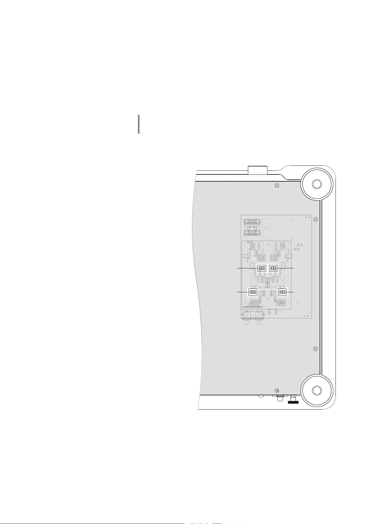
Der G 1260 R PHONO Vorverstärker (optional)
1234123
4
1234123
4
VORN
FRONT
BODENBLECH
BOTTOM COVER
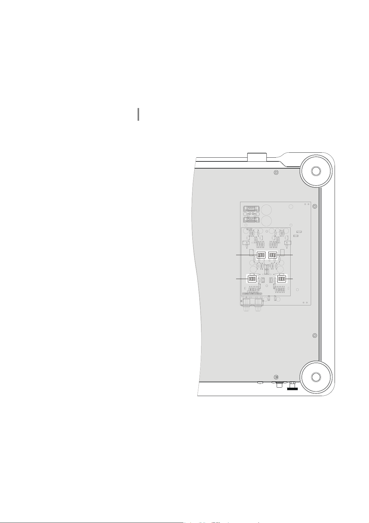
Der G 1260 R kann mit einem optionalen Phono-Vorverstärker ausgerüstet
werden. Sofern werksseitig Phonovorverstärker und Tonabnehmersystem
installiert sind, sind diese bereits werksseitig optimal eingestellt. Die in diesem
Kapitel beschriebenen Einstellungen brauchen in diesem Falle nicht
durchgeführt werden.
Im Falle, dass ein fremdes Tonabnehmersystem montiert wird, kann der
Vorverstärker über Codierschalter, die über Öffnungen im Bodenblech zugänglich sind an das jeweilige System angepasst werden. Die Lage der
Codierschalter geht aus der nachfolgenden Abbildung hervor.
Der Phonovorverstärker ist in einer Variante für MM oder für MC Tonabnehmer
erhältlich. Für beide Versionen sind die jeweiligen Einstellwerte weiter unten in
getrennten Tabellen angegeben.
Empfindlichkeit
Sensitivity
Eingangsimpedanz /
Eingangskapazität
Input Impedance /
Capacitance
S2 S52
S51S1
HINTEN
REAR
Abb.1: G 1260 R Ansicht von unten
17
Page 18

Einstellungen der Codierschalter
Die einstellbaren Werte für Eingangsimpedanz und Eingangsempfindlichkeit können aus den
folgenden Tabellen entnommen werden.
Vorverstärker PH-G10 MM
Schalterstellung
1 2 3 4
OFF OFF OFF OFF ... 120 pF 6 mV ... 10.0 mV
OFF OFF OFF
OFF OFF
OFF OFF
OFF
OFF
OFF
OFF
ON
ON
ON
ON
ON ON
ON ON
ON ON ON
ON ON ON ON
ON
ON
ON ON
ON ON ON
OFF OFF OFF 291 pF ... 340 pF
OFF OFF
OFF
OFF
ON
ON ON
OFF OFF 191 pF ... 220 pF
OFF
ON
ON ON
OFF OFF 401 pF ... 440 pF
OFF
ON
OFF 141 pF ... 160 pF 2,5 mV ... 3,5 mV
ON 221 pF ... 240 pF
OFF 241 pF ... 260 pF
ON
OFF 361 pF ... 380 pF
ON
OFF 461 pF ... 480 pF
Eingangskapazität
(Schalter S51, S1)
121 pF ... 140 pF
161 pF ... 190 pF
261 pF ... 290 pF
341 pF ... 360 pF
381 pF ... 400 pF
441 pF ... 460 pF
481 pF ... 500 pF
Empfindlichkeit
(Schalter S52, S2)
3,5 mV ... 6,0 mV
1.5 mV ... 2.5 mV
1 ... 1.5 mV
= empfohlene Einstellungen für Ortofon 2M Bronze
Vorverstärker PH-G10 MC
Schalterstellung
1 2 3 4
OFF OFF OFF OFF 450 Ω ... 650 Ω > 2000 µV
OFF OFF OFF
OFF OFF
OFF OFF
OFF
OFF
OFF
OFF
ON
ON
ON
ON
ON ON
ON ON
ON ON ON
ON ON ON ON
ON
ON
ON ON
ON ON ON
OFF OFF OFF 20 Ω ... 29 Ω
OFF OFF
OFF
OFF
ON
ON ON
OFF OFF 50 Ω ... 84 Ω 400 µV ... 600 µV
OFF
ON
ON ON
OFF OFF 16 Ω ... 19 Ω
OFF
ON
OFF 130 Ω ... 199 Ω 800 µV ... 1200 µV
ON
OFF 30 Ω ... 49 Ω
ON
OFF
ON
OFF
Eingangsimpedanz
(Schalter S51, S1)
200 Ω ... 449 Ω
85 Ω ... 129 Ω 600 µV ... 800 µV
... 15 Ω
Empfindlichkeit
(Schalter S52, S2)
1200 µV ... 2000 µV
300 µV ... 400 µV
200 µV ... 300 µV
160 µV ... 200 µV
100 µV ... 160 µV
18
Page 19

Betriebsstörungen
Viele Betriebsstörungen haben eine einfache Ursache, die sich leicht beheben lässt. Im folgenden Abschnitt sind einige
mögliche Störungen sowie Maßnahmen zu deren Behebung aufgeführt. Sollte sich eine aufgetretene Störung durch
diese Hinweise nicht beheben lassen, so ziehen Sie bitte umgehend den Netzstecker und wenden sich an eine Fachwerkstatt.
Gerät schaltet nicht ein
(Leuchtdiode bleibt dunkel).
Wiedergabe hat
Tonschwankungen.
Ursache:
Netzkabel nicht richtig angeschlossen.
Abhilfe:
Überprüfen und fest einstecken.
Ursache 1:
Lager nicht ausreichend geölt.
Hilfe:
Lager ölen, siehe Kapitel 'Montage des Plattentellers'.
Ursache 2:
Treibriemen verbraucht oder verschlissen.
Hilfe:
Treibriemen ersetzen.
Ursache 3:
Treibriemen verölt.
Hilfe:
Treibriemen und Antriebsräder bzw. Plattenteller mit Spiritus getränktem
Lappen reinigen.
Achtung:
Dabei darf kein Spiritus auf die Acrylteile gelangen, da diese sonst reißen
können.
Siehe auch Kapitel 'Pflege des Gerätes'.
Brummenstörungen
Ursache:
G 1260 R oder angeschlossenes Gerät hat keinen Erdanschluss.
Abhilfe:
Stellen Sie eine zusätzliche Chassis-Verbindung mittels Massekabel her
(G 1260 R GND-Erdungsklemme zur Erdungsklemme des angeschlossenen
Gerätes).
19
Page 20

20
Page 21

English
21
Page 22

Welcome!
We are delighted that you have purchased a product. The G 1260 R turntable is a Hi-Fi unit of the highest quality
which has been carefully developed to satisfy all the wishes of the demanding music lover.
The innovative technology, the solid, carefully considered design and the high-quality materials employed all help to
ensure that this turntable will fulfil your most exacting demands over a period of many years.
Careful quality testing of all materials, painstaking assembly by highly qualified staff and a fully automatic computercontrolled final quality control procedure ensure high product quality and a unit which meets the specification in every
respect.
In our equipment production processes we avoid the use of materials which are environmentally harmful such as
chlorine-based solvents and CFCs.
As far as possible we avoid the use of plastics - especially PVC - in our equipment; instead we use metals or other nonharmful materials which are easily recycled and which also provide effective electrical shielding.
The heavy all-metal case of the G 1260 R eliminates the danger of adverse effects on reproduction quality caused by
external sources of interference. This ensures that the electro-magnetic radiation (electro-smog) generated by the unit is
well shielded, and thereby reduced to an absolute minimum.
Our range of accessories includes high-quality cables and connectors, as well as sound system furniture designed to
match the style and appearance of our equipment.
Please accept our thanks for placing your faith in us. We hope that you will enjoy many hours of pleasure with your
turntable.
elektroakustik GmbH & Co KG
All components used in this device satisfy the current German and European safety norms and standards. For
This product fulfils the requirements of the low-voltage directives (72/23/EEC), the EMV directives (89/336/EEC,
92/31/EEC) and the CE marker directives (96/68/EEC).
your own safety please be sure to read right through these operating instructions. It is especially important to
observe the information regarding setting up and operating the equipment, and the safety notes.
22
Page 23

Contents
Operating the unit
Front panel controls ....................................................................................................... 24
Playing a disc ................................................................................................................. 24
Connections, using the unit for the first time
Back panel connections ................................................................................................. 26
Setting up, wiring ........................................................................................................... 27
Fitting the base platter ................................................................................................... 29
Fitting the counterweight, checking the tone arm settings ............................................ 31
Installing and aligning a pick-up cartridge ..................................................................... 32
Safety notes ................................................................................................................... 33
FCC Information to the user .......................................................................................... 34
The G 1260 R PHONO pre-amplifier (optional) ............................................................. 35
Code switch settings ...................................................................................................... 36
Trouble shooting ............................................................................................................ 37
Appendix
Specification .................................................................................................................. 39
23
Page 24
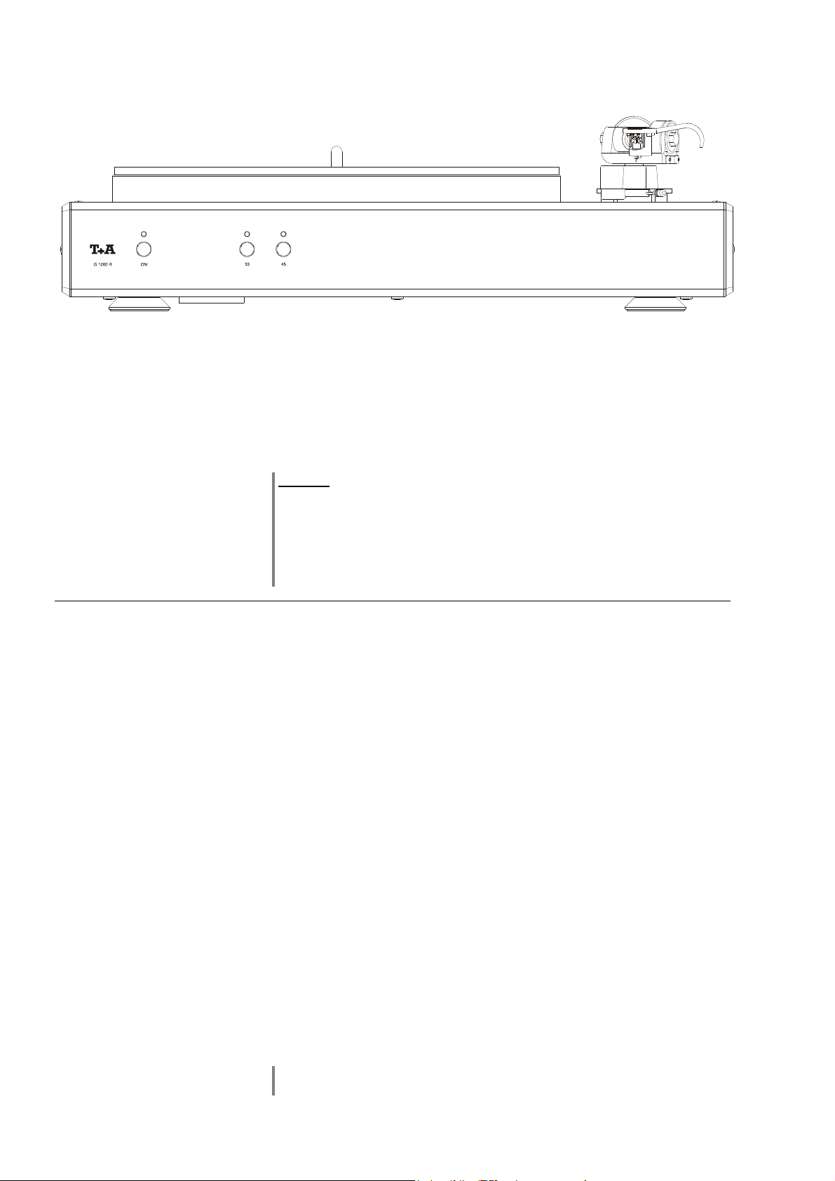
Front panel controls
33 / 45
(On / Off switch)
A brief press on the button switches the unit on and off. When the machine is
switched on, the indicator light above the button glows.
If the turntable is used in conjunction with an R-system, the G 1260 R is
switched on via the existing R
inputs (“AUX1” or “AUX2”) as listening source. When you switch the R-system
off, the G 1260 R is automatically switched off.
Caution!
The mains button is not a mains isolation switch. Even when the LED is
not glowing parts of the machine remain connected to the mains power
supply (Standby mode). The stand-by current drain is stated in the chapter
entitled 'Specification'.
If the unit is not to be used for a long period we recommend that you
disconnect the mains plug at the wall socket.
Link
connection when you select one of the phono
Disc speed select button
When the disc platter is stationary, pressing one of the buttons starts the platter
motor running at the rotational speed stated above the button. The LED above
the button flashes while the motor runs up to speed. The LED glows constantly
as soon as the nominal speed is reached.
Simply press the other of the two buttons to change the disc speed.
Stopping the platter motor
When the disc platter is turning, it can be stopped by briefly pressing the button
below the glowing LED: the platter is actively braked, and comes to rest after a
brief period.
Playing a disc
Operation
• A brief press on the
• Place the disc on the platter.
• We recommend that you always remove superficial dust from the disc
before you play it, e.g. using a carbon fibre brush or an anti-static cloth.
• Press the 33 or 45 rpm button (as required by the disc on the platter) in
order to start the motor.
• Move the tone arm inward until it is above the desired groove. the LED
above the selected disc speed button glows constantly when the nominal
speed is reached, indicating that you can slowly lower the tone arm onto
the disc by operating the tone arm lift lever (see illus. 'Adjusting
elements on the ton arm', chapter 'Fitting the counterweight, checking
the tone arm').
If you are using the optional cover, you must remove it before operating the
G 1260 R.
button switches the machine on.
24
Page 25

Installation
Using the unit for the first time
Safety notes
This section describes all those aspects which are of fundamental importance when setting up and using the turntable
initially. This information is not required when the unit is in normal daily use, but should nevertheless be read carefully
and observed before the machine is used for the first time.
25
Page 26
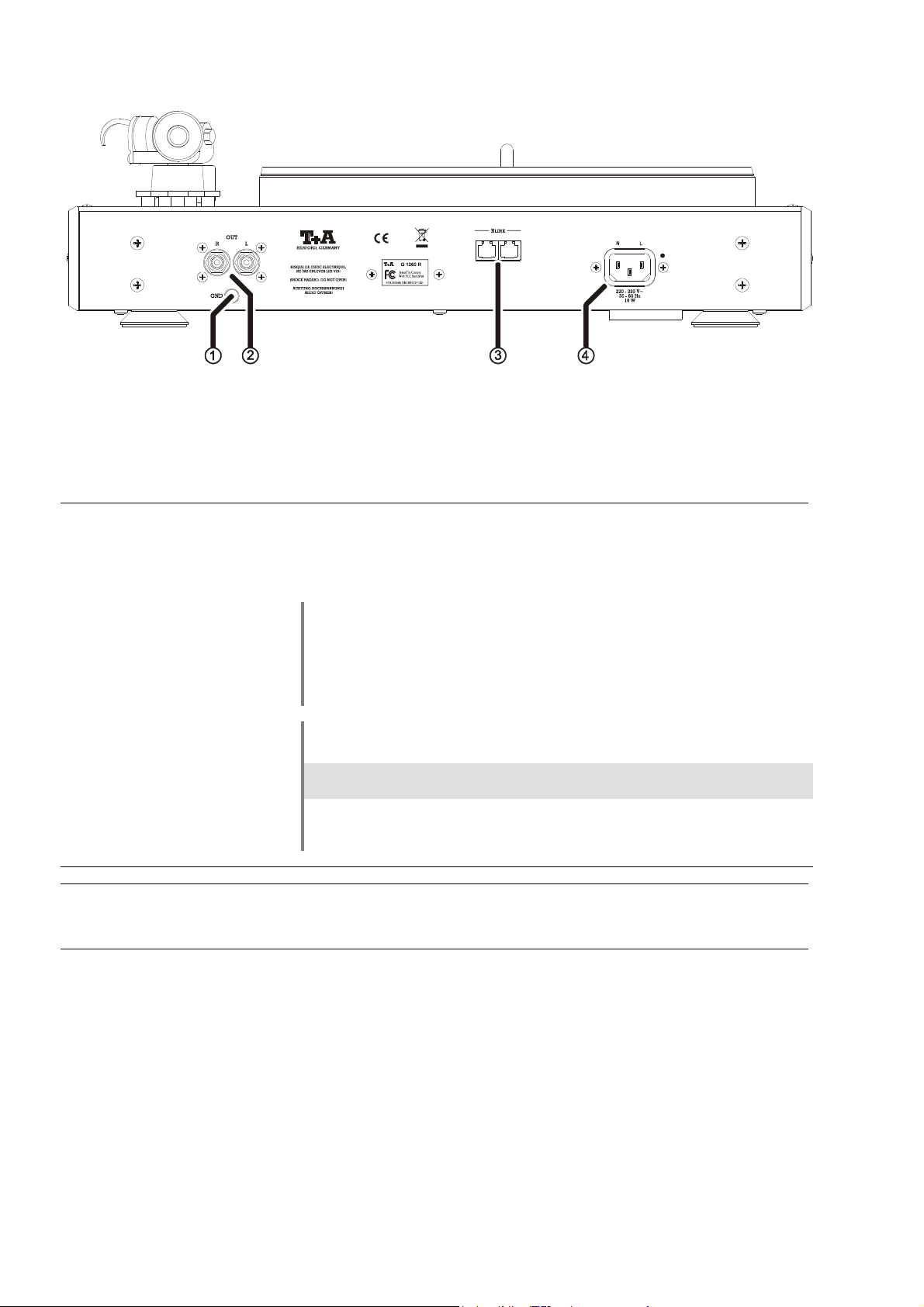
Connections
GND
OUT
Earth (ground) clamp
Only for G 1260 R version without internal phono module.
Connect this terminal to the earthing point on your amplifier.
Do not use if internal phono module is installed.
Output sockets
If your G 1260 R version is not supplied with a factory-fitted PHONO pre-
amplifier module:
Connect these sockets to a PHONO input on your amplifier.
Please note: if the G 1260 R is not fitted with a phono module, this facility must
be present in your amplifier or receiver.
If your G 1260 R is supplied with a factory-fitted PHONO pre-amplifier
module:
Connect these sockets to a high-level (line) input on your amplifier.
Use one of the following inputs to connect the G 1260 R, depending on your
model of amplifier:
Input Device
AUX 2
AUX1
P1230/1260R, PA1230/1260R, PA1530R, R1530 R
R1230R
R
LINK
Netzeingang
Control input for connecting to units with the R
PA 1260 R amplifier).
The mains lead should be connected to this socket.
26
LINK
control system (e. g.
Page 27

Setting up, wiring
Carefully unpack the G 1260 R and store the original packing materials
carefully. The carton and packing are specially designed for this unit and will be
needed again if you wish to move the equipment at any time.
Please be sure to read the safety notes in these instructions.
If the unit gets very cold (e. g. when being transported), condensation may form
inside it. Please do not switch it on until it has had plenty of time to warm up to
room temperature, so that any condensation evaporates completely.
Before placing the unit on a delicate surface, please check the compatibility of
the lacquer and the unit’s feet at a non-visible point.
The turntable should be placed on a rigid, level base which is not subject to
vibration. The feet are fitted with metal de-coupling elements, and are therefore
not rigid. If you are setting up the unit on resonance absorbers or de-coupling
components make sure that they do not compromise its stability.
The unit should be set up in a dry, well-ventilated location, out of direct sunlight
and away from radiators.
It must not be located close to heat-producing objects or devices, or anything
which is heat-sensitive or highly inflammable.
When installing the unit on a shelf or in a cupboard it is essential to provide an
adequate flow of cooling air, to ensure that the heat produced by the unit is
dissipated effectively. Any heat build-up will shorten the life of the unit and
could be a source of danger.
Deploy all mains cables, loudspeaker cables and the remote control cable as
far as possible from low-level cables (inter-connects) and aerial cables. Never
route them over or under the receiver.
Notes on wiring the system:
• Be sure to push all plugs firmly into their sockets. Loose connections can
cause hum and other unwanted noises.
• To achieve the maximum signal : noise ratio the mains plug should be
connected to the wall socket in such a way that phase is connected to the
mains input socket contact which is marked with a dot (). If you do not know
the phase of your mains socket, a special device can be used to determine it;
your local dealer will be able to help you here.
• We recommend the use of 'POWER LINE' ready-made mains cables in
conjunction with a 'POWER BAR' mains distribution panel, which features an
integral phase indicator.
• When the wiring of the system is complete, please set the volume control to a
very low level before switching the system on.
If you encounter problems when setting up and using the turntable for the first
time, please remember that the cause is often simple, and may be equally
simple to eliminate. Please refer to the section of these instructions entitled
'Trouble-shooting'.
27
Page 28

Loudspeaker cables and
inter-connects
The loudspeaker cables and inter-connects have a significant influence on the
reproduction quality of the entire system, and their importance should not be
under-estimated. For this reason we strongly recommend the use of highquality cables and connectors.
Our range of accessories includes a series of top-quality cables and
connectors whose characteristics are accurately matched to our loudspeakers
and electronic units, and work superbly with them. For difficult and cramped
arrangements you may also find our non-standard cables useful; the
range includes special lengths and special connectors (e. g. right-angled
versions) with which virtually any problematic location or connection can be
solved.
Mains cables and mains
filters
Mechanical de-coupling
The mains power supply carries the operating energy to your sound system,
but at the same time it also bears interference from remotely located
equipment, radio transmissions and computer systems.
To prevent electro-magnetic interference reaching your equipment we
recommend that you use the special items included in our range of
accessories: the 'POWER FOUR' mains cable with its effective shielding, the
'POWER LINE' ready-made mains leads with ferrite filters, and the 'POWER
BAR' filtered mains distribution panel. In many cases the use of these
accessories provides a further improvement in the reproduction quality of our
equipment.
If you have queries concerning cables and wiring please ask your local
dealer in the first instance, as he will be able to offer competent,
comprehensive and impartial advice. We will also be glad to send you a copy of
our complete information pack on this subject.
The surface and sub-surface on which your high-quality sound system units are
set up have a significant effect on the potential sound quality, and their
importance should not be under-estimated. The base surface should be as
heavy, stable, hard and level as possible.
The turntable is fitted with the newly developed vibration-absorbing case
feet. These feet offer very effective internal damping characteristics and provide a
high level of de-coupling from the base surface. They prevent external sound and
mechanical vibration reaching the pick-up system, where microphony effects can
have an adverse influence on sound quality.
To ensure that the vibration absorbers are able to work properly it is important
that the turntable should be set up without any contact between the case and
the walls or any other surface.
Care of the unit:
Disconnect the mains plug from the wall socket before cleaning the turntable.
To clean the machine simply wipe the surfaces with a soft, damp cloth or
sponge. Do not rub the surfaces with a dry cloth.
Please just use clean water
to moisten the cloth, or water with a small addition of a mild cleaning
agent such as a neutral cleaner, soft soap or similar.
organic solvent which might contain materials such as paint thinners,
alcohol or lighter fuel.
Before using the unit again be sure to check that there are no short-circuits at
the connections, and that all connectors are correctly fitted and firmly inserted.
Never use any
28
Page 29
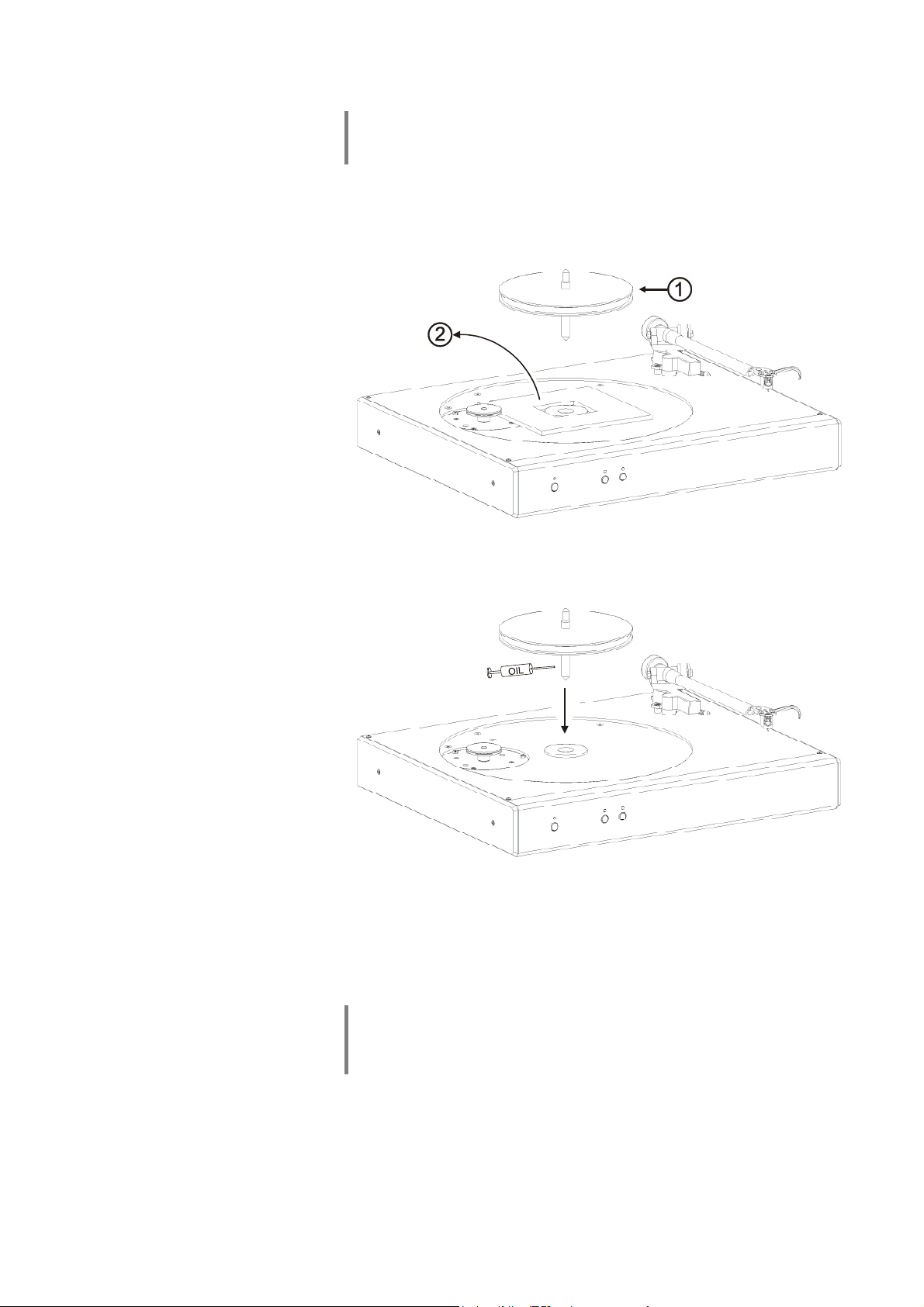
Fitting the base platter
Important note concerning subsequent stages of assembly:
Please take great care to avoid oil getting onto the drive belt or the belt pulley.
Take care to avoid any dirt soiling the platter bearing.
1. Withdraw the belt pulley () from the platter bearing, complete with the
plat-ter spindle.
2. Remove the transport immobiliser ().
3. Thoroughly oil the platter spindle and the bearing indentation using the oil
syringe supplied.
4. Replace the platter spindle in the bush, turning it and lightly pressing it
down at the same time. Please take care to keep the spindle exactly
vertical; the spindle should slide smoothly into the bush.
5. The belt pulley must be pushed down as far as possible; the belt pulley will
slowly descend on the spindle. Wait until the point of the bearing makes
contact with the bottom of the bush.
Note:
It may take some while for all the air to escape from the bearing, and the
spindle to take its proper place in the bush, since the clearance in the bearing
is extremely slight. Please allow some time for this (up to thirty minutes).
29
Page 30
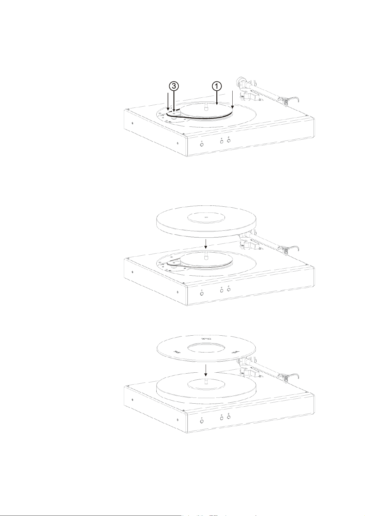
6. Once the belt pulley has reached its final position, rotate the pulley by hand
to ensure that it revolves smoothly.
7. Place the drive belt round the platter drive wheel () and the belt pulley
(), as shown in the drawing.
8. Hold the disc platter exactly level, and carefully lower it vertically onto the
spindle.
9. Now lay the rubber mat on the disc platter.
30
Page 31
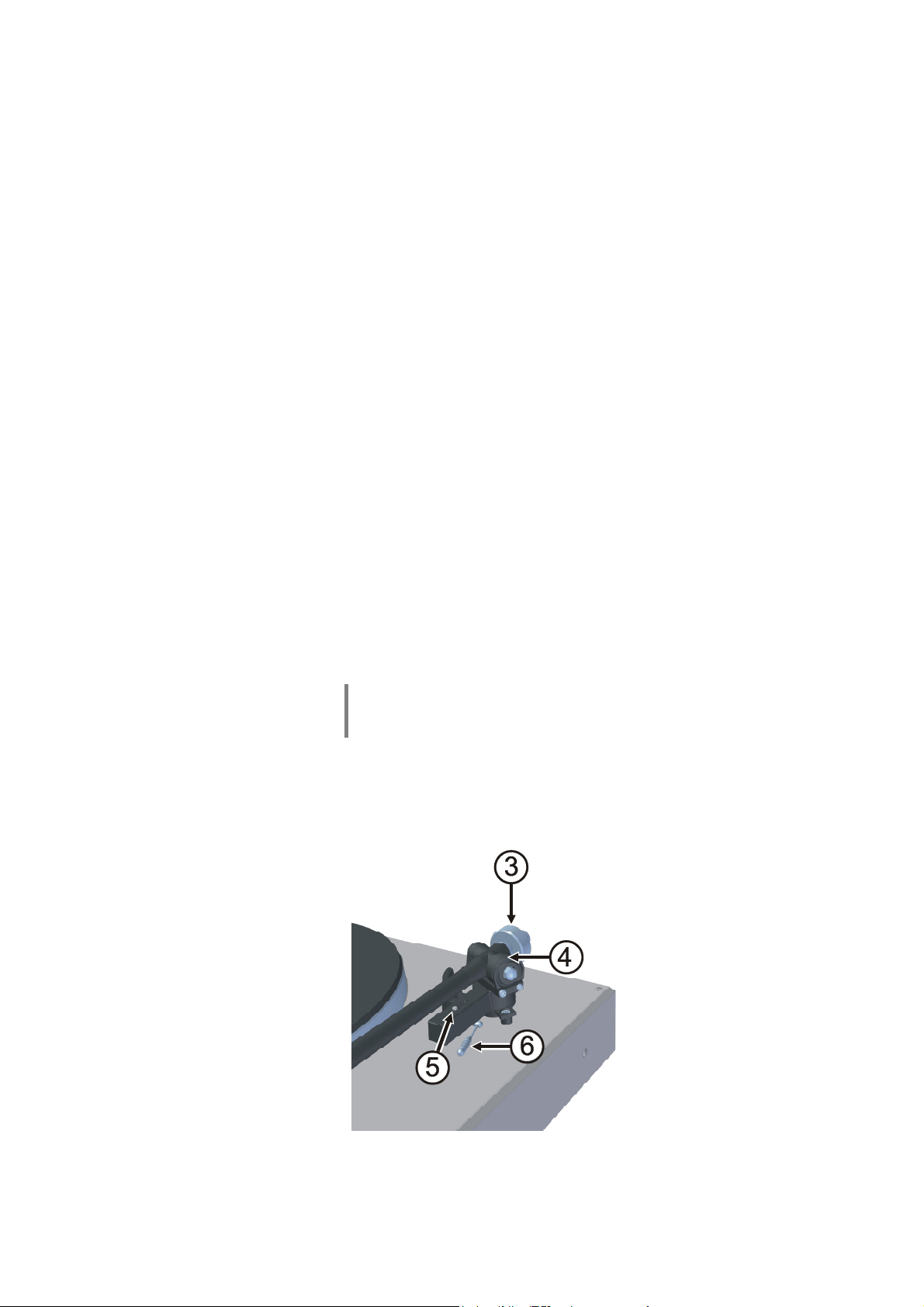
Fitting the counterweight,
checking the tone arm settings
Tone arm information The TA 301 A tone arm is a precision instrument which has been
manufac-tured and adjusted to the highest standards of precision. Please
handle all of the tone arm’s parts with extreme care to ensure that you can
exploit its superb tracking performance to the full. If you observe the following
advice, the tone arm will prove to be a reliable product which will provide you
with musical enjoyment of the highest level for many years, combined with
simple handling.
Setting the tracking force If your G 1260 R is a model which is supplied without the optional pick-up cart-
ridge, please install your pick-up at this point, and set it up as described in the
chapter “Installing and aligning a pick-up cartridge”.
If your G 1260 R is a model which is supplied complete with factory-fitted pickup cartridge, the system is already correctly adjusted and perfectly aligned.
The machine is supplied with the tone arm counterweight separate from the
tone arm; this is necessary in order to avoid damage to the delicate tone arm
bearings. You will find the counterweight in the accessory pack; it must be installed and adjusted before the turntable can be used: plug the counterweight
onto the rear section of the tone arm. Set the adjuster wheel at the side of
the tone arm bearing, and set it to a tracking force of “0”.
If the front end of the arm now hangs down, please move the counterweight
further back; this causes the front end of the tone arm to rise. If the front end of
the arm rises, move the counterweight further forward. In this way you can
adjust the counterweight’s position until the tone arm “hovers” by itself just
above the level of the platter surface, moving neither up nor down.
Setting the anti-skating
force
You can now set the tracking force recommended by the manufacturer of your
pick-up system by rotating the tracking force adjuster wheel .
Note:
In most cases it is advisable to set the tracking force towards the top limit of the
range stated by the pick-up manufacturer.
The anti-skating force is adjusted on the slide control on the base of the
tone arm. The markings on this adjuster’s scale correspond to the tracking
force of the pick-up system in grammes.
For example, if you have set a tracking force of 1.5 g, the slider should also be
set to a value of 1.5.
Adjusting elements on the tone arm
31
Page 32
Installing and aligning
a pick-up cartridge
Installing the pick-up
cartridge
Attach the pick-up cartridge (2) to the front end of the tone arm (1) by threading
suitable screws (4) through the slots and attaching the nuts (3). Locate the
wires projecting from the tone arm, and push them onto the connecting pins on
the pick-up cartridge, as stated in the table below.
Blue Earth – left-hand channel
White Signal – left-hand channel
Green Earth – right-hand channel
Red Signal – right-hand channel
Aligning the
pick-up cartridge
Locate the template in the G 1260 R accessory pack, and lay it on the disc
platter with the platter spindle engaged in the hole in the template. Loosen the
pick-up cartridge retaining screws slightly, so that the cartridge is free to move
in the slots of the tone arm. Move the tone arm over the pattern of lines on the
template, and align the pick-up cartridge with the template. Now carefully
tighten the pick-up cartridge retaining screws.
32
Page 33

Safety notes
All components used in this device satisfy the current German and European
safety norms and standards.
Careful quality testing of all materials, painstaking assembly by highly qualified
staff and a fully automatic computer-controlled final quality control proced.
For your own safety please be sure to read right through these operating
instructions. It is especially important to observe the information regarding
setting up and operating the equipment, and the safety notes.
Installation
Power supply
Mains leads / Mains plug
Enclosure openings
Supervision of device
operation
Service, Damage
The turntable should be set up in such a way that none of the electrical
connections can be touched, especially by children. Be sure to heed the
information included in the section 'Setting up and wiring'.
The power supply required for this machine is printed on the mains supply
socket. The unit must never be connected to a power supply which does not
meet this specification. If the turntable is not to be used for a long period,
disconnect it from the mains supply at the wall socket.
Mains cables must be deployed in such a way that there is no risk of people
tripping over them, or of damage caused by furniture. Particular care is required
with connectors, distribution panels and the turntable’s sockets and other
connections.
Unplugging the mains plug will disconnect the device from the mains for service
and repair. Please make sure that the mains plug is easily accessible.
Liquid or foreign bodies must never be allowed to get inside the case through
the vent slots. Mains voltage is present inside the unit, and there is a risk of
lethal electric shock. Do not exert undue force on the mains connectors.
Protect the turntable from drips and splashes of water. Never place flower
vases or other liquid-filled containers on the unit.
As with all electrical equipment, this device should never be used without
proper supervision. Ensure that it is out of the reach of small children.
The unit should only ever be opened by a qualified specialist technician.
Repairs and fuse replacements should be entrusted to an authorised
specialist workshop. With the exception of the connections and procedures
described in these instructions, no work of any kind may be carried out on the
turntable by unqualified persons.
If the unit is damaged, or if you suspect that it is not functioning correctly,
immediately disconnect the mains plug at the wall socket, and ask an
authorised specialist workshop to check it.
Over voltage
The unit may be damaged by excess voltage in the power supply, the cable
network or in aerial systems, as may occur during thunderstorms (lightning
strikes) or due to static discharges.
Special power supply units and excess voltage protectors such as the
'Power Bar' mains distribution panel offer some degree of protection from
damage to equipment due to the hazards described above.
However, if you require absolute security from damage due to excess voltage,
the only solution is to disconnect the unit from the mains power supply and any
aerial systems.
If you believe there is a danger of voltage spikes (e. g. when an electrical storm
is building up) disconnect all your Hi-Fi system components from the mains and
the aerial sockets.
All mains power supply and aerial systems to which the unit is connected must
satisfy the currently valid regulations, and must be installed by an approved
electrical installer.
Many insurance companies offer lightning damage insurance for electrical
equipment as part of their household insurance service.
33
Page 34

Approved usage
This device is designed exclusively for reproducing sound and/or pictures in the
domestic environment. It must be operated in a dry indoor room which satisfies
all the recommendations stated in these instructions.
Where the equipment is to be used for other purposes, especially in the
medical field or for any application where safety is an issue, it is essential to
establish the unit’s suitability with the manufacturer, and to obtain prior written
approval for such usage.
equipment which includes a radio or television receiving section must be
operated within the regulations laid down by the Post Office and the
Telecommunications authorities in the country in which it is operated.
Such equipment may only be used to receive or reproduce those transmissions
which are intended for public consumption. The reception or reproduction of
other transmissions (e. g. police radio or mobile radio broadcasts) is prohibited.
Device approval and
conformity with EC
directives
Disposing of this
product
In its original condition the unit meets all currently valid European regulations. It
is approved for use as stipulated within the EC.
By attaching the CE symbol to the unit declares its conformity with the EC
directives 2006/95/EG and 2004/108/EG and the national laws based on those
directives.
The original, unaltered factory serial number must be present on the outside of
the unit and must be clearly legible! The serial number is a constituent part of
our conformity declaration and therefore of the approval for operation of the
device.
The serial numbers on the unit and in the original documentation supplied
with it (in particular the inspection and guarantee certificates), must not be
removed or modified, and must correspond.
Infringing any of these conditions invalidates conformity and approval,
and the unit may not be operated within the EC. Improper use of the equipment
makes the user liable to penalty under current EC and national laws.
Any modifications or repairs to the unit, or any other intervention by a workshop
or other third party not authorised by , invalidates the approval and
operational permit for the equipment.
Only genuine accessories may be connected to the unit, or such auxiliary
devices which are themselves approved and fulfil all currently valid legal
requirements.
When used in conjunction with auxiliary devices or as part of a system this unit
may only be used for the purposes stated in the section 'Approved usage'.
The only permissible method of disposing of this product is to take it to your
local collection centre for electrical waste.
FCC Information to the
user
(for use in the United States of America only)
Class B digital device – instructions:
Note: This equipment has been tested and found to comply with the limits for a
Class B digital device, pursuant to Part 15 of the FCC Rules. These limits are
designed to provide reasonable protection against harmful interference in a
residential installation. This equipment generates, uses and can radiate radio
frequency energy and, if not installed and used in accordance with the
instructions, may cause harmful interference to radio communications.
However, there is no guarantee that interference will not occur in a particular
installation. If this equipment does cause harmful interference to radio or
television reception, which can be determined by turning the equipment off and
on, the user is encouraged to try to correct the interference by one or more of
the following measures:
-
Reorient or relocate the receiving antenna.
-
Increase the separation between the equipment and receiver.
-
Connect the equipment into an outlet on a circuit different form that to which
the receiver is connected.
-
Consult the dealer or an experienced radio/TV technician for help.
34
Page 35
The G 1260 R PHONO pre-amplifier (optional)
1234123
4
1234123
4
VORN
FRONT
BODENBLECH
BOTTOM COVER
The G 1260 R can be fitted with an optional phono pre-amplifier. If your
turntable was supplied with the phono pre-amplifier and pick-up cartridge
already fitted, then these parts will already be accurately set up. In this case
you do not need to carry out the adjustments described in this section.
If a different make of pick-up cartridge is fitted, the pre-amplifier can be
adjusted to suit the system by means of coding switches, which are accessible
through openings in the metal base plate. The position of these switches is
shown in the illustration below.
The phono pre-amplifier is available in versions for MM and MC pick-ups. The
set-up values for both versions are shown below in separate tables.
Empfindlichkeit
Sensitivity
Eingangsimpedanz /
Eingangskapazität
Input Impedance /
Capacitance
S2 S52
S51S1
HINTEN
REAR
Abb.1: G 1260 R, underside view
35
Page 36

Code switch settings
The available values for input impedance and input sensitivity are listed in the following tables.
PH-G10 MM pre-amplifier
Switch position
Input capacitance
(switches S51, S1)
Sensitivity
(switches S52, S2)
1 2 3 4
OFF OFF OFF OFF ... 120 pF 6 mV ... 10.0 mV
OFF OFF OFF
OFF OFF
OFF OFF
OFF
OFF
OFF
OFF
ON
ON
ON
ON
ON ON
ON ON
ON ON ON
ON ON ON ON
ON
ON
ON ON
ON ON ON
OFF OFF OFF 291 pF ... 340 pF
OFF OFF
OFF
OFF
ON
ON ON
OFF OFF 191 pF ... 220 pF
OFF
ON
ON ON
OFF OFF 401 pF ... 440 pF
OFF
OFF 141 pF ... 160 pF 2,5 mV ... 3,5 mV
OFF 241 pF ... 260 pF
OFF 361 pF ... 380 pF
OFF 461 pF ... 480 pF
= recommended settings for Ortofon 2M Bronze
ON
ON 221 pF ... 240 pF
ON
ON
121 pF ... 140 pF
161 pF ... 190 pF
261 pF ... 290 pF
341 pF ... 360 pF
381 pF ... 400 pF
441 pF ... 460 pF
481 pF ... 500 pF
3,5 mV ... 6,0 mV
1.5 mV ... 2.5 mV
1 ... 1.5 mV
PH-G10 MC pre-amplifier
Switch position
1 2 3 4
OFF OFF OFF OFF 450 Ω ... 650 Ω > 2000 µV
OFF OFF OFF
OFF OFF
OFF OFF
OFF
OFF
OFF
OFF
ON
ON
ON
ON
ON ON
ON ON
ON ON ON
ON ON ON ON
ON
ON
ON ON
ON ON ON
OFF OFF OFF 20 Ω ... 29 Ω
OFF OFF
OFF
OFF
ON
ON ON
OFF OFF 50 Ω ... 84 Ω 400 µV ... 600 µV
OFF
ON
ON ON
OFF OFF 16 Ω ... 19 Ω
OFF
ON
OFF 130 Ω ... 199 Ω 800 µV ... 1200 µV
ON
OFF 30 Ω ... 49 Ω
ON
OFF
ON
OFF
Input impedance
(switches S51, S1)
200 Ω ... 449 Ω
85 Ω ... 129 Ω 600 µV ... 800 µV
... 15 Ω
Sensitivity
(switches S52, S2)
1200 µV ... 2000 µV
300 µV ... 400 µV
200 µV ... 300 µV
160 µV ... 200 µV
100 µV ... 160 µV
36
Page 37

Trouble shooting
Many problems have a simple cause and a correspondingly simple solution. The following section describes a few
difficulties you may encounter, and the measures you need to take to cure them. If you find it impossible to solve a
problem with the help of these notes please disconnect the unit from the mains and ask your authorised specialist
dealer for advice.
Machine does not switch
on (LED stays dark).
Fluctuating sound.
Cause:
Mains lead not connected correctly.
Remedy:
Check connection, push plug in firmly.
Cause 1:
Bearing not oiled sufficiently.
Remedy:
Oil the bearing: see section entitled ‘Fitting the platter’.
Cause 2:
Drive belt worn or exhausted.
Remedy:
Replace drive belt.
Cause 3:
Drive belt oily.
Remedy:
Clean drive belt, pulleys and / or platter with methylated spirit on a cloth.
Caution:
Keep methylated spirit away from the acrylic parts, as they could crack.
See also the section entitled ‘Care of the machine’.
Unwanted hum
Cause:
The G 1260 R or a device connected to it is not earthed.
Remedy:
Connect a separate chassis earth wire (G 1260 R: earth terminal ‘GND’ to earth
clamp on the machine to which it is connected).
37
Page 38

38
Page 39

Technische Daten / Specification
Prinzip / Principle Riemenangetriebenes High-End Laufwerk im schweren Spezialchassis mit
Körperschallabsorber
High-End belt-driven turntable mounted in special heavy chassis with
structural vibration absorber
Antrieb / Drive system Quarzgeregelter Synchronmotor mit DSP-gesteuerter, exakter Optimierung
der Kurvenform der Motorspulenspannung.
Quartz-controlled synchronous motor with precision DSP-controlled
optimisation of motor coil drive current.
Drehzahl / Rotational speed
Gleichlaufschwankung / Speed fluctuation +- 0,02 %
Rumpelgeräuschabstand / Rumble 82 dB
Plattenteller / Disc platter 3,8 kg schwerer Druckguss / Aluminium-Aufbau mit Silikonkautschukauflage
Die-cast aluminium construction weighing 3,8 kg / with silicone rubber disc
Lagertechnologie / Bearing technology
Gesamtgewicht / Overall weight 12 kg
Abmessungen (H x B x T)
Dimensions (H x W x D) 14 x 44 x 39 cm
Ausführung / Finish Alu Silber, schwarz / Silver aluminium, black
Netzanschluss / Mains power supply 230 V / 50-60 Hz
Steuerschnittstelle / Control interface
33 1/3 und 45 U/min, elektronisch umschaltbar
33 1/3 und 45 rpm, electronically switched
suppoert mat
Gehärtete, polierte Stahlachse.
Eng toleriertes Bronze Gleitlager
Hardened, polished steel spindle;
close-tolerance plain bronze bush
R
Link
, Automatikeinschaltung über Verstärker / Receiver
R
Link
, automatic power-on via amplifier / receiver
Tonabnehmersysteme / Catridge (opt.)
Ausgangsspannung / Output voltage 5,0 mV
Kanaltrennung / Channel separation 26 dB
Frequenzgang / Frequency range 20 Hz – 29 kHz
Abschlussimpedanz
Load impedance 47 kOhm
Abschlusskapazität
Load capacitance 150 – 300 pF
Nadelnachgiebigkeit / Stylus compliance
Nadelschliff / Stylus tip form R/R 8/40 µm
Auflagekraft
Stylus tracking force 15 mN (1,5 g)
Tonabnehmergewicht /
Pick-up weight 7,2 g
Empfohlener Phonoverstärker
Recommended phono pre-amplifier PH-G10 MM
Plattenbeschwerer, Plattenbesen, Acrylabdeckhaube, Phono Vorverstärker,
Sonderzubehör / Optional accessories
Platter weight, Platter brush, Acrylic cover,Phono pre-amplifier, Catridge
Technisch begründete Änderungen vorbehalten. / We reserve the right to introduce technical modifications.
MM System Ortofon 2M Bronze
22 µm / mN
Tonabnehmersystem Ortofon 2M Bronze
39
Page 40

elektroakustik GmbH & Co. KG
Herford
Deutschland * Germany
 Loading...