

Page 1
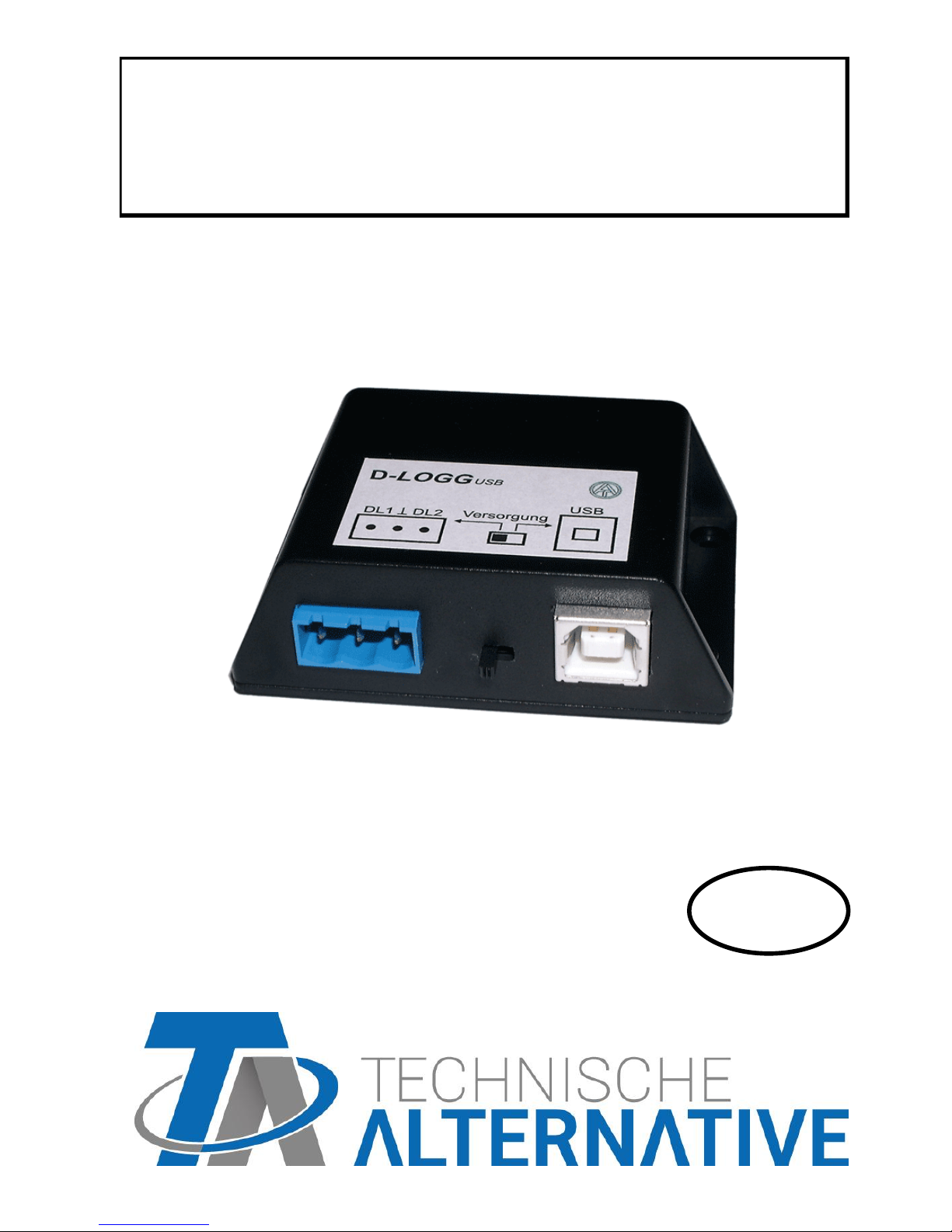
D-LOGG
Version 2.9 EN
Manual version 2
Data converter
Operation
Winsol
Memory Manager
en
Page 2

2
Page 3

3
Table of contents
Hardware / General information ........................................................................................... 4
Power Supply / Slide Switch ................................................................................................ 4
Data line .............................................................................................................................. 4
USB Interface ...................................................................................................................... 5
Software .................................................................................................................................. 5
Installation ........................................................................................................................... 5
Uninstalling .......................................................................................................................... 5
USB driver .............................................................................................................................. 6
Installation ........................................................................................................................... 6
Configuring the virtual COM port ......................................................................................... 7
Winsol (from version 2.03) .................................................................................................... 8
General toolbar .................................................................................................................... 8
Language............................................................................................................................. 8
Basic settings ...................................................................................................................... 8
Setup dialogue ..................................................................................................................... 9
Current measured values .................................................................................................. 13
Customer mode ................................................................................................................. 14
Add new customer ......................................................................................................... 14
Open customer .............................................................................................................. 14
Manage customer .......................................................................................................... 14
Recording of measured values from a customer system ............................................... 15
Read out logger data ................................................................ ................................ ......... 15
Reading out from devices without a timestamp ............................................................. 16
Autostart ........................................................................................................................ 17
Delete logger data ............................................................................................................. 17
Measured value diagram ................................................................................................... 18
Toolbar measured value diagram ...................................................................................... 18
Navigation methods ........................................................................................................... 19
Export ................................................................................................................................ 24
Memory Manager (from version 2.07) ................................................................................ 25
Operating System Update ................................................................................................. 26
Troubleshooting .................................................................................................................. 27
Page 4
4
Hardware / General information
Power Supply / Slide Switch
When the data converter is connected to at least one controller (DL), the slide switch on the
converter must be in the "DL" position (left)!! Otherwise, problems with data logging can
occur. The data converter receives the power it requires from the controller, regardless of
whether it is connected to a PC or not.
Bus load (DL-bus) = 24%
If the data converter is not connected to any controller, the slide switch for communication
with the PC must be in the "USB" position (to the right), so that the converter is supplied
with power via the USB connector.
The recorded data is saved to internal memory every hour, where it is retained even when no
power is present. This means that a power loss will result in a maximum loss of the last hour
of data.
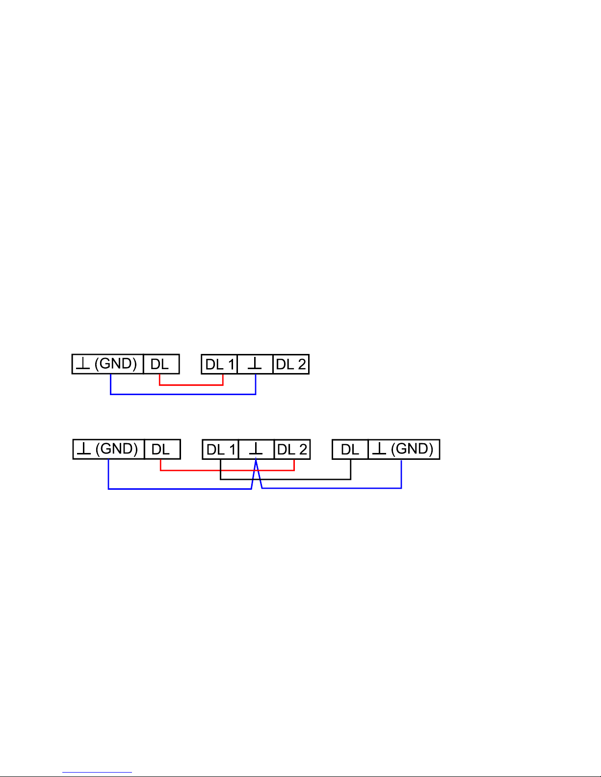
Data line
Every UVR controller has a data line output DL (with the EEG30, TFM66 D0) that, together
with the (sensor) ground conductor, forms a two-conductor cable. The data converter has 2
data line inputs for simultaneously recording measured values from up to two controllers.
Connection 1 controller:
Controller
D-LOGG
Connection 2 controllers:
Controller 1
D-LOGG
Controller 2
Any cable with a cross section of 0.75 mm² can be used for the data link (e.g. twin-strand)
having a max. length of 30 m. For longer cables, we recommend the use of shielded cable. If
the data from two controllers is to be acquired by the data converter, then separate shielded
cables must be used to provide protection against crosstalk errors. The data conductors must
never be in the same cable as the CAN bus.
Page 5

5
NOTE:
With the UVR1611 controller, output 14 (DL) can be used as both a data connection and
a control connection. For data logging, output 14 must therefore always be configured as
data line via the "Outputs" menu.
UVR1611 – Controllers from version A2.16 additionally allow network input variables to
be logged (NETW.IP.=>DL.: yes), which is then handled by the D-LOGG as a second virtual UVR1611. Logging of network variables is thus not possible when two physical controllers are connected to the data converter.
The D-LOGG requires more operating current than the EEG30 and TFM66 devices can
supply. When setting up a data connection between an EEG30 or TFM66 and the DLOGG data converter, an additional 1 kOhm resistor must be installed between the D0
and the Plus power supply terminal of the EEG30 or TFM66.
Logged data is lost when the number of data connections or the controller type is
changed!
USB Interface
The USB interface (slide switch in the "DL" position) does not represent an electrical connection between the data converter and the PC. For reasons of safety, it is electrically isolated
via optocouplers.
In the "USB" position, the slide switch creates an electrical connection to provide power for
the data converter from the PC. For this reason, the slide switch may only be set to the
"USB" position when no connection to a controller exists.
For communication between the PC and D-LOGG, a special driver is also required that creates a virtual COM interface in the PC, which is then used by the Winsol or Memory Man-
ager programs to access the data converter. See also the chapter "USB driver".
Software
Installation
The latest versions of the software are available for downloading at http://www.ta.co.at and
they overwrite the existing software without losing any previously stored data. However, it is
recommended to uninstall the existing versions of the software before installing new versions.
This only then removes the application and all data created with the application is retained.
CAUTION: Newer software versions are not always compatible with the version of the converter operating system. The homepage provides information on this. It may be necessary to
also upgrade the data converter operating system (see "Memory Manager").
Uninstalling
The programs can be uninstalled using the <add/remove programs> function in the Windows
control panel.
Windows XP: … Control Panel Software (add or remove programs)
Windows Vista, 7: … Control Panel Programs and Functions
Windows 8: Move the mouse pointer into the left, bottom corner Right mouse button
Programs and Features
Page 6

6
USB driver
The USB driver is required for USB communication between the PC and D-LOGG and it creates a virtual COM port on the PC for this purpose.
The driver must be installed on the PC for this (see "Installation") and is automatically loaded when a D-LOGG is connected to the PC.
The required drivers can be installed from the homepage http://www.ta.co.at or also via Windows Update.
Installation
When a D-LOGG is connected to the PC with a USB cable, the PC automatically recognises
a new hardware component and automatically starts the "Hardware-Assistant" (Hardware
Wizard) if a driver has not yet been installed for this device.
If an Internet connection is available, Windows connects automatically to the Windows Update website to install a suitable driver. In this case no further steps are necessary.
If an Internet connection is not available, or no suitable driver has been found or if Windows
is configured to prevent the automatic installation of drivers, the required drivers can be manually installed.
If the Wizard does not start automatically, the installation can also be manually started. When
the device is connected to the PC but the driver has not been installed, it is displayed in the
Windows device Manager) with an exclamation mark in one of the <other devices>, <Ports
(COM and LPT)> or <USB Controller> lists. The driver installation can be manually started
from here.
For more detailed information please see the USB-drivers manual under http://www.ta.co.at.
Page 7
7
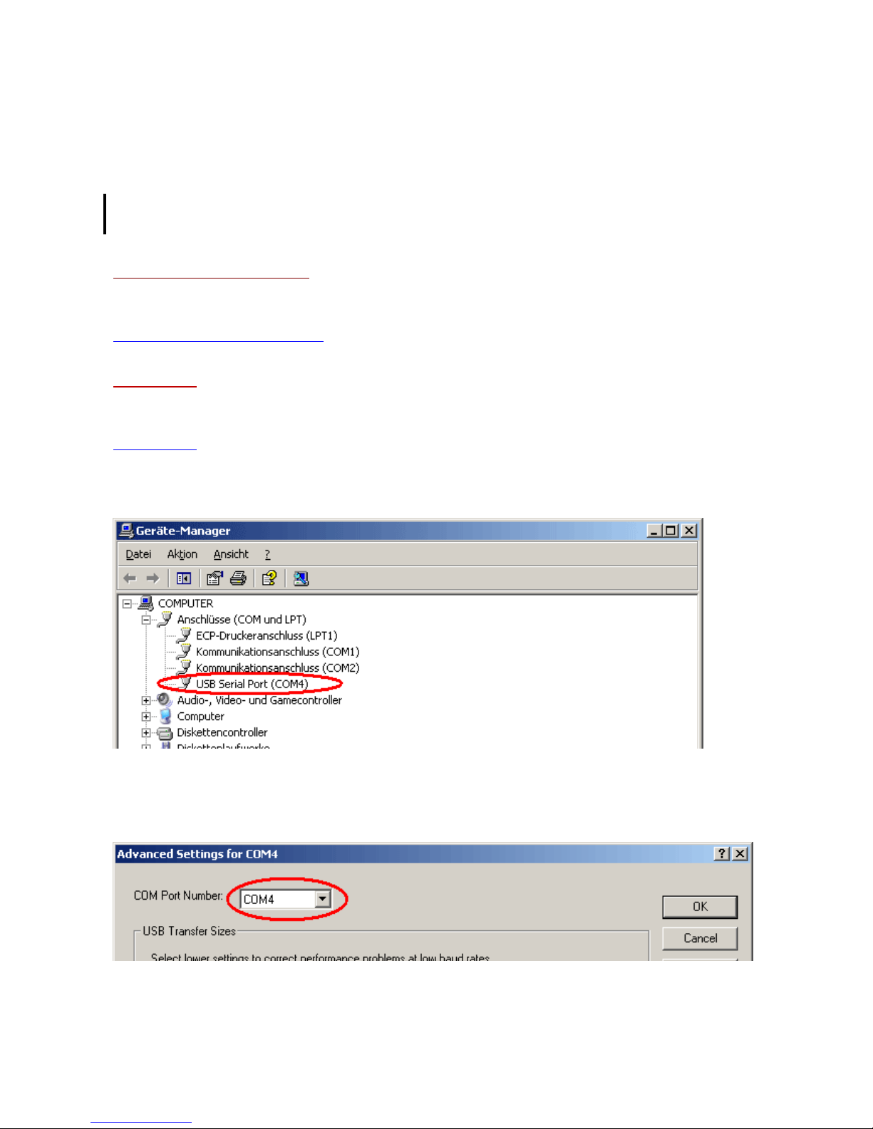
Configuring the virtual COM port
Memory Manager supports COM ports COM1 – COM6. If the virtual COM port that has been
allocated to the driver during installation is not supported by Memory Manager, the driver
can be manually allocated to another, still available port. For a PC with an internal modem, it
should be noted that COM3 is usually used for this modem.
The D-LOGG must be connected to the PC in order to configure the virtual COM port in the
Windows Device Manager.
Windows XP (classic view):
Start Settings Control Panel System Hardware Device Manager Ports (COM
and LPT)
Windows Vista (classic view):
Start Settings Control Panel Device Manager Ports (COM & LPT)
Windows 7:
Start “Systemsteuerung“ (control panel) Hardware and Sound „Gerätemanager“ (de-
vice manager) “Anschlüsse“ (ports) (COM&LPT)
Windows 8:
Move the mouse pointer into the left, bottom corner Right mouse button Programs and
Features
The driver can be assigned a different COM port in the properties of the <USB Serial Port>:
USB Serial Port Properties Port Settings Advanced…
Page 8
Winsol
8
Winsol (from version 2.03)
The Winsol program is used for the acquisition and evaluation of measured values recorded
by the data logger.
To be able to capture the data from several systems or data loggers, Winsol enables the
creation and management of "Customers".
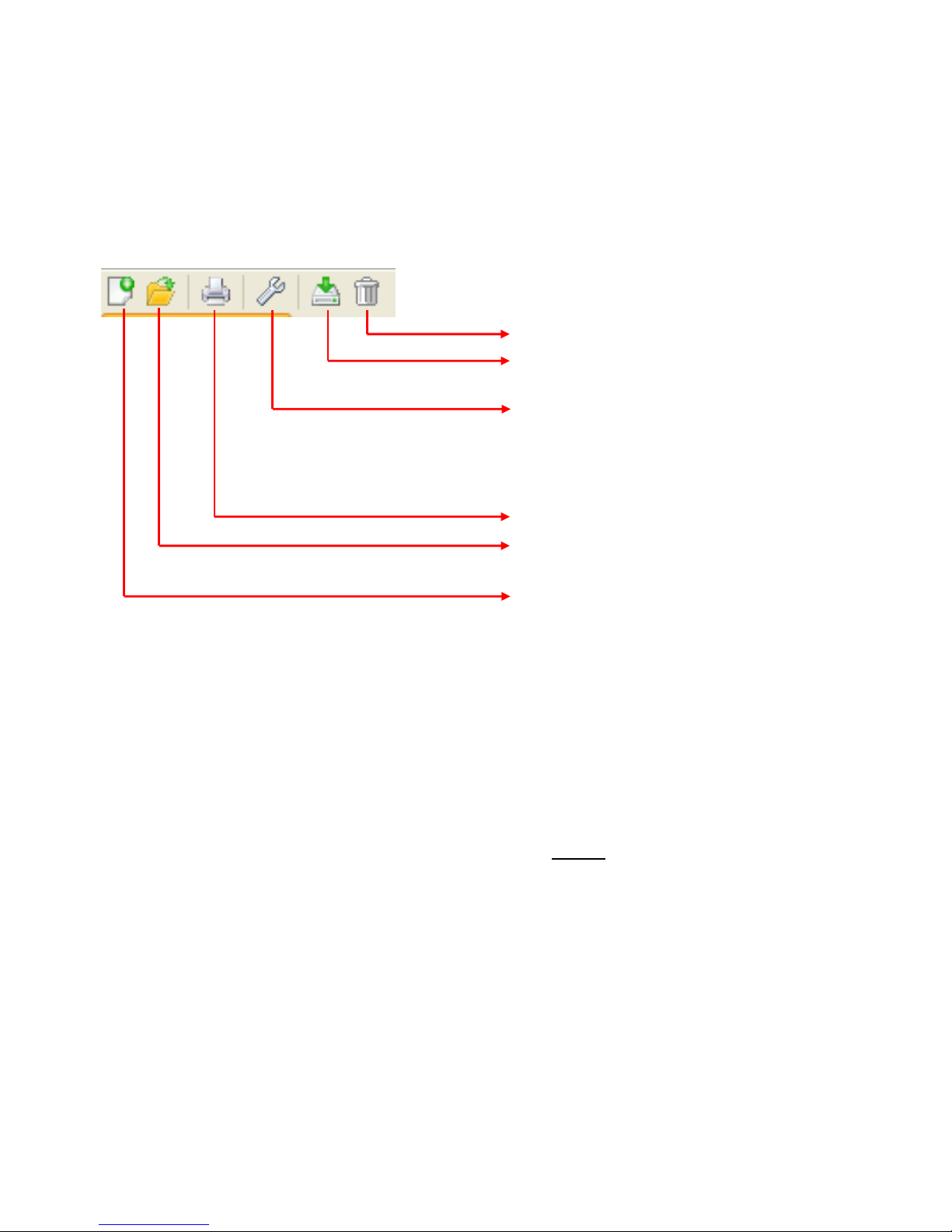
General toolbar
Deletes the logger data store
Reads the data stored in the logger
Setup - Selection of the data logger, interface, specification of the logger configuration and entry of the device description and the logged values.
Prints the displayed graphic
Opens an existing customer folder
Creates a new customer folder
Language
A number of languages are available for selection. Select menu "Optionen \ Sprache" (Options\Language) and click on the desired language. Winsol must be restarted for the language choice to come into effect.
Basic settings
The Winsol data path can be changed in the menu "Options \ Basic settings...". The
standard setting is the Winsol installation path (e.g. C:\Programs\Technische Alternative\Winsol). We recommend creating a data path outside the program folder. Already existing data must be manually copied into the new data path, before the setting is changed in
Winsol and new data read in from the logger!
Procedure for transfer of existing data into a new data path:
1. Create new data path (e.g. using Windows Explorer).
2. Copy the existing files and folders from the existing data path (e.g. installation path
"C:\Programs\Technische Alternative\Winsol\") in to the new path.
3. In the Winsol basic settings, set the new path as a data path.
Page 9
Winsol
9
Setup dialogue
Selection of the data logger, interface, specification of the logger configuration and entry of
the device description and the logged values takes place in the menu "File \ Setup".
"Next" is used to switch forward to the next setup window, while "Cancel" is used to cancel
setup without changing the logger configuration.
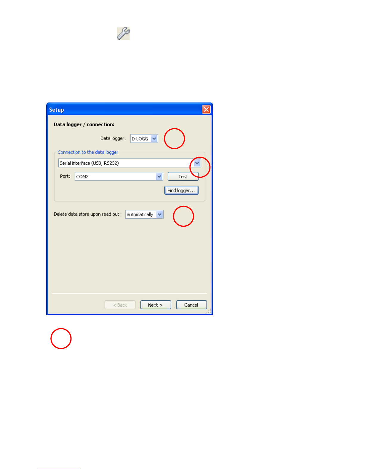
1. Window: Data logger/connection
Summary:
Selection of the data logger:
D-LOGG
Selection of the connection to the
data logger: Serial interface (USB,
RS232)
Selection of how the data store
should be deleted:
automatically or manually
Selection of the data logger
The data logger type can be specified here.
1
1
2
3
Page 10
Winsol
10
Selection of the connection to the data logger
As the D-LOGG has no Ethernet interface, only the serial interface
is enabled for selection of the COM port.
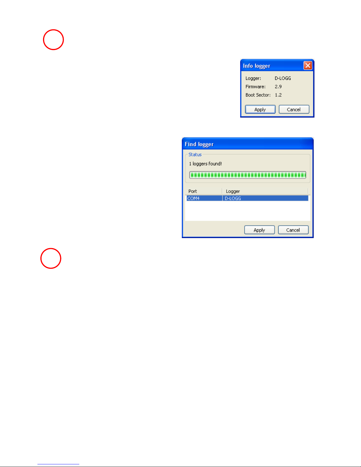
"Test" checks communication with the logger at the selected interface. Information about the connected logger is displayed. "Apply"
is used to specify the logger type in Setup.
If the COM port is not known, "Find logger" is
used to search all the COM interfaces of the
computer for connected loggers.
The COM port and type of the logger found
are displayed. "Apply" is used to set the highlighted logger type in setup.
Clearing the data store
2 options are available:
automatically After reading out of the memory, it is automatically deleted (recommended).
manually After reading out of the memory, a query is displayed asking whether the
memory should be deleted.
It is recommended that the logger data store is deleted after successful read-
ing out.
3
2
Page 11

Winsol
11
2. Window: Data recording
Summary:
Reading out of the configuration
stored in the logger
Specification of the Source and
number of data links
Specification of the device types,
Selection of the saving criterion
Overwriting of the configuration in
the logger
The changed settings are
only saved and transferred as a configuration
to the logger if this button is clicked.
Source: DL (data link)
The parameters contained in the data records (devices) are firmly specified in this process.
Up to 2 data records (devices) can be recorded.
The number of devices to be logged is given under "Number".
The logged devices are then selected by double clicking in the respective fields. An ESR31
controller is selected as an "ESR21", UVR63 and UVR63H controllers are selected as
"UVR61-3".
If under Output 14 of the UVR1611 "NETW.IP.=>DL.:" is set to "yes", the measured values
from the network inputs are output as a 2nd device on the DL-Bus. If "NETW.IP.=>DL.:" is
switched from "yes" to "no", the data logger must be briefly switched off (no power supply)
so that it can reinitialise itself.
Saving criterion
The saving criterion is used to specify
when the data logger is to save a pointin-time with all captured measured values.
Two criteria are optionally available for
data logging.
Time interval
Entry of a time interval between 20 seconds and 40 minutes is possible.
Page 12

Winsol
12
Temperature difference
For fault analysis, a saving criterion of 3.0K is recommended. Each time a temperature
measured value changes by more than 3.0K or an output status changes, a "Measured
value point-in-time" is saved. In this respect the maximum time resolution is 10 seconds.
Adjustment range: 0.5 – 12.0K
Memory capacity
The maximum number of points-in-time that the data logger can store depends on the type
and number of controllers to be recorded.
Max. number of points-in-time
(Data logging using the DL-bus)
Controller type:
With 1xDL:
With 2xDL:
UVR1611,
UVR61-3,
UVR63, UVR63H
8000
4000
ESR21
ESR31
16000
8000
All others
32000
16000
A memory overflow leads to overwriting of the oldest data.
3. Window: Measured value descriptions
A device description and descriptions for the measured values can be specified for all devices.
Summary:
Selection of the device
Device description
Description of the analog and digital values
Conclusion of the setup process by clicking
OK
Important: Setup is only completed if the "OK" button has been clicked.
Page 13

Winsol
13
Current measured values
In this tab, the actual measured values of the devices linked to the data logger are displayed
in tabular format.
The tab "Current measured values" is the quickest and simplest option for testing the "Controller data logger" data connection.
Each data record (device) is displayed in its own view. The selection is made using a selection box in the top part of the window.
The point-in-time of the displayed measured values is shown in the bottom part of the window
(last update). The time shown here corresponds to the computer's time. The duration to the
next display update is likewise displayed.
Example:
Page 14

Winsol
14
Customer mode
Winsol not only permits the management and analysis of its "own data", rather it also makes
possible the analysis of system-external data. This is an important tool for the technician
where function monitoring and troubleshooting of customer systems is concerned.
Add new customer
New customers can be added in the menu "File \ New…". A new folder
is created in the Winsol file system for each customer, in which the corresponding configurations and log files are saved. The directory "Info-
sol" in the Winsol data path contains all these customer folders.
There is also an option of transferring the setup settings of another customer.
After creation of a customer the Setup settings must be set.
The currently selected customer is displayed in the Winsol title bar. If no
customer description is shown in the title bar, the "own data" are selected.
Open customer
An already created customer can be opened in the menu "File \
Open...".
Manage customer
Customers can be renamed or deleted via the menu "File \ Manage...".
Page 15

Winsol
15
Recording of measured values from a customer system
There are three options for recording the measured values from a customer system:
a) The data logger is installed by the system and regularly read out locally by the service
technician using a notebook.
b) If the customer himself records the measured values from his system, then he can
forward the log files to the technician by email.
c) If the reading out of the recorded data is not possible locally, the measured values
can be recorded as follows:
Preparation for data recording:
1) Connect the data logger to the PC, without a DL cable and with the slide switch in
the "USB" position.
2) In Winsol create a customer for the data to be recorded and select.
3) Specify the desired configuration in setup and overwrite at the data logger.
4) Move the slide switch to the "DL" position.
Data acquisition at the customer:
5) Connect the data logger to the controller (observe polarity!). With a UVR1611, data
output via the DL-bus must be activated (output 14 defined as "data link").
6) As long as the data logger is connected to the controller, the measured values are
recorded according to the selected save criterion.
7) When disconnecting the data logger from the controller, date and time must be noted, because Winsol needs these so that when reading data in, the correct time can
be allocated to it. This is not necessary with the UVR1611, UVR61-3, UVR63 and
UVR63H.
Reading out of the recorded data:
8) Connect the data logger to the PC, without a DL cable and with the slide switch in
the "USB" position.
9) Select the corresponding customer in Winsol.
10) The data stored in the data logger can now be read in with "Read out logger data"
and then analysed.
11)
Read out logger data
Reading out of the logger data is started in the menu "Logger \ Read out data".
The data recorded and stored in the Bootloader are read out and saved as a log file in the
Winsol file system on the PC. A log file is produced for each month in the corresponding
sub-directory ("...\log"). When data logging from two or more data records (devices) Winsol
saves its data in the sub-directories "…\log1" and "…\log2" etc.. The file name of a log file
contains information about the year and month of the contained data. For example, the file
"Y201210.log" contains the measuring data saved in October 2012.
Warning: If the data of several systems are recorded, then before the data is read in, it must
be ensured that the correct "Customer" (see Customer mode) is selected!
Page 16

Winsol
16
Reading out from devices without a timestamp
Devices without a timestamp are the following:
EEG30, ESR21, ESR31, HZR65, TFM66, UVR31, UVR42 and UVR64.
These devices do not have an internal clock with time and date.
When reading out from these devices, a differentiation is made as to whether the data logger
remains connected to the device or not during reading out.
1. The logger is connected to the device
In this case the PC time is taken as the reading out point-in-time.
2. The logger has been disconnected from the device.
Winsol now requests entry of the point-in-time at which the disconnection occurred.
3. Interruption of data recording
If logging has been interrupted by a loss of power at the logger, Winsol cannot allocate the
values logged prior to the power failure to a particular time.
"Discard data" means that all data prior to the power failure are discarded, and only the data
after the interruption are evaluated by Winsol.
If the display of all data is required and correct time allocation is not relevant, the duration for
the interruption of recording can be entered, with the assumption that the data are to be processed by Winsol.
Page 17

Winsol
17
1
Autostart
An automatic reading out of the data when booting the PC
can be implemented using the options in the menu "Options \
Autostart".
Selection of the customers that are automatically read out when booting the PC.
The logger data store is then deleted if in the
customer setup, delete has been set to automatic or manual.
Autostart - Export to csv file
After reading out of the data, csv files are au-
tomatically created in the selected format.
These files are saved in the folder <Data
path>\Infosol\Customer\csv. Existing files are overwritten.
Shut down computer
This option is also possible. Here, as the PC boots up, the data are automatically
read in (incl. possible csv conversion) and then the PC shutdown after the subsequent countdown.
This function is intended for computers that are used solely for data acquisition. In this case,
the PC must be automatically booted in a time-dependent manner. For example, this is possible using an external time switch, which supplies the computer with power in a timedependent manner and if the appropriate BIOS settings have been made (bootup, if supply
voltage applied).
Delete logger data
Using the menu "Logger \ Delete data", the data stored in the logger can be manually deleted.
1
2
2
Page 18

Winsol
18
Cursor
Measured value diagram
This window presents the recorded data (log files) over the course of the day.
Optimum display of the graphic is possible using the comprehensive adjustment and operating options. A maximum 16 analog and 16 digital values from all the logged values can be
displayed simultaneously. The menu option "Manage profiles" is used to select the values to
be displayed and the colour of the curves. Moreover independent profiles can be created,
modified or deleted for various system areas.
Actual example of a system (1 controller, 2 data records):
Toolbar
Digital values (on/off)
Analog values
Date, time and
measured values
for the cursor po-
Page 19

Winsol
19
Toolbar measured value diagram
Navigation methods
There are various options and methods, for optimally configuring or changing the graphics
display to meet your individual requirements.
Navigating in the graphic takes place using keyboard and mouse commands that are listed in
the following tables:
Shifting the display window
Navigation
Keyboard
Mouse
Shifting the display window
along the X-axis (only possible, if the time axis displays
less than 24 hours)
Only with the cursor hidden:
← and →,
Shifting by 1/48 of the display
window per key press
Move the mouse with the
right mouse button depressed
Shifting the display window
along the Y-axis
Page up and Page down
Shifting by 1/40 of the display
window per key press
Move the mouse with the
right mouse button depressed
X-axis zooming
Navigation
Keyboard
Mouse
X-axis zooming (+)
z
The fixed point is the position
of the cursor (if activated) or
the middle of the diagram
Scroll "forward" (fixed point is
the position of the mouse
pointer), or button on the
toolbar (fixed point is the cursor position (if activated) or
the middle of the diagram)
X-axis zooming (-)
u
The fixed point is the position
of the cursor (if activated) or
the middle of the diagram
Scroll "back" (fixed point is
the position of the mouse
pointer) or button on the
toolbar (fixed point is the cursor position (if activated) or
the middle of the diagram)
Manage profiles
Profile display
Measured values scaling
Cursor on/off
Grid on/off
Select day (calendar)
Previous month
Previous day
Next day
Next month
Zoom in time axis
Zoom out time axis
Auto scaling
Y-axis
Standard scaling
Y-axis
Page 20

Winsol
20
Y-axis zooming
Navigation
Keyboard
Mouse
Y-axis zooming (+)
Ctrl + z
Fixed point is the middle of
the diagram
Scroll "forward" + pressed
Ctrl key
Fixed point is the position of
the mouse pointer
Y-axis zooming (-)
Ctrl + u
Fixed point is the middle of
the diagram
Scroll "back" + pressed Ctrl
key
Fixed point is the position of
the mouse pointer
Zooming in X- and Y-axes (simultaneously)
Navigation
Keyboard
Mouse
Zoom in X- and Y-axis (+)
-
Zoom window with depressed left
mouse button (see figure)
Zoom out X- and Y-axis (-)
-
Negative zoom window with depressed left mouse button (see
figure)
Example: Zoom in (draw zoom Zoom out (draw zoom
window from top left to bottom right) window from bottom right to top left)
Page 21

Winsol
21
Move cursor in X-axis
Navigation
Keyboard
Mouse
Set cursor
-
Double-click with left mouse
button (positioning at the
closest measuring point)
Measuring point / step forward
→
Measuring point / step back
←
-
min. 1/24 of the display pane
/ step forward
Ctrl + →
-
min. 1/24 of the display pane
/ step back
Ctrl + ←
-
1 day / step forward
↑
Toolbar:
1 day / step back
↓
Toolbar:
1 month / step forward
Ctrl + ↑
Toolbar:
1 month / step back
Ctrl + ↓
Toolbar:
Start day
Pos1
-
End day
End
-
Start recording
Ctrl + Pos1
-
End recording
Ctrl + End
-
Other functions
Navigation
Keyboard
Mouse
Hide cursor
c
Toolbar:
Auto-zoom in Y-axis
a
Toolbar:
Standard-zoom in Y-axis
s
Toolbar:
Grid hide/show
g
Toolbar:
Press (print dialogue)
Ctrl + p
Menu bar:
Page 22

Winsol
22
Highlighting or hiding graphs
Clicking a measured value in the right table with the left mouse button causes the value and
graph to be especially highlighted.
Clicking a measured value in the right table with the right mouse button causes the value
and graph to be hidden.
Clicking again causes the highlighting or hiding to be cancelled.
Example:
Display of non-logged times
If there is less than 1 whole day between the logged data records, then the last measured
point is linked to the first measured point for a particular sensor by a straight line.
If there is more than 1 whole day between the logged data records, then dashed lines are
displayed.
If a day is selected from the calendar in which no values were logged, then the diagram
remains empty, therefore no dashed lines are displayed.
Highlighting of Ana1/1 and Ana2/1 by left clicking
Hiding of Ana9/1 by right clicking
Page 23

Winsol
23
Measured values scaling
This menu option is used for matched scaling of various measured value units.
This improves the perceptibility of measured values in the graphic.
Grid on/off
Makes possible the display and hiding of the grid.
Cursor on/off
If the cursor is switched off, no measured values are listed on the side and at the top right
only the date of the displayed day is henceforth displayed.
Select day
Calendar for selection of the day displayed.
Navigation
Navigation forwards or backwards in the data recording by a day or month.
Here only days are displayed, on which measured values have been recorded. I.e. days
without any data are jumped over.
Time axis zooming
Extending or shortening of the time axis (display pane: min. 30 minutes, max. 24 hours). The
fixed point is the position of the cursor (if activated) or the middle of the diagram.
Y-axis scaling
For optimum representation clicking "Auto-scaling Y-axis" causes the Y-axis scale to be
matched to the values.
Clicking "Y-axis standard scaling" causes the scaling to be reset to the default values that
were set in the profile.
Page 24

Winsol
24
Manage profiles
The menu option "Manage profiles" (Manage profiles) is used to select the values to be displayed and the colour of the graph curves. Moreover independent profiles can be created,
modified or deleted for various system areas and a separate diagram title specified.
Export
In this menu, the log files can be converted into *.csv file format for further processing with
any spreadsheet program. In this way you can create your own graphics and statistics with
the recorded measuring data.
Selection of the
displayed
profiles
Add new profile
Delete all profiles
Delete profile
Clear the selection of
graphs in the profile
Page 25

Memory Manager
25
Memory Manager (from version 2.07)
The Memory Manager program can be used to update the operating system of the data
converter. All other functions of the Memory Manager are not used with the D-LOGG.
Operating system update
Setup contains the settings which are necessary for correct communi-
cation between the PC and the D-LOGG.
Save the set interface parameters
Using the command " TEST COM " it is possible to carry out an automatic
search of the data converter for COM-interfaces supported by the Memory
Manager (connection via USB) independent of any setup settings.
Selects the default directories
Memory Manager language selection
The remaining buttons are not applicable to the data converter.
Page 26

Memory Manager
26
Operating System Update
The D-LOGG data converter has the same operating system (*.frm) as the BL232 Bootloader, which can be downloaded from the homepage at http://www.ta.co.at.
CAUTION: Newer operating systems are not necessarily compatible with the software already present on the PC. The homepage provides information on this. The software on the
PC should always be brought up to date before an operating system update.
It is advisable to read out any logged data before updating the operating system.
All program elements required for the system update are stored in a protected storage area
(boot sector) that cannot be overwritten by the data converter. This means that interrupting
the operating system transfer should not cause any problems. However, the device will not
operate correctly until the operating system is fully loaded. In general, an update should only
be performed when the newer operating system contains changes that are required (Never
change a running system!). An operating system update always represents a certain small
risk.
Page 27

Memory Manager
27
Troubleshooting
Serial interface (USB, RS232): The data logger is not recognised during "Test" of
Winsol.
1. Ensure that the data logger is connected to the PC via a USB connection.
2. If no controller is connected to the D-LOGG, then its slide switch must be in the "USB"
position.
3. Check in the Windows Device Manager whether the USB driver has been correctly in-
stalled (Device Manager Ports (COM and LPT)). In this case, its virtual COM port
appears in the list as "USB Serial Port".
3.1. If the driver has not yet been correctly installed, carry out the installation again
(see Chapter "USB driver \ Installation").
4. If the data logger is provided with at least one controller, check the data transfer from
the controller to the data logger (see the next point).
Data transfer from the controller to the data logger is not working.
(No measured values are displayed in the "Current measured values" of Winsol.)
1. Make sure that the data logger is connected to the controller and the slide switch is in
the "DL" position.
2. Check the connections and in particular ensure the polarity is correct.
3. With the UVR1611, data output must be activated if logging over the data link (DL-bus)
is to take place (output 14 defined as "data link"). On controller UVR16x2, data output
must be enabled in “DL settings” in the menu “DL bus”.
4. If several controllers are recorded using the data logger, check the data connections
individually to limit the problem. To do this, connect the data link (DL-bus) or CAN bus
as appropriate to the other controllers. When doing so it is important that the data link
is connected directly to the controller and not to the data input of the data logger, as
otherwise you will not receive useful results!
4.1. If data transfer functions over the DL-bus with each controller individually, then
the cause of the error is crosstalk between the two data links of the DL-bus. In
this case the two data links must be routed separately or at least one data link
must be routed in a shielded cable.
5. To limit the cause of the error during data transfer to a single data link, carry this out
as a test over a short cable (< 1 metre).
5.1. If data transfer functions over the short cable, then the error cause could be
crosstalk caused by an external interference source in the data link (DL-bus). In
this case, the data link must be routed in another way or a shielded cable must be
used.
6. If, in spite of the testing of all listed points, incorrect behaviour still exists, please contact your dealer or contact the manufacturer directly. However the cause of the fault
can only be found if a precise description of the fault is provided!
Page 28

Memory Manager
28
The data are recorded with an incorrect timestamp (date, time).
1. As when data logging with the VR1611 or UVR61-3 the timestamp is generated by the
controller, in this case the time indication in the controller must be corrected.
Warning: To be able to ensure a higher time resolution, the data logger synchronizes
with the controller during start-up and as a consequence updates its internal
timestamp. Therefore the data logger must be switched off (zero volts state) for a few
seconds after changing the time settings in the controller (pull out the DL bus), so that
it immediately synchronises itself after the restart.
2. When data logging using controllers without an internal time, the time or the point-intime at which the data logger was disconnected from the controller is taken from the
PC, so that the time can be allocated to the recorded data.
The csv files are not displayed in the corresponding data path "C:\Programs\..." or
the searched for subdirectory itself does not even exist.
Under certain circumstances, under Windows 8, Windows 7 and Windows Vista, the
files are saved under a user-specific "virtual program path":
C:\Users\<USERNAME>\AppData\Local\VirtualStore\Programs\Technische Alternative\Winsol\...
The folder "AppData" is not displayed as a matter of course and must therefore be entered manually in the Input field.
This takes you to the searched for files.
It is generally recommended that the Winsol data path is chosen outside the Program
folder (default installation path) (see Chapter "Basic Settings").
Subject to technical modifications without notice. © 2015
Page 29

EU Declaration of conformity
Document- Nr. / Date:
TA17014 / 02/02/2017
Company / Manufacturer:
Technische Alternative RT GmbH
Address:
A- 3872 Amaliendorf, Langestraße 124
This declaration of conformity is issued under the sole responsibility of the manufacturer.
Product name:
D-LOGG
Product brand:
Technische Alternative RT GmbH
Product description:
Data converter
The object of the declaration described above is in conformity with Directives:
2014/35/EU
Low voltage standard
2014/30/EU
Electromagnetic compatibility
2011/65/EU
RoHS Restriction of the use of certain hazardous substances
Employed standards:
EN 60730-1: 2011
Automatic electrical controls for household and similar use –
Part 1: General requirements
EN 61000-6-3: 2007
+A1: 2011
+ AC2012
Electromagnetic compatibility (EMC) - Part 6-3: Generic standards Emission standard for residential, commercial and light-industrial environments
EN 61000-6-2: 2005
+ AC2005
Electromagnetic compatibility (EMC) - Part 6-2: Generic standards Immunity for industrial environments
EN 50581: 2012
Technical documentation for the assessment of electrical and electronic
products with respect to the restriction of hazardous substances
Position of CE - label: On packaging, manual and type label
Issuer:
Technische Alternative RT GmbH
A- 3872 Amaliendorf, Langestraße 124
This declaration is submitted by
Dipl.-Ing. Andreas Schneider, General manager,
02/02/2017
This declaration certifies the agreement with the named standards, contains however no warranty of
characteristics.
The security advices of included product documents are to be considered.
Page 30

Page 31

Page 32

Guarantee conditions
Note: The following guarantee conditions do not in any way limit the legal right to a guaran-
tee, rather expand your rights as a consumer.
1. The company Technische Alternative RT GmbH provides a two-year guarantee from the date
of purchase by the end consumer for all the devices and parts which it sells. Defects must be
reported immediately upon detection and within the guarantee period. Technical support
knows the correct solution for nearly all problems. In this respect, contacting us immediately
will help to avoid unnecessary expense or effort in troubleshooting.
2. The guarantee includes the free of charge repair (but not the cost of on site fault-finding, removal, refitting and shipping) of operational and material defects which impair operation. In the
event that a repair is not, for reasons of cost, worthwhile according to the assessment of
Technische Alternative, the goods will be replaced.
3. Not included is damage resulting from the effects of overvoltage or abnormal ambient conditions. Likewise, no guarantee liability can be accepted if the device defect is due to: transport
damage for which we are not responsible, incorrect installation and assembly, incorrect use,
non-observance of operating and installation instructions or incorrect maintenance.
4. The guarantee claim will expire if repairs or actions are carried out by persons who are not authorised to do so or have not been so authorised by us or if our devices are operated with
spare, supplementary or accessory parts which are not considered to be original parts.
5. The defective parts must be sent to our factory with an enclosed copy of the proof of purchase and a precise description of the defect. Processing is accelerated if an RMA number is
applied for via our home page www.ta.co.at. A prior clarification of the defect with our technical
support is necessary.
6. Services provided under guarantee result neither in an extension of the guarantee period nor
in a resetting of the guarantee period. The guarantee period for fitted parts ends with the
guarantee period of the whole device.
7. Extended or other claims, especially those for compensation for damage other than to the device itself are, insofar as a liability is not legally required, excluded.
Legal notice
These assembly and operating instructions are protected by copyright.
Use outside the copyright requires the consent of the company Technische Alternative RT GmbH.
This applies in particular to reproductions, translations and electronic media.
Technische Alternative RT GmbH
A-3872 Amaliendorf Langestraße 124
Tel ++43 (0)2862 53635 Fax ++43 (0)2862 53635 7
E-Mail: mail@ta.co.at --- www.ta.co.at --- © 2017
 Loading...