

Page 1
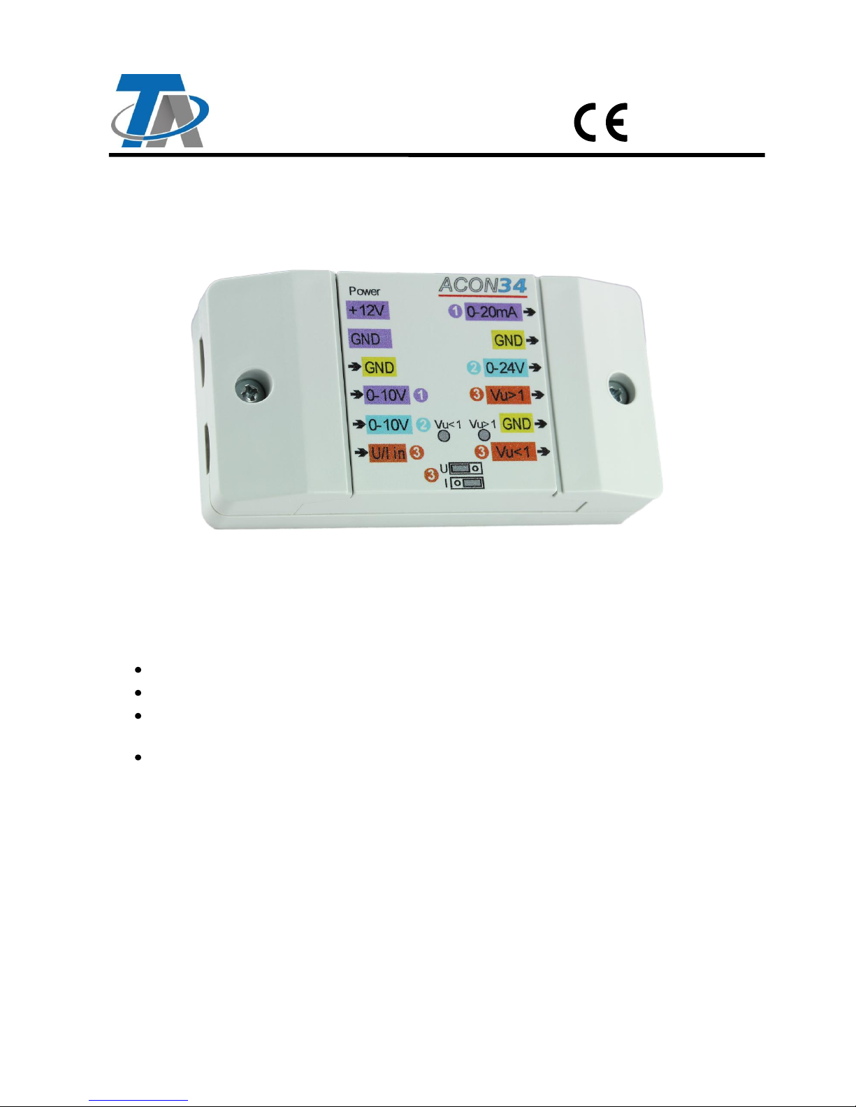
Analogue signal converter
This device has been designed to adjust signals between UVR controllers and third party
devices or industrial sensors.
It can be used to convert different signal levels or current into voltage and vice versa. Thanks
to input filters, PWM signals can also be converted into analogue values.
Conversion of 0-10 V signal into a 0-24 V signal
Conversion of 0-10 V signal into a 0-20 mA current
Freely usable level converter (input: 0-10 V or 0-20 mA), converts input into a voltage
signal with a transfer ratio that can be adjusted using two potentiometers and a jumper
Conversion of a PWM signal (500 Hz to 1 kHz/10 V) into a 0-10 V signal
ACON 34
Vers. 1.00 EN
Technische Alternative RT GmbH
A-3872 Amaliendorf, Langestr. 124
Tel +43 (0)2862 53635 mail@ta.co.at
Page 2
Power supply +12 V
The converter is supplied by the 12 V connection of a freely programmable controller or by an
external power supply unit (12 V).
Regardless of the connection, the PCB is protected against short circuits for one minute.
A resettable fuse (0.5 A) is installed internally upstream of the supply input.
With no output load, the device typically draws a standby current of 6 mA.
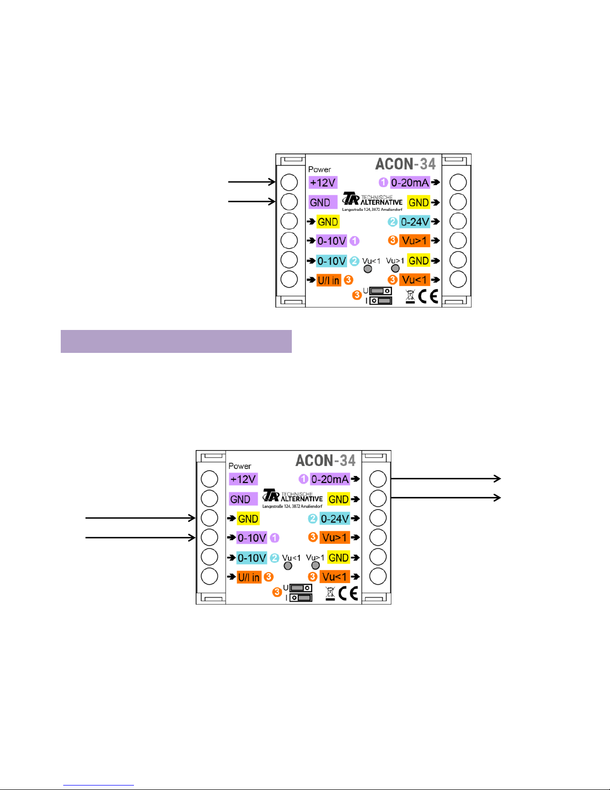
1. 0-10 V to 0-20 mA converter
In addition to the 0-10 V signal, a current of 4-20 mA is also a standard interface.
This level converter generates current that is proportional to the input voltage.
The minimum current of 4 mA is not generated and must be achieved by programming the
0-10 V source accordingly.
Accuracy +/- 0.5 mA
12 V DC
Power supply
Earth
0-10 V signal
0-20 mA signal
Earth
Page 3
2. 0-10 V to 24 V converter
Some boiler manufacturers use a 0-24 V signal in their products, which this converter
supplies.
Accuracy +/- 0.5 V at an internal resistance of the boiler controller of > 3 k
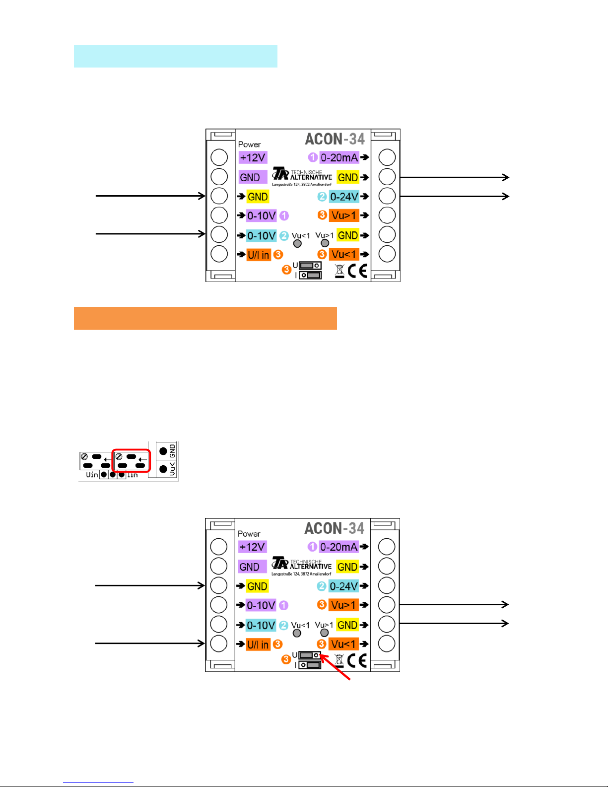
3. Freely adjustable level converter
The third input makes it possible to divide or amplify the input signal. The input signal can be
a 0-10 V voltage or 0-20 mA current (depending on jumper position); the output signal is
always a voltage.
3.1 Input signal – 0-10 V voltage
The jumper must be in position "U".
3.1.1. Voltage amplification
The output supplies 1 to 5 times the value of the input signal.
The amplification factor is set at the right-hand potentiometer. The
potentiometer setting must be established by taking measurements with
a multimeter.
Please note that the output signal is limited to approx. 25 V even at higher amplification
levels.
0-24 V signal
Earth
0-10 V signal
Earth
0-10 V signal
Earth
Earth
Voltage amplification
Jumper position "U"
Page 4

3.1.1. Voltage division
The output supplies 1 to 0.2 times the value of the input signal.
The division value is set at the left-hand potentiometer. The
potentiometer setting must be established by taking measurements with
a multimeter.
3.2 Input signal – 0-20 mA current
The jumper must be in position "I".
The input signal is issued as a multiple or divisor of the 2.2 V voltage
3.2.1. Current amplification
The output signal is 1 to 5 times the value of 2.2 V.
Example: Amplification by a factor of 5
A 20 mA input signal (maximum value) is issued as 5 times the 2.2 V voltage, i.e. as 11.0 V.
An input value of 10 mA would be issued as 5.5 V.
The amplification factor is set at the right-hand potentiometer. The
potentiometer setting must be established by taking measurements with
a multimeter.
Please note that the output signal can be greater than 10 V if amplified by a factor of 5.
Earth
0-10 V signal
Earth
Voltage division
Jumper position "U"
Earth
0-20 mA signal
Earth
Voltage amplification
Jumper position "I"
Page 5

3.2.2. Current division
The output signal is 1 to 0.2 times the value of 2.2 V.
Example: Division by a factor of 0.2
A 20 mA input signal (maximum value) is issued as one fifth of the 2.2 V voltage, i.e. as
0.44 V. An input value of 10 mA would be issued as 0.22 V.
The division value is set at the left-hand potentiometer. The
potentiometer setting must be established by taking measurements with
a multimeter.
PWM signals
All inputs have input filters which enable PWM signals to be captured. Instead of capturing
the 0-10 V voltage, the analogue converter can therefore also capture PWM signals and
issue them accordingly (0-20 mA, 0-24 V, Vu>1, Vu<1).
Example:
50 % PWM signal at input 3 (U/I in), jumper position "U", amplification = 1
-> output signal at output 3 Vu>1 = 5.0 V
Outputs
A maximum current of 20 mA per output is permitted. However, in the case of all outgoing
signal cables and voltage output jointly, the total load current must not exceed 40 mA. All
specifications provided only apply under this condition.
Earth
0-20 mA signal
Earth
Voltage division
Jumper position "I"
Page 6

Dimensions in mm
Technical data
Input resistance of all stages at 0-10 V
Approx. 50 k
Output impedance of all stages
50
Terminal area
Max. 1.5 mm²
IP rating
IP 40
Max. ambient temperature
45 °C
Subject to technical modifications © 2017
Top-hat rail installation
(support rail TS35 to
standard EN 50022)
Page 7

Page 8

Technische Alternative RT GmbH
A-3872 Amaliendorf Langestrasse 124, Austria
Tel ++43 (0)2862 53635 Fax ++43 (0)2862 53635 7
Email: mail@ta.co.at --- www.ta.co.at --- © 2017
 Loading...