

Page 1
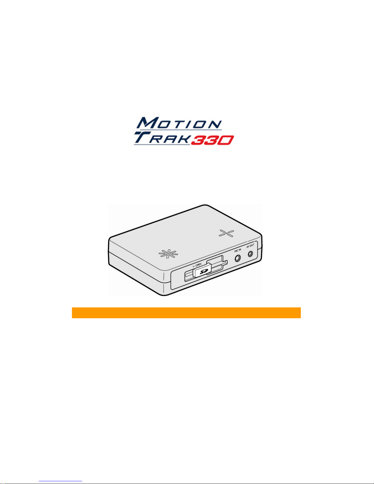
USER GUIDE
5
Edition
z
Before connecting and installing
this Drive Recorder
please
VER 2.0.1
h
z Thank you for purchasing this Drive Recorder.
z Before using the Drive Recorder, please ensure that you
read and understand this USER GUIDE.
z Please store this USER GUIDE in an easily accessible location.
refer to the appropriate instruction manual for proper operation.
,
Page 2

Page 3

FCC
This equipment has been tested and found to comply with the limits for a Class
television reception, which can be determined by turning the equipment off and
INFORMATION TO THE USER
B digital device, pursuant to part 15 of the FCC Rules. These limits are
designed to provide reasonable protection against harmful interference in a
residential installation. This equipment generates, uses and can radiate radio
frequency energy and, if not installed and used in accordance with the
instructions, may cause harmful interference to radio communications.
However, there is no guarantee that interference will not occur in a particular
installation. If this equipment does cause harmful interference to radio or
on, the user is encouraged to try to correct the interference by one more of the
following measures:
-Reorient or relocate the receiving antenna.
- Increase the separation between the equipment and receiver.
- Connect the equipment into an outlet on a circuit different from that to which
the receiver is connected.
- Consult the dealer or an experienced radio/TV technician for help.
WARNING
Any changes or modifications not expressly approved by the
manufacturer could void the user’s authority to operate the equipment.
3
Page 4

SAFETY ADVICE
CAUTION
NO USER
-
SERVICEABLE PARTS INSIDE
Battery for RTC(Real Time Clock) inside
automatically. Test and set your own G
Sensor level for your vehicle
RISK OF ELECTRIC SHOCK
DO NOT OPEN
CAUTION: TO REDUCE THE RISK OF ELECTRIC SHOCK,
DO NOT REMOVE COVER.
.
REFER SERVICING TO QUALIFIED SERVICE PERSONNEL.
Please make sure you follow the safety advice/instructions given in the user guide.
Caution
RISK OF EXPLOSION IF BATTERY IS REPLACED BY AN INCORRECT TYPE.
DISPOSE OF USED BATTERIES ACCORDING TO THE INSTRUCTIONS.
.
Caution
Install the product where it does not block driver’s visibility and where there is
no airbag installed. This could cause an accident or might injure the passengers in
case of accident.
Caution
Damages due to production malfunction, loss of data, or other damages occurring while
using this product shall not be the responsibility of the manufacturer. Although the
product is a device used for recording videos, the product may not save all videos in the
case of a malfunction. In the case of an accident, the sensor may not recognize the
shock when the impact is light and as a result it may not begin recording automatically.
Caution
When the impact is slight, such as a minor bump in the road, the G-Sensor
may not recognize the impact and as a result it may not begin recording
-
.
WARNING:
TO PREVENT FIRE OR ELECTRIC SHOCK HAZARD, DO NOT EXPOSE
THIS APPLIANCE TO RAIN OR MOISTURE.
4
Page 5

GPS Reception
pp
t
MP3
roadway or
parking area, inside a building or surrounded by high
-
rise
1. Activate the product in an area without large buildings
to improve GPS reception.
This commercial purpose GPS has an average range error of more
than 15 meters (49 ft)and the range error could be more than 100
meters (328 ft) due to environmental conditions like buildings,
roadside trees, etc.
2. The temperature range for optimum operation of this
GPS receiver in your car is -10 ~ 50°C (14 ~ 122°F).
3. When using the product for the first time or after a long
period of non use (more than three days), it may take a
little longer to recognize your current location.
It may take between five and thirty minutes to get GPS reception.
GPS reception may be impaired under the following circumstances.
1) If there is an object at the end of the GPS antenna.
2) If your vehicle has metallic elements on the windshields.
3) If equipment generating electromagnetic waves that interfere with the GPS
signal is installed in the vehicle e.g.: Other GPS devices such as a certain
ype of wireless activated alarms,
using GPS.
4) If you are using a receiver connected by cable, electric interference can be
avoided by simply changing the location of the receiver (antenna).
5) On heavily overcast or cloudy days, if the vehicle is in a covered location
such as under a bridge or raised roadway, in a tunnel, an underground
buildings.
6) If GPS signal reception is poor, it may take longer to locate your current
position when the vehicle is moving than when it is stationary.
and CD players and camera alarms
5
Page 6
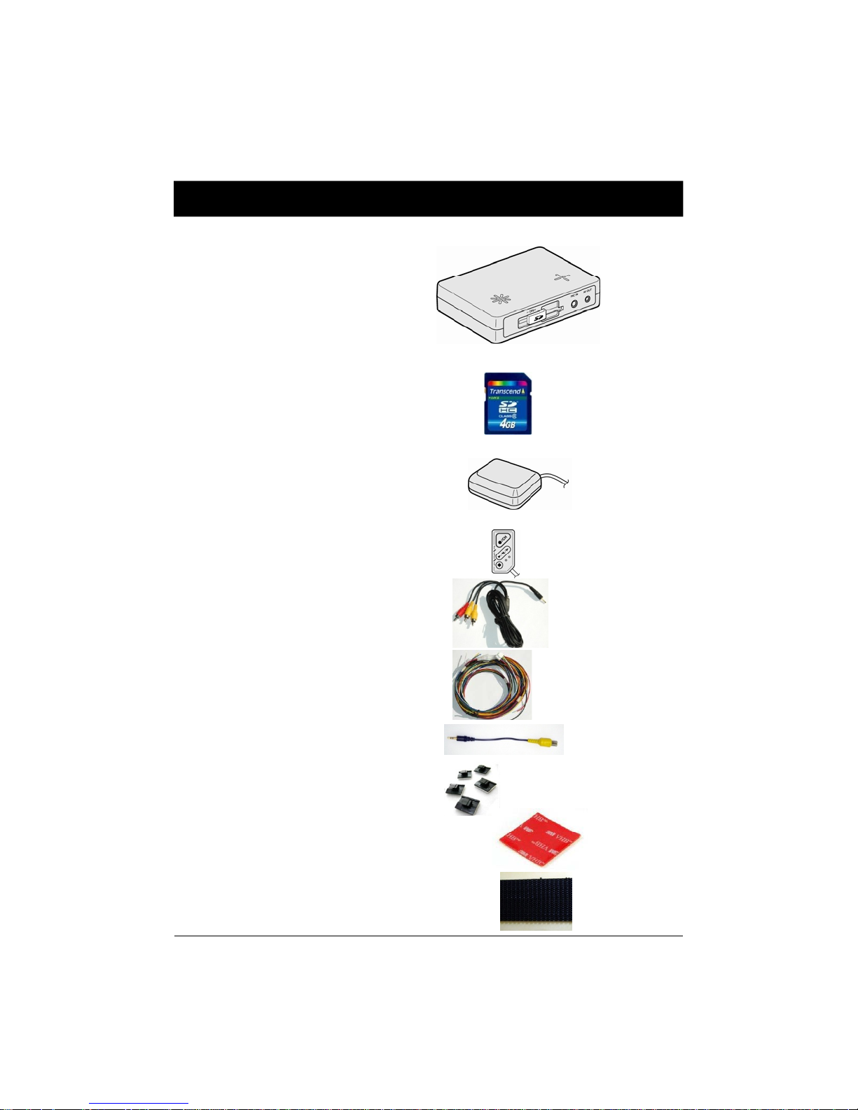
CONTENTS
in the provided SD card.)
You should have a set of the following items for each MotionTrak330 order.
1. MotionTrak330 unit
2. 4GB SD memory card
(The PC Viewer software is
3. GPS Antenna module
4. Remote Controller
5. Audio/Video output cable
6. Power Cable
7. Camera input cable
8. Wire Splice clip (5pcs)
9. Sticker (double sided tape 1pc)
10. Velcro Sticker (1pc)
6
Page 7
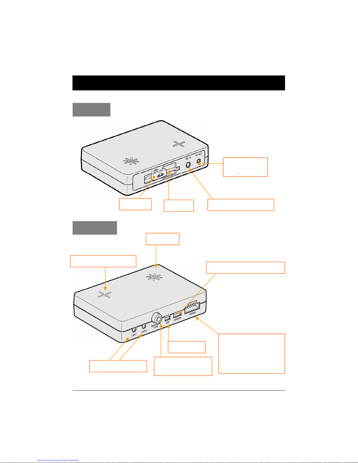
INTRODUCTION
p
p
GPS Input
Alarm (Car Signal)
FRONT
Audio/Video
Out
ut
SD Door
REAR
Internal Microphone
Camera 1, 2 Input
SD Slot
BUZZER
Rear View
Camera Input
External MIC input
Remote Control Input
Power Input &
Input
(Turn left, Turn right,
Brake, Speed pulse)
7
Page 8

INTODUCTION
RED LED
REMOTE CONTROLLER
Record LED
BLUE LED
Overwrite LED
Audio Video Output Cable
SHUTTER BUTTON
PLAY BUTTON
PANIC BUTTON
Audio out 1
[Note] The same screen will be shown through the Video out 1 & 2.
Video out 1 Video out 2
8
Page 9

INTODUCTION
)
()
Power & Car Signal Input
Black (Ground)
Red(+)
FUSE
250V 3A
Yellow (Alarm3)
Blue (Alarm1)
White (Speed pulse)
Green (Alarm2
9
Page 10

FUNCTION (MAIN UNIT)
Turn on the vehicle power, MotionTrak330 will be automatically started
The Event recording will be started automatically by Motion detection
detection or [PANIC] button in the continuous recording file, which can be easily
Automatic start
Make sure that peripherals including cameras are properly connected.
.
(Use the power cable provided.)
Notice : The unit will not start recording immediately after the power is
turned on. It takes around 1 minute for the built-in power backup system
to charge. Thereafter, the internal flash memory will be ready to record.
Event record
,
Alarm1 to 3 or by the G-Sensor level.
The Panic recording can be started by pressing the [PANIC] button.
Normal record (Continuous record)
The Normal (continuous) recording will be automatically started after power on.
MotionTrak330 will not make a separate event file during the continuous
recording. It will mark the Event area as ‘Alarm1 to 3’, G-Sensor, Motion
searched for during playback.
Dual record (Event & Normal record)
If you set different record modes per camera, like camera1 set as Event record
and camera2 set as Normal record, then camera1 (Event record) will work
according to the record setting for example 10 frames per second recording.
However camera2 (Normal record) will record 1 frame per second, if there is no
event. If there is an Event, both cameras will record according to the record
setting for example 10 frames per second recording.
Live screen on Monitor
MotionTrak330 will display the live screen on the monitor.
The camera channel can be changed using the information OSD.
(Refer to page 13)
Playback in the car
Recorded files can be played back in the car.
PC Viewer Software
The software is pre-loaded on the SD card [pcsw] folder.
10
Page 11

FUNCTION (MAIN UNIT)
This also signals any system error
SD Memory Card Format
Remove the power first. Press and hold the [PLAYBACK] & [PANIC] button.
Then connect the power.
Press and hold the [PLAYBACK] & [PANIC] more than 2 seconds after
booting. Then SD card initialization will start.
Once complete, all video & log files will be deleted and the configurations
will default to the factory settings.
Notice : PC Viewer software is pre-loaded on the SD card. Please ensure
you have installed the software to your PC before you format the card.
Built-in power backup (Super Capacitor)
When power to the unit is interrupted, MotionTrak330 creates the last file
using the internal Super Capacitor.
BLUE LED (RECORD)
The Blue LED shows the power is on.
The Blue LED blink during event recording.
RED LED (Overwriting)
The Red LED will be turned on when start overwriting.
Buzzer
“Beep” sound will occur when event/panic recording starts (this can be turned off
in the setting menu on the PC viewer, if required).
.
VIDEO LOSS (warning)
“Beep” sound will occur continuously when video loss.
Check the camera and camera connection then turn off and on the unit to reset it.
And make sure the number of cameras you have connect before turning on the unit.
The number of cameras can be set in the settings menu on the PC viewer.
11
Page 12

OPERATION
System Error Buzzer
1. Make sure that the power cable is properly connected and turn on the car
power.
2. The Blue LED & Red LED will turn on and slowly blinking simultaneously
then the Blue LED will remain on.
The Blue LED light means the MotionTrak330 is now ready for the event
recording and has started Normal recording (Continuous recording).
3. The normal recording (Continuous recording) will be automatically started,
if it set up via your PC.
4. The event recording will automatically begin when triggered by Motion
Detection, Alarm1 to 3 or by the G-Sensor and will begin with one short
“Beep” sound.
5. The panic recording can be started by pressing the [PANIC] button.
Removing the SD memory card
Turn off the power and then check the Blue LED light. Once the Blue LED
light is off, take out the SD memory card.
Inserting the SD memory card
Turn off the power and then check the Blue LED light. Once the Blue LED
light is off, insert the SD memory card.
A “Beep” “Beep” sound will occur and the Blue & Red LED light will blink
simultaneously when there is a system error or the SD card is not inserted.
[Check the SD memory card when this occurs. To solve the problem, initialize
the SD card or if necessary replace the SD card].
12
Page 13

OPERATION
Press [PLAY] button then the INFORMATION OSD (the summery of setting)
FirmwareVersion:2.0.0
INFORMATION OSD
will show up on the monitor as below.
CAM1 CAM2 CAM3
Activated
√√√√
√√
RecordMode
System:NTSC
Quality:Super
Overwrite:ON
Continue Continue Event
Resolution:720X480
FPS:10
Audio:ON
G‐SensorLevel:X:3,Y:3, Z:3
G‐SensorCalibration:
√√
CurrentTime:14:50:0707JUL2011
To change the live display channel, press [PANIC] button.
The INFORMATION OSD will be turned off automatically after 30 seconds.
To turn off the live view, press [PLAY] button or [SHUTTER] button.
LIVE VIEW
Turn on the MotionTrak330 and press [PLAY] button to turn on the
INFORMATION OSD (the summery of setting) . To change the live display
channel, press [PANIC] button to select the camera.
And then press [PLAY] or [SHUTTER] button to escape.
Camera 1 => Camera2 => Camera3 => 3 Cameras together =>
13
Page 14

OPERATION
G
Sensor Calibration is needed after installing the MotionTrak330 to
detect
Pressanysinglebuttontoescape
G-Sensor Calibration
the installed direction of the MotionTrak330 to accurately record the journey
direction.
Press and hold [PANIC] & [SHUTTER] button together and then power on
the G-Sensor Calibration screen will be displayed.
Pressandholdpanicandshutterbutton
simultaneouslymorethan2secondsforcalibration.
.
Parkvehicleonaflatsurfacewith
atleast50meters(164ft)ofspacedirectly
aheadandpresspanicbuttononce.
Movedirectlyforwardandacceleratevehicletillbeep
soundoccur.
G‐SensorCalibrationisfinishedsuccessfully.
Pressanybuttonorwait30secondstoreboot.
G‐SensorCalibrationisfailed.
Parkvehicleonaflatsurfacewith
atleast50meters(164ft)ofspacedirectlyahead
andpresspanicbuttononceagain.
This G-Sensor calibration is only needed the first time the MotionTrak330 is
used.
Retry
14
Page 15

OPERATION
The panic recording by [PANIC] button will start by pressing the [PANIC] button
SNAPSHOT RECORD BY SHUTTER BUTTON
PANIC RECORD BY PANIC BUTTON
with one short “Beep” sound. The Blue LED will blink during the panic
recording.
MotionTrak330 doesn’t make a separate panic file during the continuous
recording.
It will mark the panic area by [PANIC] button in the continuous recording file
which can be easily searched for during playback.
Press [SHUTTER] button the MotionTrak330 will take a snapshot of 1 image
with 5 seconds of audio with one short “Beep” sound.
15
Page 16

OPERATION
Press and hold [PLAY] button for more than 2 seconds
Move to the next file: Press and hold [PANIC] & [PLAY] button
(o)
(o)
(o)
Only Panic data playback
PLAYBACK
The latest recorded file will playback on the screen.
[WARNING] Recording cannot be done during playback.
.
Explanation of PLAYBACK control button
Channel change: Press [PANIC] button.
Move to the previous file: Press and hold [SHUTTER] & [PLAY] button.
.
PLAY/PAUSE: Press [PLAY] button.
SLOW PLAY: Press [PLAY] button more than 1second.
Return to record mode: Press and hold [SHUTTER] button more than 2seconds.
Playback logic at the main unit.
Panic data Event data Normal data Playback
----------------------------------------------------------------
(o) (o) (x) Only Panic data playback
(o) (x) (x) Only Panic data playback
(x) (o) (o) Only Event data playback
(x) (o) (x) Event data playback
(x) (x) (o) Normal data playback
16
Page 17

SOFTWARE USER GUIDE
p
p
pg
MotionT rak330 PC Viewer Guide
[PC SYSTEM REQUIREMENT]
Recommended PC specifications for PC Viewer software
OS Windows 2000, Windows XP
Windows Vista, Windows 7
CPU Pentium4 2.6GHz or higher
RAM 512MB or higher
Interface SD Memory Card Reader
HDD
Free s
Display 1,024 x 768 pixel/High Color(16bit) or higher
If the PC does not meet the minimum system requirement, the PC
Viewer may not function properly.
ace
Install 20MB or higher
Backup 2GB or higher
17
Page 18
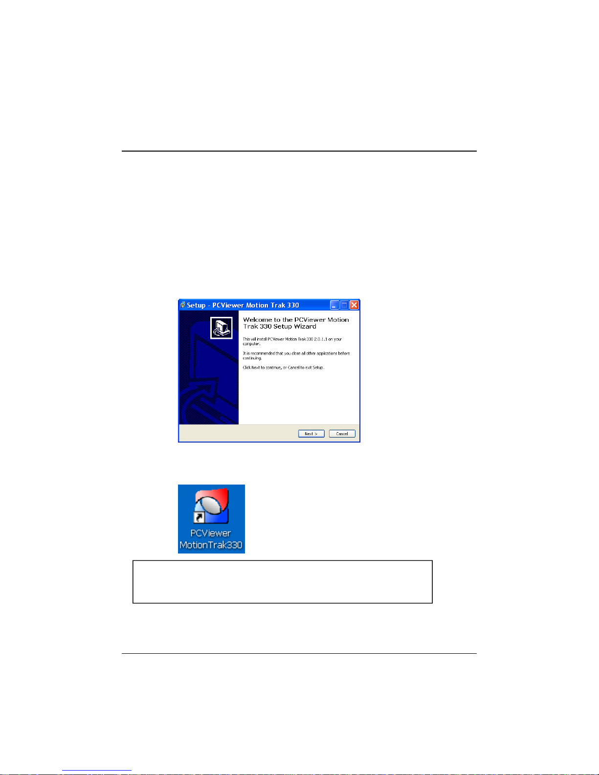
INSTALLING PROCEDURES
1. Connect the SD card into your PC (if your computer does not have SD card
Open the Control Panel
PC Viewer software is in the provided SD card.
slot use the USB SD card reader) and open the “My Computer”.
2. Right-click the “DRIVEREC3” drive and select [Open] .
3. Double click [SETUP.EXE] in the [pcsw] folder.
4. Select the language and then follow the dialog box.
5. The “PCViewer” icon will be displayed on your desktop.
NOTE: To Un-install the “PC Viewer MotionTrak330”
“
Select [remove program] and remove [PC Viewer MotionTrak330].
”
.
18
Page 19

Connect SD memory card
4
Select the SD memory card folder at the folder select window
1. Insert the SD memory card into the SD card reader.
2. Run “PC Viewer MotionTrak330”.
3. Select [File] and then click “Select Data Folder” or Click [OPEN] button.
[OPEN] button
.
.
19
Page 20

PC VIEWER SETTING
To see a better quality of playback pictures on your PC, check [Deblocking] box.
To set PC Viewer select [File] and then click” PC Viewer Setting”.
This setting is for the PC Viewer software itself.
To set the recorder, refer to page 27.
The ‘date’ formats and ‘speed’ of the unit will be set automatically according to
the PC Windows setting.
However it can be changed with this PC viewer setting menu.
20
Page 21
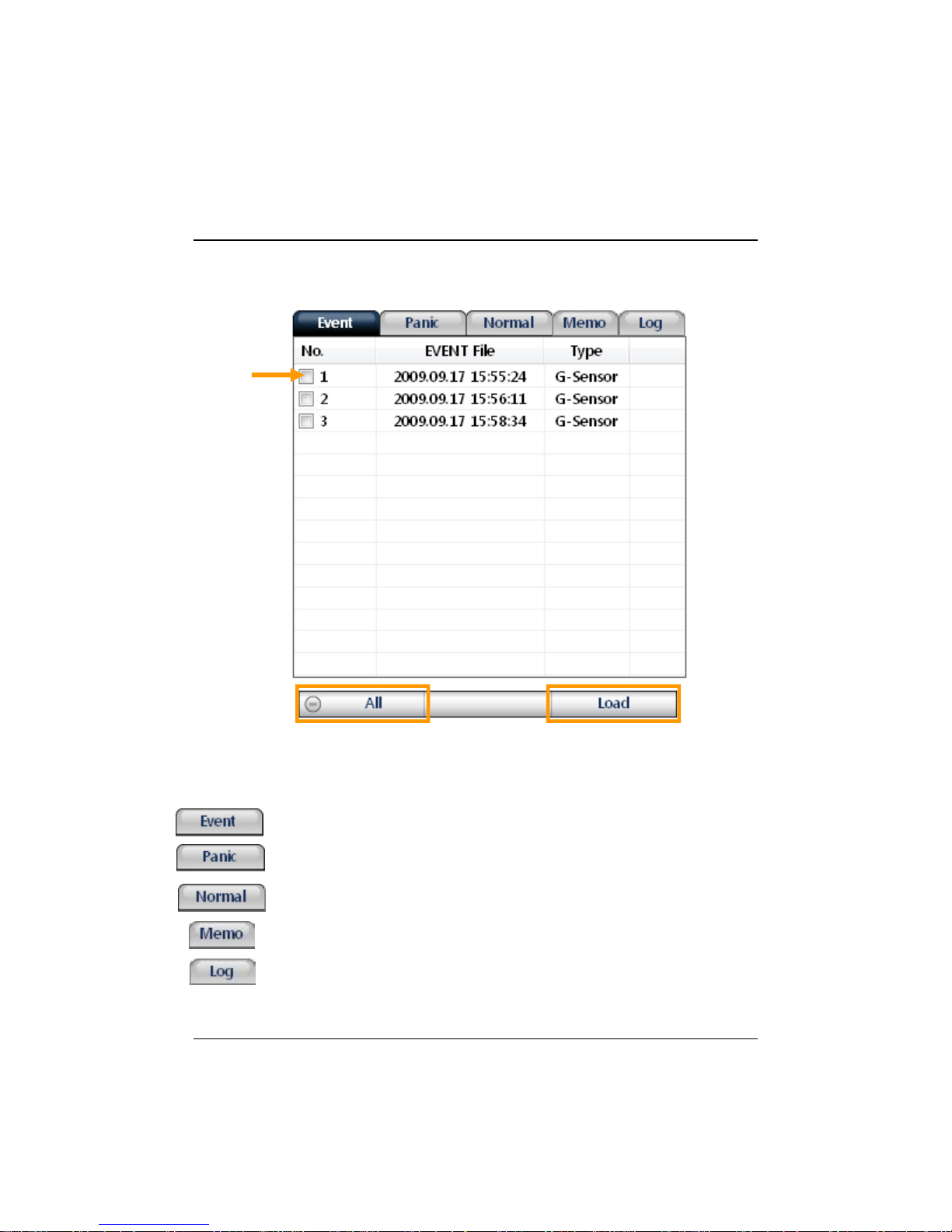
FILE LOADING
Check the file from the list using mouse or click [All] button.
And then click [Load] button.
Check
the file
[All] Button
All recordings and snapshot files will appear the file area under the tab:
The Event file list recorded by G-Sensor Motion detection, or Alarm1 to 3.
The Panic file list recorded by pressing the [PANIC] button.
The Continuous record file list.
The Snapshot file saved by pressing the [SHUTTER] button.
The Log file list.
[Load] Button
21
Page 22
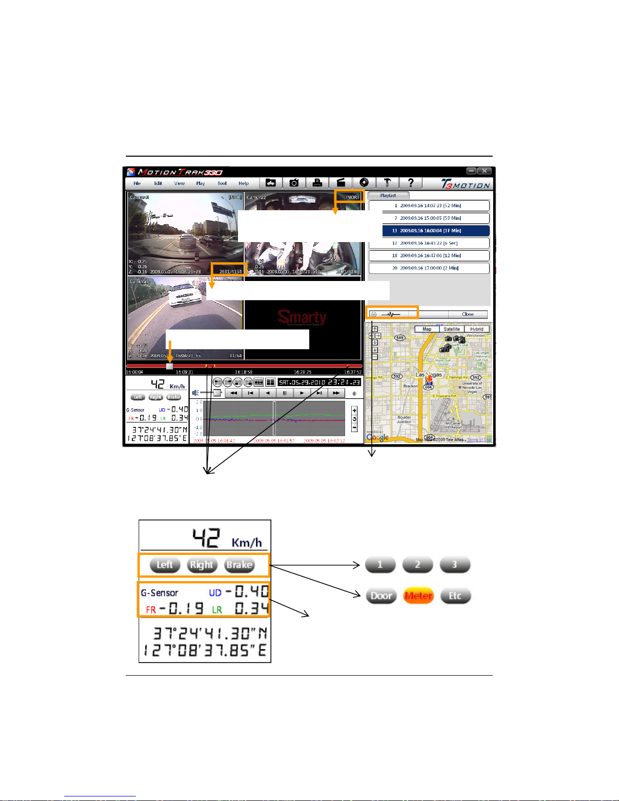
PLAYBACK SCREEN
[NOR]: Normal Recording
[G-Sensor]: Event Recording
Display frame/Total frames number
Playback position indicator
Event data search button is
The Yellow mark indicates there is an
Event triggered by the G-Sensor, Alarm1 to 3
or the [PANIC] button.
The ‘icon name’ can be changed in the
setting menu.
GPS location information(the north latitude, the east longitude)
enabled when playing back Normal
recorded files.
Eg:
G-Sensor Data
UD: Up/Down direction
FR: Front/Rear direction
LR: Left/Right direction
22
Page 23

PLAYBACK
X
X
6. Click [PLAY] button for playback.
CH1 CH2 CH3
Volume
Drag & Move the white line to move the
playback position.
Playback buttons
X2, 4, 8, 16
Fast Reverse
Previous
X0.5, 1
Reverse
Play
Pause Next
Image
0.5, 1
Playback speed
Date & Time
2, 4, 8, 16
Fast Forward
Image
Single View (CH1, CH2, CH3) Quad View
4x4 Multi View (Thumb-nail function)
Zoom In G-Sensor graph
Reset Zoom
Zoom Out G-Sensor graph
23
Page 24

PLAYBACK
Playback speed
control
Ctrl
+ F
NOTE: PC Keyboard hot buttons
Function PC keyboard hot buttons
1024x768 mode Enter
Return to the previous mode: Enter
Full screen mode Alt + Enter
Return to the previous mode: Enter
0.5 => 1
Reverse playback speed control Ctrl + B
0.5 => 1
Pause / Play Space
Previous Image → direction button.
Next Image ← direction button
24
Page 25
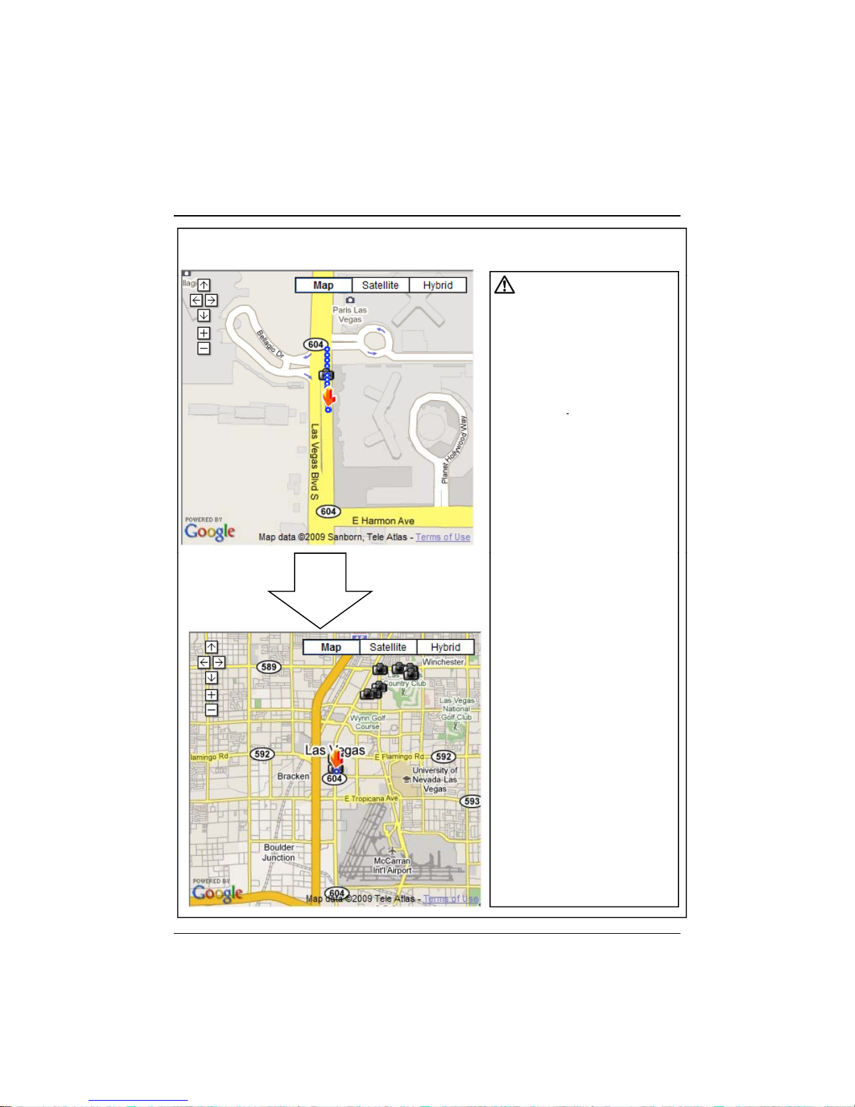
Google map (Event Recording File)
a recorded file.
The route taken will be displayed on the Google map at lower right
corner of the software.
To see the route
& position on the
Google map, the GPS
data should be
recorded with video.
To see the map,
the PC should be
connected to
the Internet.
The playback position
will be shown on the
map with an arrow.
The blue markings show
the route taken.
Double click the blue
mark to change the
Zoom Out
video playback position
to that point.
The camera icon
indicates that there is
The total camera icons
shown will be less
than 100, even if
there are
more than 100 events.
When the unit is set to
Normal recording mode,
there is no
route & camera icon
on the map.
25
Page 26
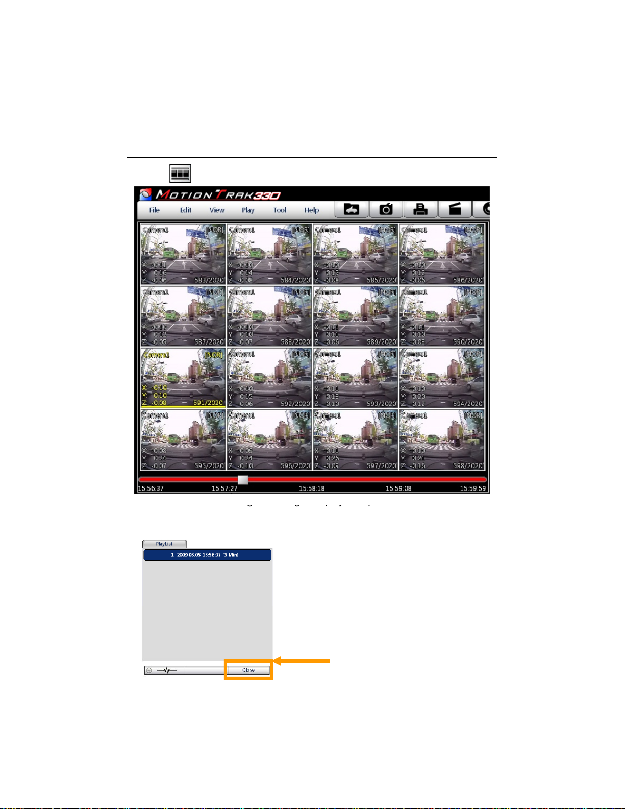
Thumb-nail Function
ggpyp
Click [Cl
7. Click button for 4x4 multi view (Thumb-nail function)
Click the thumb-nail image to change the playback position.
Click right button of mouse to go back to Single/Quad image playback mode.
8. Click [Close] button to quit the event playback.
ose] to finish
the event playback.
Then the [PlayList]
window will be changed
to the initial status.
26
Page 27
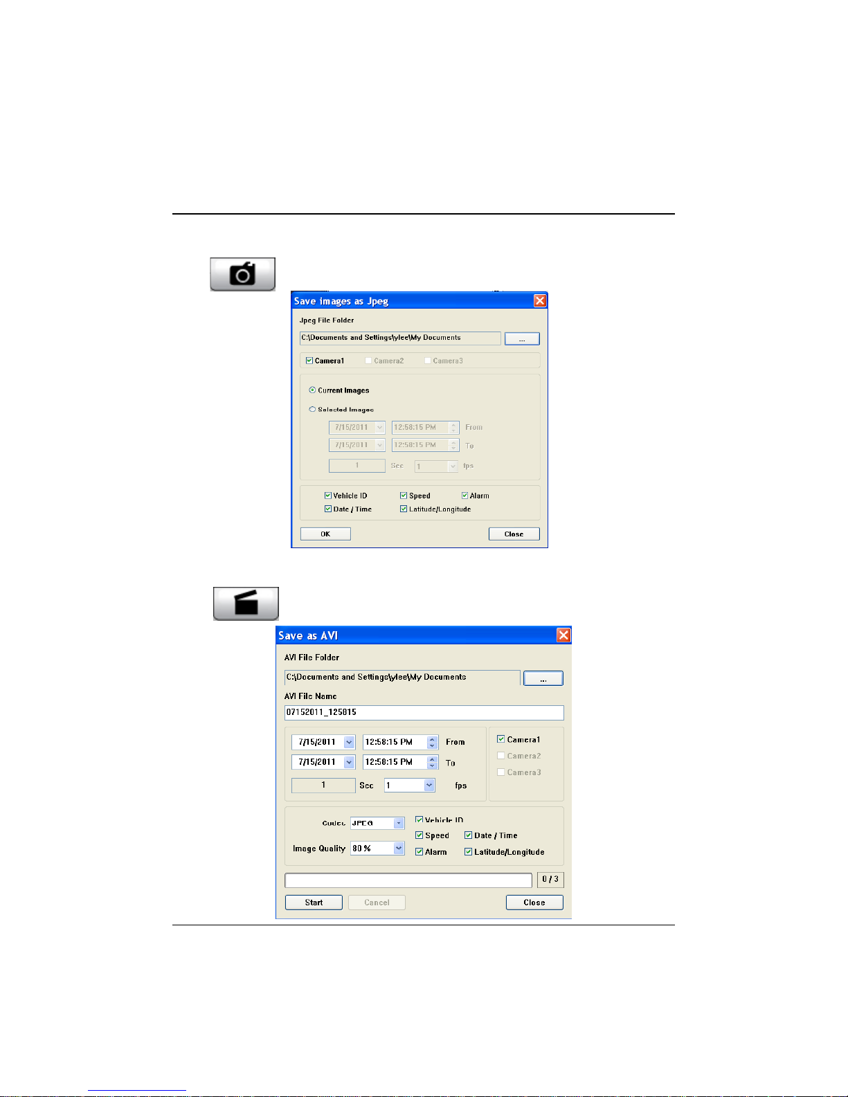
Save JPG file & AVI file
‘S
Pause the playback and click ‘Save Image’ icon to make a JPG file.
ave Image’ icon
Pause the playback and click ‘Save AVI’ icon to make a AVI file.
‘Save AVI’ icon
27
Page 28
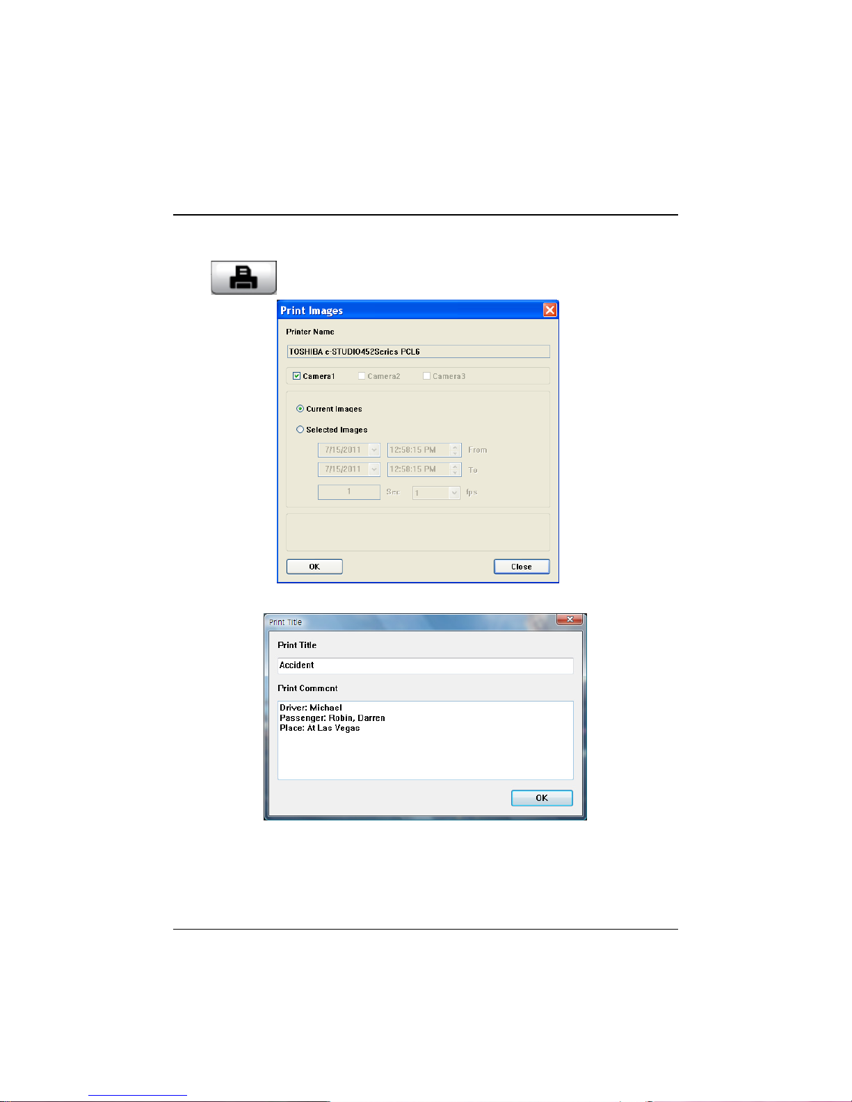
Print image
11. Pause the playback and click ‘Print Image’ icon.
Print image icon
Input [Print Title] & [Print Comment] using Keyboard.
Total Print Comment window allows up to 7 lines total.
28
Page 29
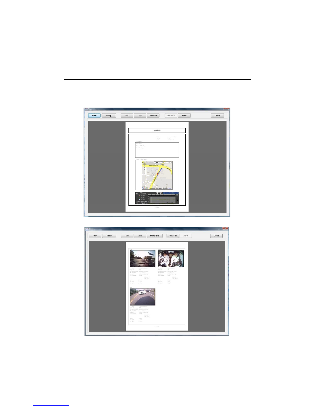
Make Report
first page
12. Click [Print] button in the print preview windows for printing.
[Print Title] & [Print Comment] & G-Sensor graph & map will be printed on the
.
Click [ 2x2 ] and then click [Print] to print 4 images in one page.
To print CH1~3 together select 1frame only.
29
Page 30

Backup
Check [Backup All] and press [Start] button to backup all files
13. Click [Backup] icon to backup the files to the PC.
[Backup] icon
Check & Load [Event], [Normal], [Panic] [Log] & [Memo] data first, before
clicking the [Backup] icon.
The selected files will appear in the lists in the Backup windows.
OR
.
30
Page 31
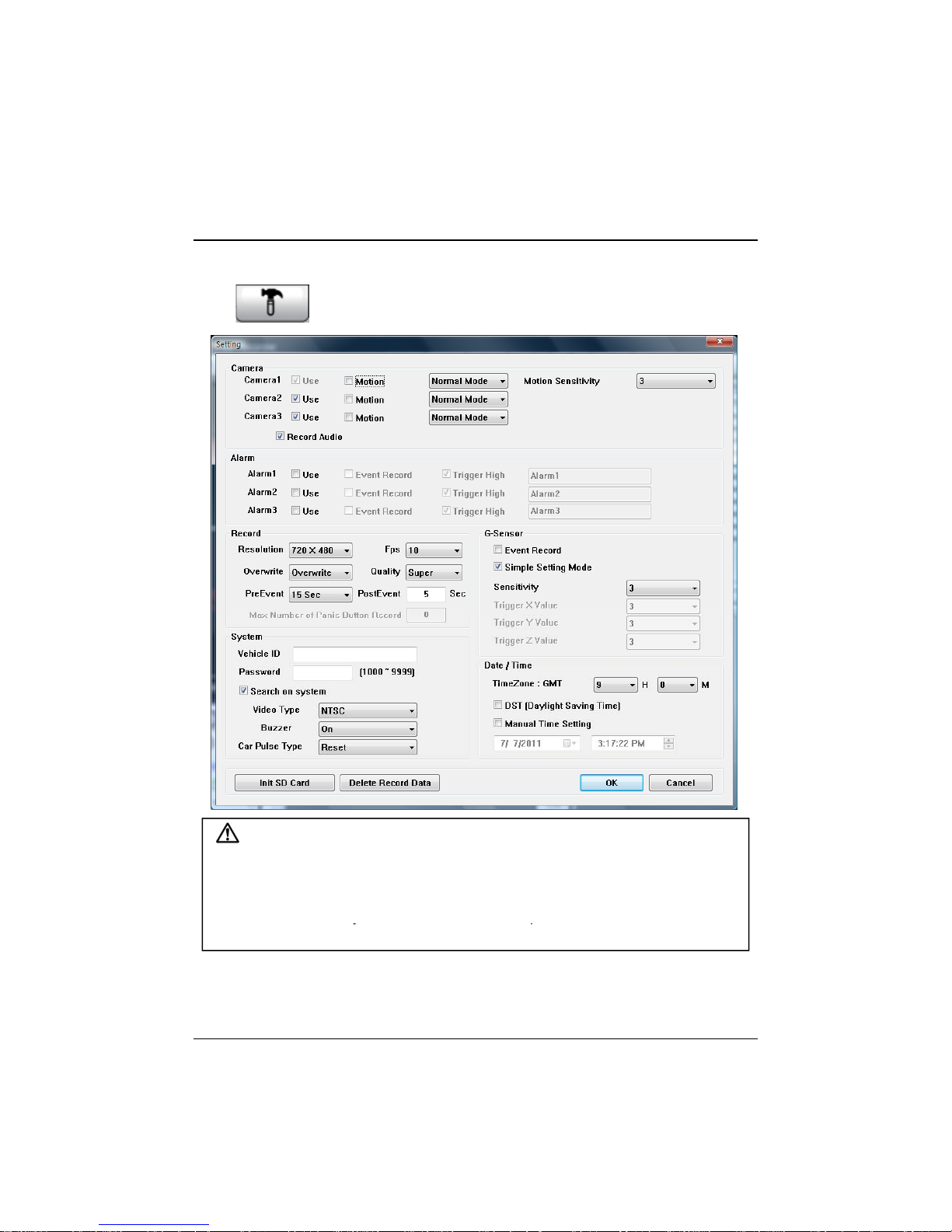
Setting Drive Recorder
[Setting Drive Recorder] icon
y
yp
14. Click [Setting Drive Recorder] icon for setup.
Caution
Backup SD card data first, before clicking initialize SD card button or
before changing the Record Mode from Normal Mode to Event Mode or
vice versa. All normal recording data or all event recording data in SD card
will be automaticall
Once done, the old data cannot be recovered.
Initialize SD card : All data will be deleted and the configuration of Drive
Recorder will default to the original factory settings.
Record Mode Change: All normal recording data or all event recording data in
SD card will be automatically deleted to free up space on the SD card.
deleted to make a free space on the SD card.
31
Page 32
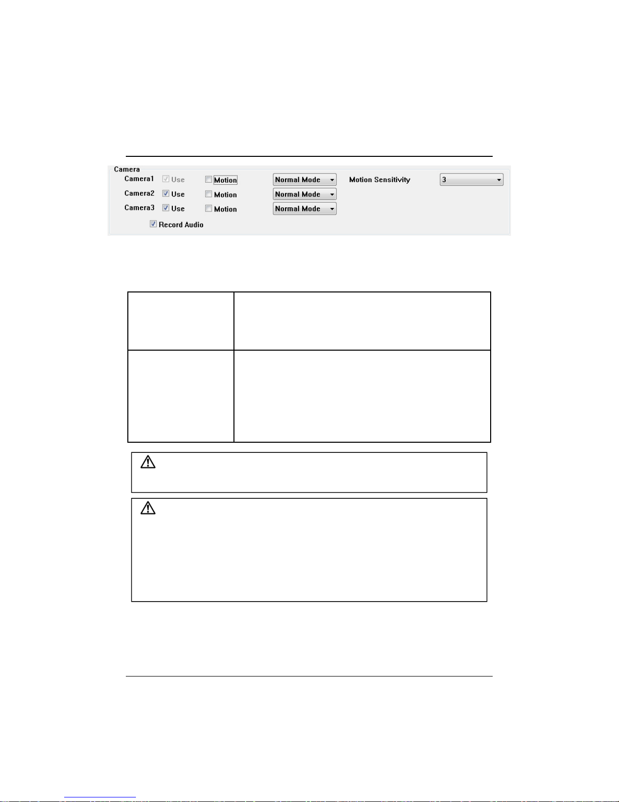
Setting Drive Recorder
Record Mode
Normal Mode: Continuous recording will automatically
3 (Middle): Default
To record Camera2 or Camera3, check “Use” box.
To record Audio, check “Record Audio” box.
To use Motion Detection as an Event, check “Motion” box per camera.
start after booting the MotionTrak330.
Event Mode: Recording by Motion Detection,
G-Sensor, Alarm1 to 3 or [PANIC] button.
Motion Sensitivity Select Motion Detection Sensitivity from 1 to 5.
5 (High): The most sensitive
4
value
2
1 (Low): Insensitive
To record by Motion Detection
Check Motion per camera and set Record Mode as Event Mode.
Dual Recording (If you set different record modes per camera)
Camera1 can be set to Event record and camera 2 set to Normal record,
then camera1 (Event record) will work according to the record setting for
example 10 frames per second recording, when there is a event. However
camera2 (Normal record) will record 1 frame per second, if there is no
event. If there is an Event, both cameras will record according to the record
setting for example 10 frames per second recording.
32
Page 33

Setting Drive Recorder
L
fil
lity)
bel
20f
720x480
Resolution 720x480, 720x240
Frame Rate 1 Camera supports 1~30 fps
2 Cameras supports 1~15 fps @ 720x480
2 Cameras supports 1~30 fps @ 720x240
3 Cameras supports 1~10 fps @ 720x480
2 Cameras supports 1~15 fps @ 720x240
Quality(4 level) Super (Large file size, but good picture quality)
ow (Small
e size, but low picture qua
Pre Event
Post Event
Overwrite Overwrite (The image data overwrites the oldest
If you set Event mode only, the Max Number of Panic button Record will be
5~500.
If you set different record modes per camera (Normal Mode and Event
Mode), the Max Number of Panic button Record will be 5~10.
Pre-record/Post-record time can be set here.
Pre-record time is 5~30secs, if total frame rate is
below 10fps @ 720x480.
Pre-record time is 5~15secs, if total frame rate is
30fps @ 720x480.
Post-record time is 5~300secs, if total frame rate is
ow
ps @
Post-record time is 5~15secs, if total frame rate is
30fps @ 720x480.
files when the SD memory is full.)
One time (The recording stops automatically when
the SD memory is full.)
.
33
Page 34
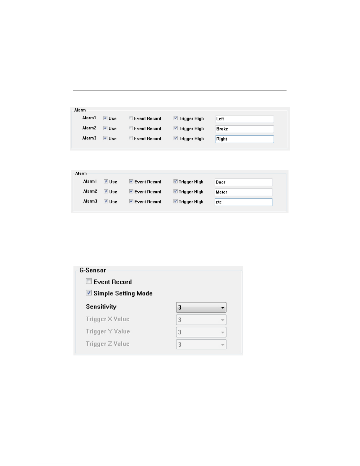
Setting Drive Recorder
G
Sensor sensitivity value is too high like 5, it becomes too sensitive, so it will
To record the car signal with video, set the Alarm configuration as below.
To use the Alarm as an Event trigger, (i.e: so Event recording will start when a
door is open or Meter is on) set the Alarm configuration as below.
G-Sensor setting
-If
detect even a light impact or light turn.
If G-Sensor sensitivity value is too low, so it might not detect a notable incident.
So, sensitivity should be set in consideration of a vehicle’s suspension, condition
and also the road condition.
If you don’t want to record an Event triggered by G-Sensor, un-check Event
Record box.
34
Page 35
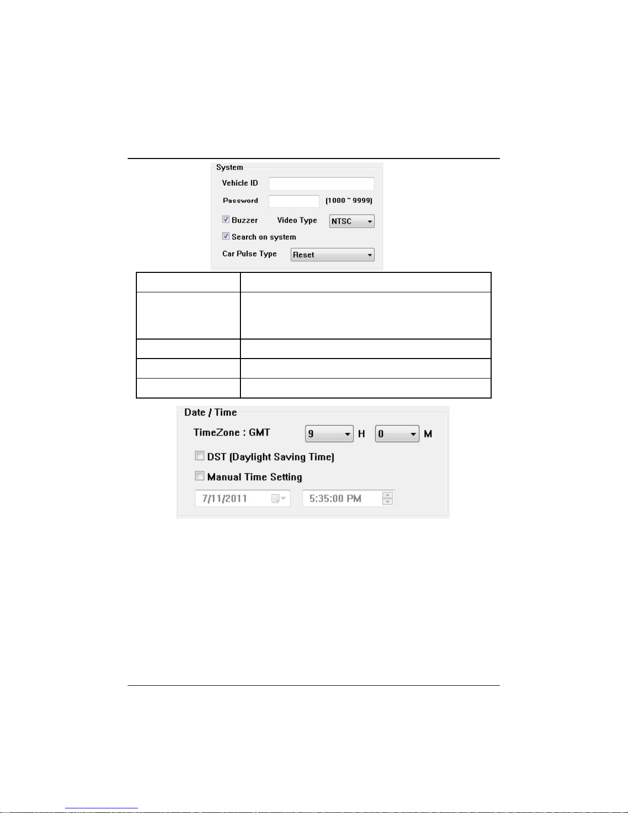
Setting Drive Recorder
Password
Enter 4 numbers from 1000 to 9999 as a password
Vehicle ID Type in your Vehicle ID
[Search on system] function (Playback on a car) will
not work after selecting a password.
Buzzer “Beep” sound ON/OFF when Event recording starts.
Video Type This should be set by Camera Video type.
Search on system To use the playback function on the recorder.
.
To record the exact time, the time zone setting is important.
Once you set the time zone, automatically synchronize time using GPS
time. However Manual time setting is also available.
35
Page 36
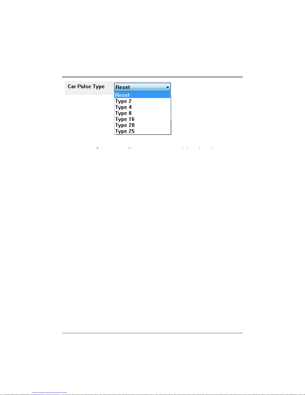
Setting Drive Recorder
gyp, (pp)
Before using “Car Pulse Type”, connect the White (Speed pulse) cable to
the speed pulse line on your car. Please consult your car manufacturer or
a car repair shop regarding this connection.
To receive the speed from the car using the White (Speed pulse) line,
select the speed pulse type of your car.
If you don’t know the speed pulse type of your car, select “Reset” and
drive for more than 30 minutes.
The MotionTrak330 will compare the speed pulse and GPS speed and
automatically set your car pulse type.
36
Page 37

Setting Drive Recorder
NEW SD Memory card initializing should be done using Tool menu
We recommend that SD initialize be
Initialize SD card : All date will be deleted and the configuration of Drive
Recorder will default to the original factory settings.
Delete Record Data : All data will be deleted.
Caution
Once the record setting was changed, all recorded
data in SD card will be removed automatically.
Select Backup [YES] or [NO] before lost the all
recorded data.
STEP 1. Insert new SD memory card into
the PC.
STEP 2. Run “PC Viewer MotionTrak330”.
STEP 3. Select [Tool] and then click
[SD Initialize].
performed at least once per month to
prevent the MotionTrak330 from
encountering software errors.
.
37
Page 38
Setting Drive Recorder
A
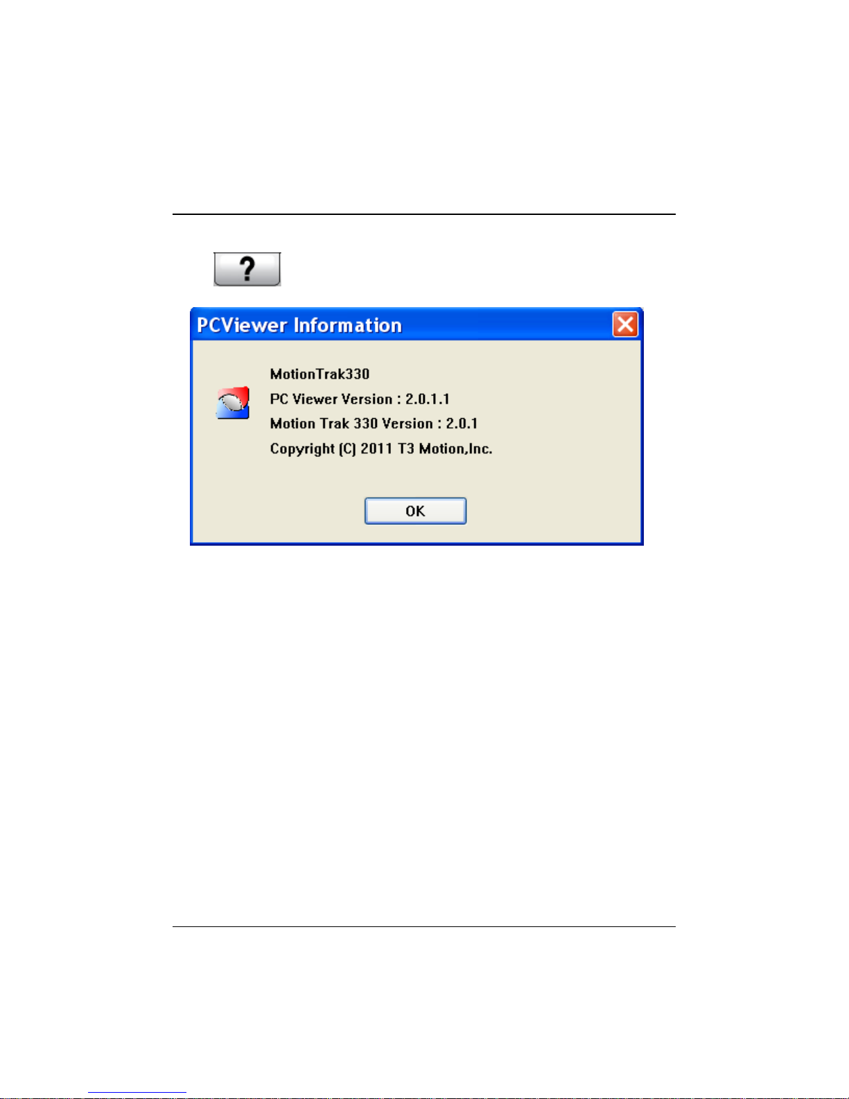
15. Click [About] icon to check the product information.
bout icon
38
Page 39
LOG FILE PLAYBACK
search is entered. If any recorded video data matches the search query, a
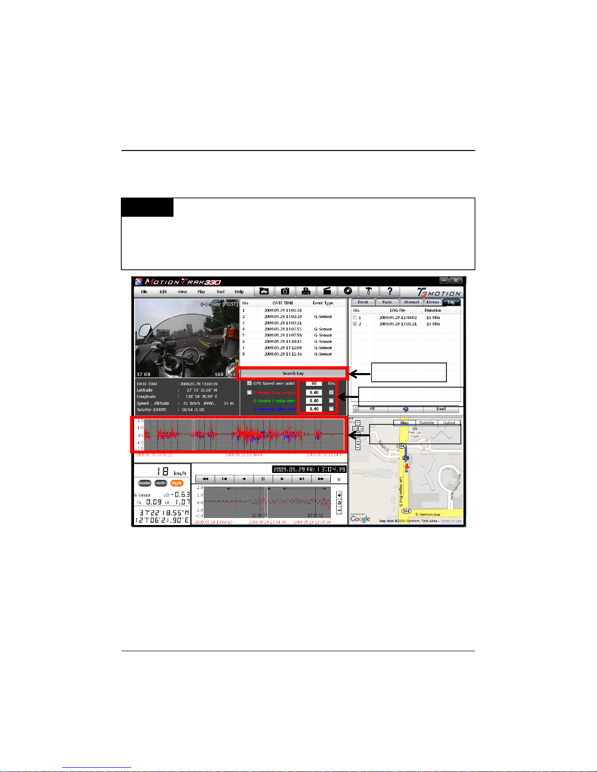
16. Select [LOG] tab windows and then check the log from the log list using
mouse or click [Check All] button. Then click [Load] button.
Log data
events. The total log data size can not exceed 48MB. The unit overwrites the
oldest data when 48MB is reached. Log data can be used via the data sorting
function to help find specific data (for example, to find all the times when the
vehicle was travelling at more than 80mph (or 129km).
Log data will be recorded during driving even if there are no
Search button
Input sorting data
G-Sensor graph
GPS speed, G-Sensor X value, G-Sensor Y value, G-Sensor Z value data
can be used to narrow a search for journey information. The small check
box at right side of each value should be checked before the data for the
list will show up with [Switch] or [G-Sensor] indicators to show how the
recording was triggered.
G-Sensor X value: Front/Back movement (like a harsh brake or quick start).
G-Sensor Y value: Left/Right movement (like a harsh turn).
G-Sensor Z value: Up/Down movement (like a bump or depression).
39
Page 40
GPS LOG TO KML CONVERTER (for Google Earth)
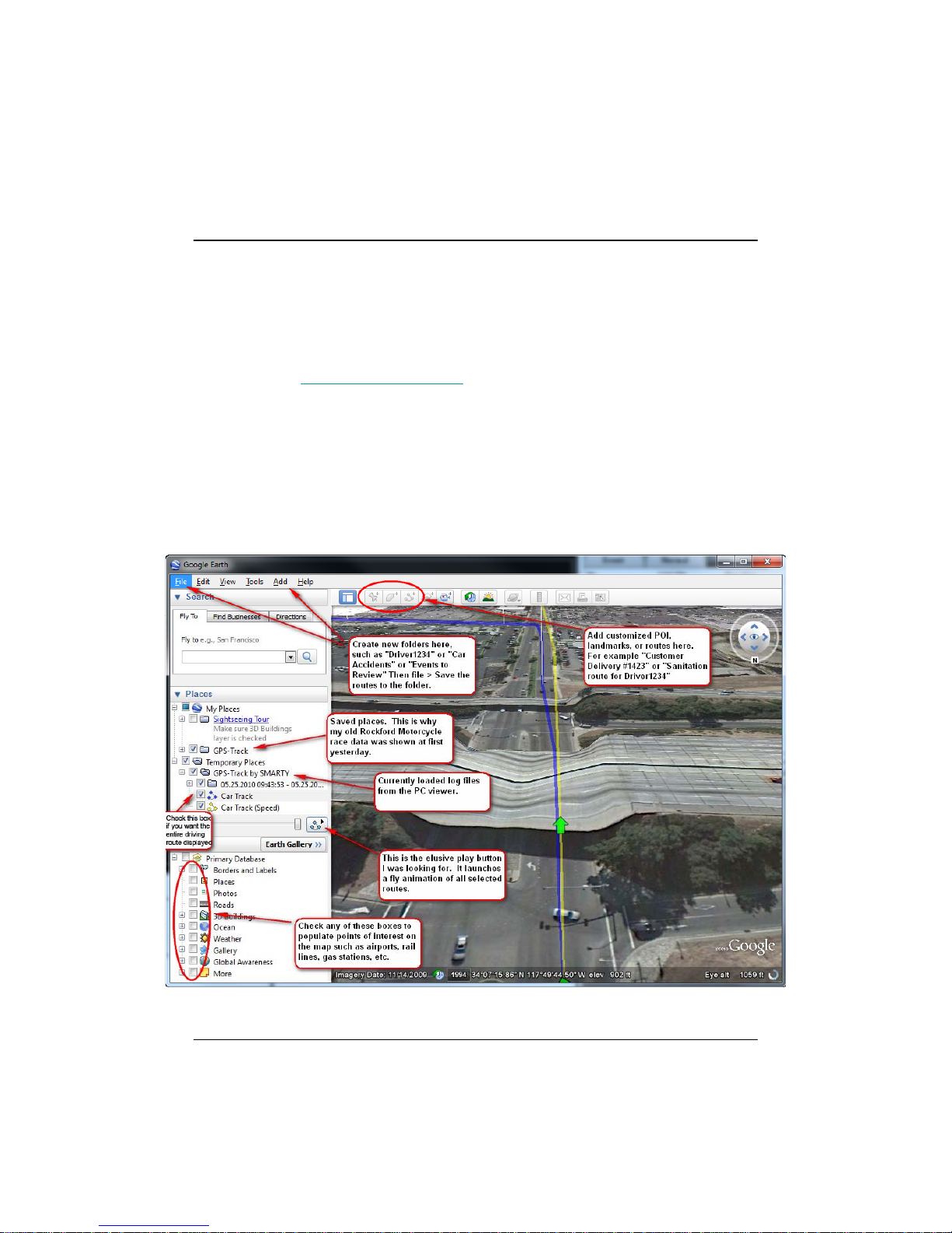
To see the whole route on Google Earth, select a log file and click Google
Google Earth icon
Earth button.
STEP 1. Install Google Earth on your PC. It is free of charge.
(http://earth.google.com/
STEP 2. Check the log file.
STEP 3. Click Google Earth button.
Then the route will be exported to Google Earth, which will
automatically launch.
)
40
Page 41

GPS LOG TO KML CONVERTER (for Google Earth)
Google Earth lets you import the log data, save routes, add place marks
(i.e. customer pick up locations, or other points of interest),
add driving routes to compare with the actual route taken, and lets you
save it all within Google Earth for easy and free data management!
You can view and download Google Earth tutorials and user guides here:
http://earth.google.com/support/bin/static.py?page=guide_toc.cs
41
Page 42

Recording / Storage Time Table (NTSC)
Note: This is a guideline only. Actual results may vary depending on a variety of
factors (Video signal, image, etc.).
42
Page 43
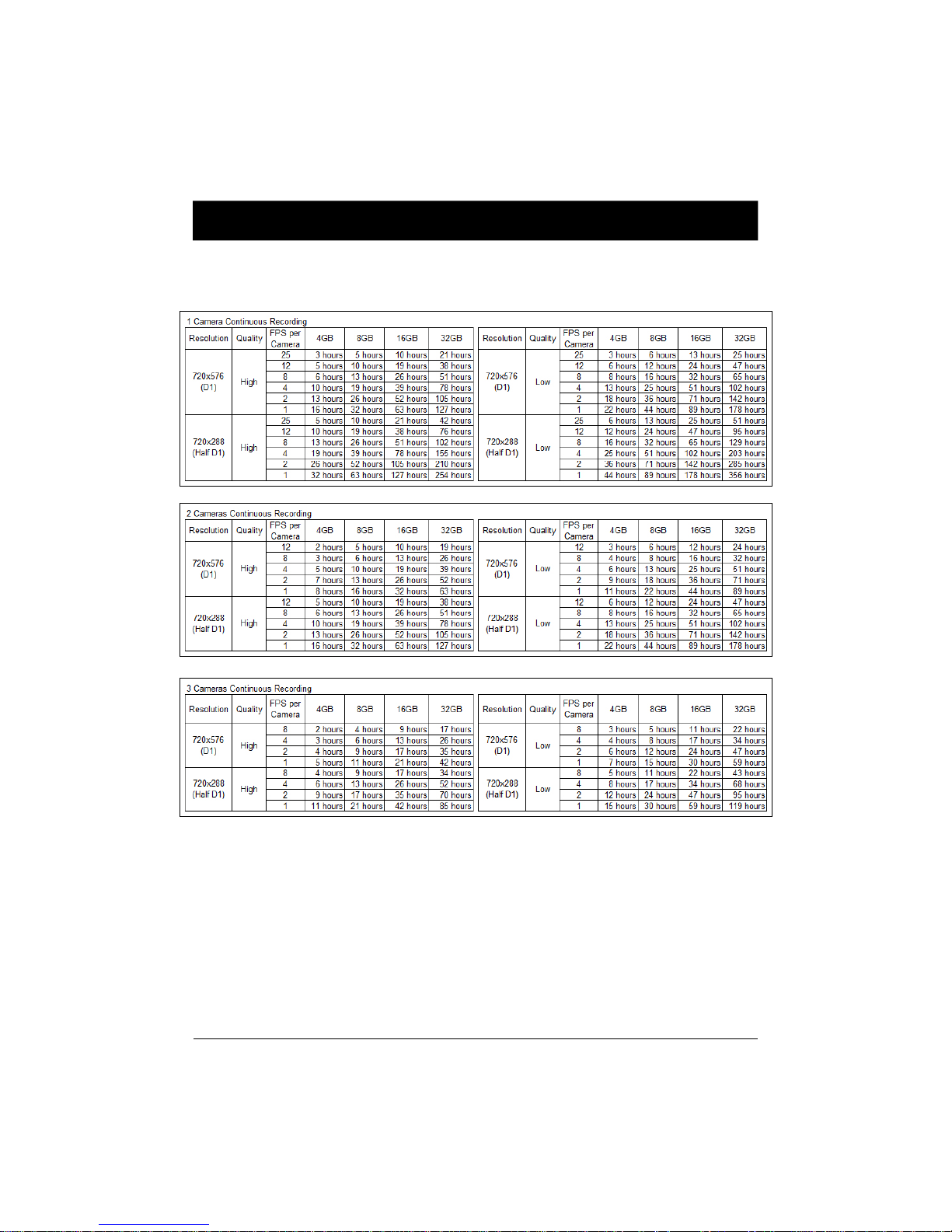
Recording / Storage Time Table (PAL)
Note: This is a guideline only. Actual results may vary depending on a variety of
factors (Video signal, image, etc.).
43
Page 44
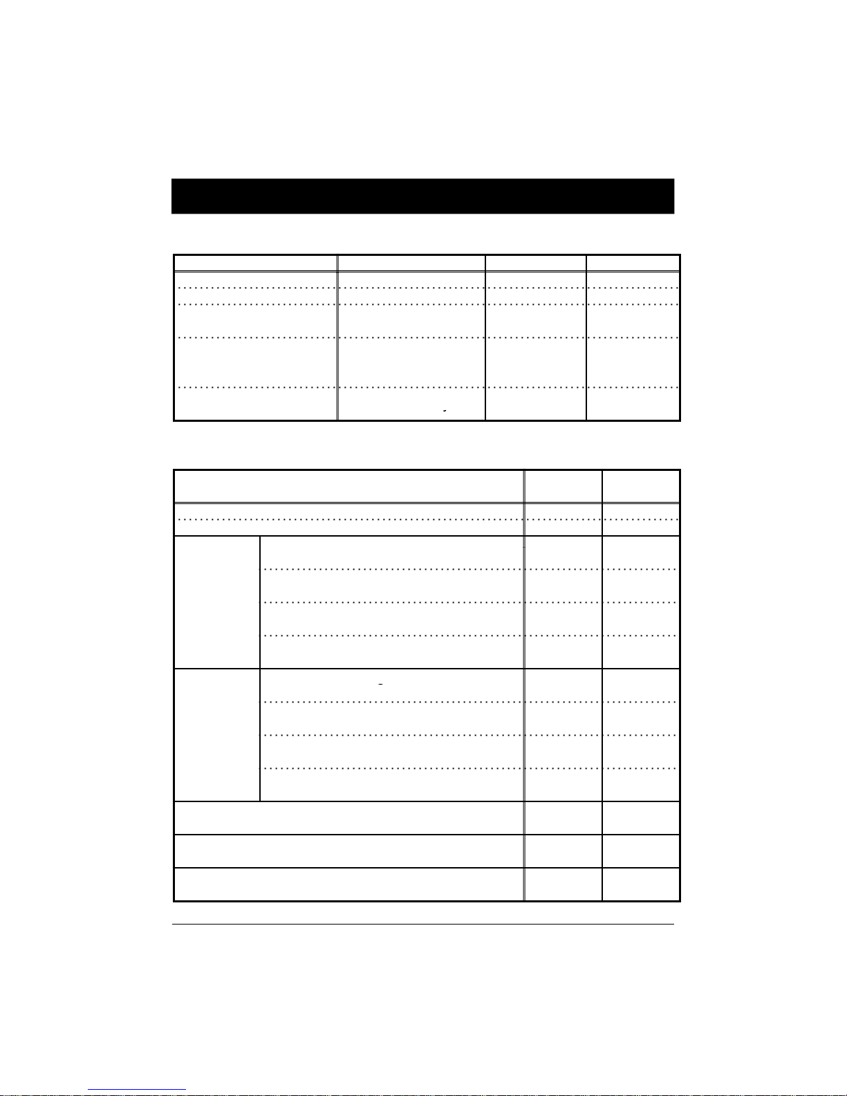
Buzzer / LED specification
y
record mode
y
Pre Event recording
g
g
ON
ON
One Time record
mode
(When
SD card full
)
OFF
S
* Buzzer specification
Condition Buzzer No. Buzzer On Buzzer Off
Event 1 1 sec SHUTTER(Snap shot) 1 200 msecs Press button and then
changed mode
SD card fail
SD card full at [One time]
* LED specification
Stop by pressing
[PANIC] button
1 200 msecs -
continuously
continuousl
500 msecs 500 msecs
2 secs 2 secs
Before
Overwriting
During
Overwriting
Status
Power on ON ON
Booting ON/OFF ON/OFF
Continuous recording
Event recording
Event recording during continuous
recording mode. (5 seconds)
SHUTTER recording
Pre Event recordin
Continuous recording
Event recording
Event recording during continuous
recording mode. (5 seconds)
SHUTTER recording
During Playback
OSD menu
SD Card fail
Blue
LED
ON OFF
ON/OFF
Quickly
ON/OFF
Quickly
ON/OFF
Quickly
ON/OFF
Quickly
ON/OFF
Quickly
ON/OFF
Quickly
ON/OFF ON/OFF
ON/OFF
Slowly
Red
LED
OFF
OFF
OFF
ON
ON
ON
ON/OFF
lowly
ON/OFF
Slowly
44
Page 45
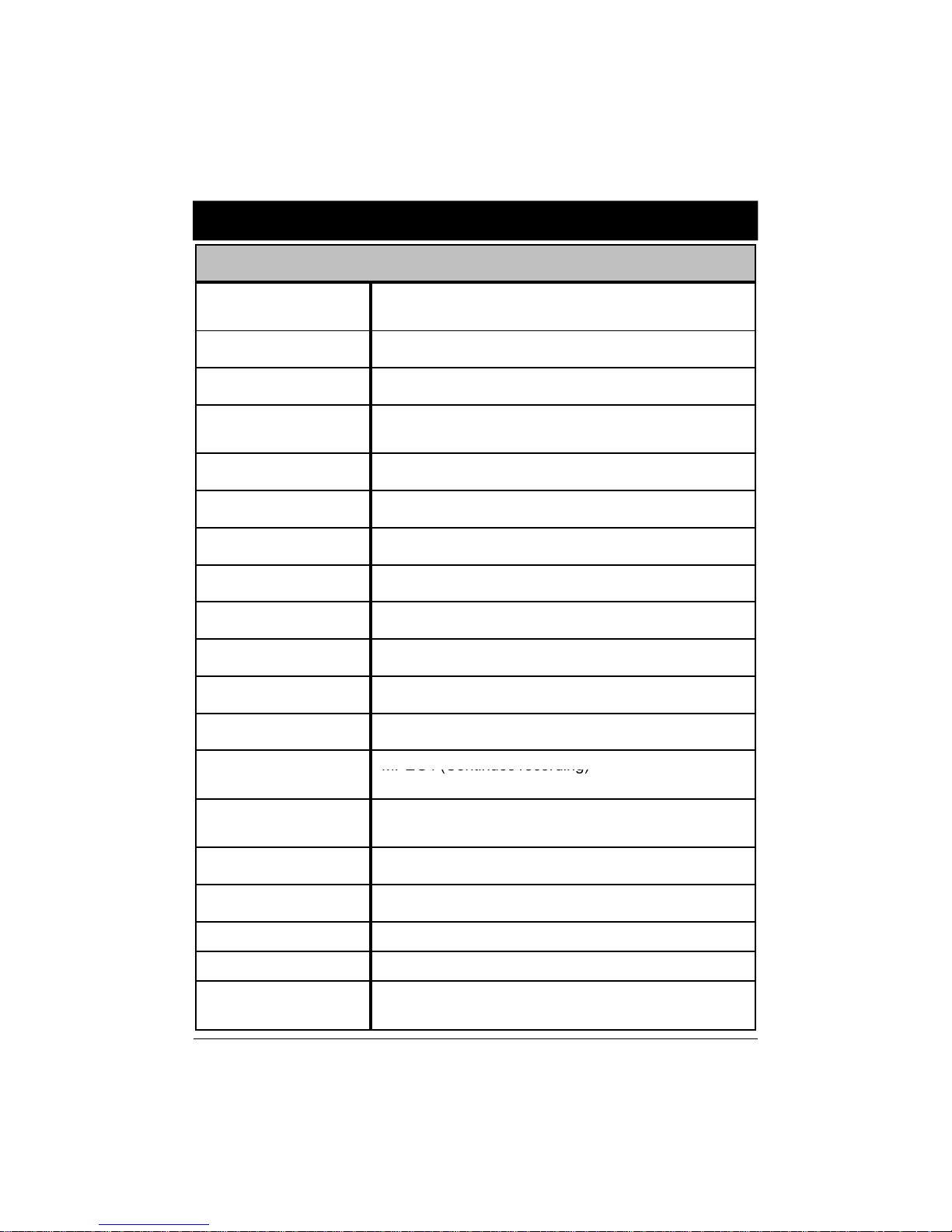
SPECIFICATION
Video In
G-S
Int
C
MPEG4 (Continues recording)
Model: MotionT rak330
CH1- 5V camera in, CH2- 5V camera in,
CH3- camera in
Audio In 1CH (Internal / External Microphone)
AV Out 1 Video out, 1 Audio out
Continuous record
Event record
Recording time 2hours ~ 356hours (14days 20hours)
Shutter record Still Image + Audio (5 secs)
Main memory 4GB SDHC (support 32GB SDHC)
GPS External GPS Module
ensor
RTC Internal battery
Car Signal Brake, Left Turn, Right Turn, Speed Pulse
Alarm Input 3 (Door, Meter, etc.)
ompression
Remote controller
LED 2 (Red/Blue)
NTSC: 720x480 (30fps) 720x240 (60fps)
PAL: 720x576 (25fps) 720x288 (50fps)
ernal 3-axis G-Sensor
MJPEG (Event recording)
PANIC button, PLAYBACK button,
SHUTTER button
Analysis Software PC Viewer (support Google Earth)
Super Capacitor Enable recording last file and shut down
Power consumption 7.8W (when recording 3cameras)
Size/Weight
70mm X 99 mm X 21mm, 100g,
2.76in X 3.9in X 0.83in, 0.2lbs
45
Page 46

Technical Support & Warranty
pp
pp , p y
TECHNICAL SUPPORT
For Technical Su
LIMITED WARRANTY
This product is supplied with 1 year warranty. The warranty excludes products
that have been misused, (including accidental damage) and damage caused by
normal wear and tear. In the unlikely event that you encounter a problem with
this product, it should be returned to the place of purchase.
ort, please contact your local distributor.
46
Page 47

A
Optional Item
Effective Pixel: 648 (H)
488 (V) (NTSC/PAL)
A
Video out: 1.0
Vp
p (Composite)
A
A
I
12V (
±
20%)
Dimension
0mm
DTR-100
STR-100
IR Camera
STR-100IR
Rear View Camera
STR-131
MIC-100
SH-100
DC 5V, CMOS camera for MotionTrak330
1/4" CMOS Digital Sensor 310K pixels
ngle of View: 170°[horizontal(131°) vertical (96 °)]
Video out: 1.0 Vp-p (Composite)
Min. Illumination: 1 lux
Operating Temperature: -20°C ~ 60°C (-4°F ~ 140°F)
Input Voltage: 5V, Power consumption: 0.5W
30mm x 35mm x25mm, 50g, Wire : L=5000±10mm
DC 5V, CCD camera for MotionTrak330
1/3" Sony Super HAD CCD
ngle of View: 90
Effective Pixel: 510(H) X 492(V) (NTSC), 500(H) X 582(V) (PAL)
Min. Illumination: 0.1 lux
Operating Temperature: -20°C ~ 60°C (-4°F ~ 140°F)
Input Voltage: 5V, Power consumption: Max 200mA
43mm x 38mm x 35mm, 70g, Wire : L=5000±10mm
DC 5V, CCD camera for MotionTrak330
1/3" Sony Super HAD CCD
ngle of View: 145
Effective Pixel: 510(H) X 492(V) (NTSC), 500(H) X 582(V) (PAL)
Video out: 1.0 Vp-p (Composite)
Min. Illumination: IR LED On 0 lux
Operating Temperature: -20°C ~ 60°C (-4°F ~ 140°F)
Input Voltage: 5V, Power consumption: Max. 320mA(LED ON)
43mm x 38mm x 35mm, 70g, Wire : L=5000±10mm
CMOS Rear View Camera, Waterproof (IP 68)
1/4" Hi Resolution CMOS
ngle of View: 162
Effective Pixel: (H)640ⅹ(V)480 (NTSC / PAL)
Video out: 1.0 Vp-p (Composite)
Min. Illumination: 1 lux
Operating Temperature: -30°C ~ 85°C (-22°F ~ 185°F)
nput Voltage: DC
Low Power consumption: Max. 35mA
28.00 x 29.00 x 26.00 mm, 113g, Include 8m extension cable
External Microphone for MotionTrak330
Directivity : Uni-directional
Sensitivity : -36±5dB(finished product) At 3V, 2.2Kohm, 0dB=1V/Pa 1KHz
Impedance : 2.2K Ohm@1KHz
Max. Operating voltage : 10V Stand Operating voltage : 3V
Frequency : 100~10,000Hz Current Consumption : 0.5mA Max.
Operating Temperature: -40°C ~ 85°C (-40°F ~ 185°F)
: Φ9.7 x 5.
Plug: Φ3.5mm, mono straight shape, Wire : L=2600±10mm
Steel Housing for MotionTrak330
Dimension : 155.00 x 130.00 x 24.00 mm, 330g
6.1 x 5.12 x 0.94in, 0.73lbs
x
Ⅱ
°
-
Ⅱ
°
°
47
Page 48

Optional Item (Safe Power Cable)
droppedbelow12Vor24V.
Connect(+)tothefusebox
Modelname:DPWR‐300
Thesafepowersupplycablewillallowyoutohardwirethe
DriveRecorderseriestothefuseboxofyourvehicle.
Fuse:250V1A
Thesafepowersupplycablewillautomaticallycut
offthebatterypowerwhenbatteryvoltage
Itshouldbeconnectedtoabatterycircuit.
Thegroundcableshouldbeconnectedtocarchassis.
.
48
Page 49

MEMO
Page 50

MEMO
Page 51

Page 52
2990 Airway Avenue
y
Building A
Costa Mesa, CA 92626
(714) 619-3600 phone
(714) 619-3616 fax
http://www.t3motion.com http://www.motiontrak.com
C 2010 T3 Motion, Inc.
 Loading...