

T2 MD-EM1 Owner's Manual
ENCLOSURE MOUNT MODULATOR
OWNER’S MANUAL
V
I
D
E
O
P
R
E
S
E
N
T
TV
VIDEO
MODULATION LEVEL
STD
CHANNEL SELECT
HRC
IRC
OFFSET MODE
25dBmV
UP
35dBmV
OUTPUT LEVEL
DOW
N
MD-EM1

System Set-up::
OUT
S-VIDEOS-VIDEO RF-OUTRF-OUT
VIDEO PRESENTVIDEO PRESENT
NONO NCNC CC
VV RRLL7575OO 1K1KOO
Introduction::
Thank you for purchasing this T2 modulator. T2 is the
brainchild of some of the most experienced professionals
in the custom installation and home entertainment
industries. Please read through this owner’s manual
so that you will know how to operate your MD-EM1
properly. Always keep this manual in a safe place for
future reference.
The MD-EM1 is a digitally tuned, dual sideband, single
channel modulator. It is designed to be mounted in most
UL listed structured cable enclosures. It converts one
independent base band video and audio signal to a
user-selected UHF or CATV channel. Any TV connected
to the RF output can receive the signal, provided that
the TV is tuned to the proper channel.
1
The diagram below shows how the MD-EM1 would fit into
a typical RF system. See fig 1.
Fig. 1
2
TVs
ANTENNA/CATV
SP-2
HOME THEATER
DVD
SP-8
MD-EM1
NONO NCNC CC
VIDEO PRESENTVIDEO PRESENT
S-VIDEOS-VIDEO RF-OUTRF-OUT
VV RRLL7575OO1K1KOO
OUT
Features::
The MD-EM1 is a dual sideband modulator. When
modulating, be sure to leave one channel open after the
channel that you are modulating to. For example, if you
wanted to modulate onto channel 22, channels 22 and 23
need to be open, even though nothing will be seen on
channel 23.
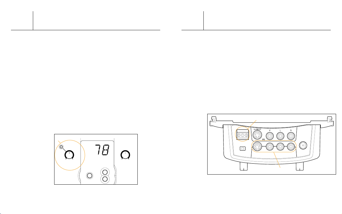
Video Input Modulation::
The MD-EM1 has adjustable video input modulation.
The LED is set to light when the modulation input level
reaches 87.5%. To effectively set the video input
modulation level, rotate the knob slowly clockwise
until the LED becomes lit. Then, rotate it slightly
counter-clockwise, until the LED goes off, for
optimal results. See fig. 2a.
Fig. 2
a
Video Present Relay::
Your MD-EM1 comes equipped with a video present relay.
This can be connected directly to an a/v control system.
This contact is normally closed, and opens upon detection
of a video signal. See fig. 3a.
Loop Through Outputs::
Video can be fed to your MD-EM1 through standard
composite cables or through S-video cables. There are
also loop through outputs which enable you to connect the
source input to another device. When using the loop
through outputs, be sure to change the resistance switch
to "1K Ω ." See fig. 3b.
4
a
b
Fig. 3
3
VIDEO
VIDEO
MODULATION LEVEL
MODULATION LEVEL
TV
STD
HRC
IRC
OFFSET MODE
CHANNEL SELECT
UP
25dBmV
OUTPUT LEVEL
35dBmV
NONO NCNC CC
VIDEO PRESENTVIDEO PRESENT
S-VIDEOS-VIDEO RF-OUTRF-OUT
VV RRLL7575 OO 1K1KOO
OUT
 Loading...