

T2 MD-4 Owner's Manual

System Set-up::
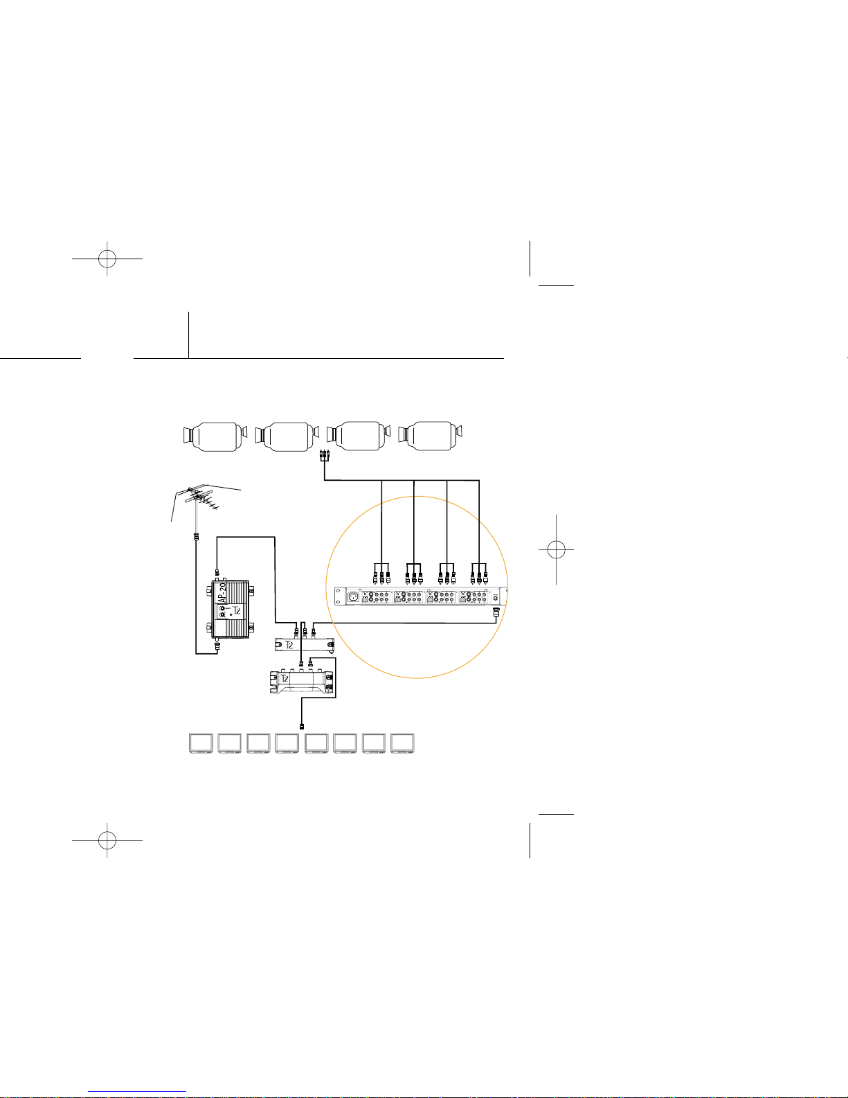
SP-8
SP-2
ANTENNA/CATV
TVs
CCTV CAMERAS
MD-4
2
The diagram below shows how the MD-4 might fit into a
typical RF system. See fig 1.
Fig. 1
Features::
Your MD-4 is a dual sideband modulator. When selecting a
channel for modulation, ensure that that channel, along
with the following channel, is empty.
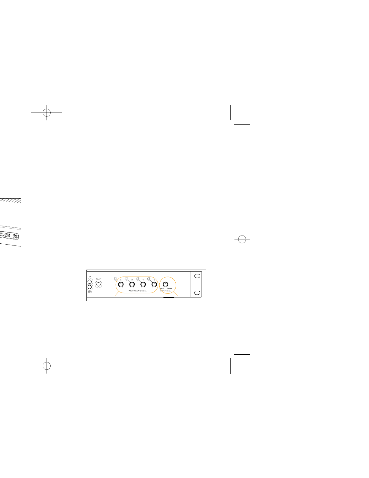
Your MD-4 has an adjustable output gain, allowing you to
quickly and easily balance the modulated channel with the
rest of the system. See fig. 3a.
Your MD-4 comes with adjustable video input modulation,
which will ensure compatibility with all video source
equipment and provide optimal video quality. Video
modulation knobs have corresponding LEDs, which are
set to illuminate when the modulation level reaches
87.5%. To effectively set the input modulation level, rotate
the knob slowly clockwise until the LED illuminates. Then
rotate it a very small amount counter-clockwise until the
LED extinguishes for optimal result. See fig. 3b.
Your MD-4 comes equipped with a video present relay.
This can be connected directly to an a/v control system.
The contact is normally closed and opens upon detection
of a video signal. See fig. 4a.
4
Fig. 3
b
a
 Loading...