

Page 1

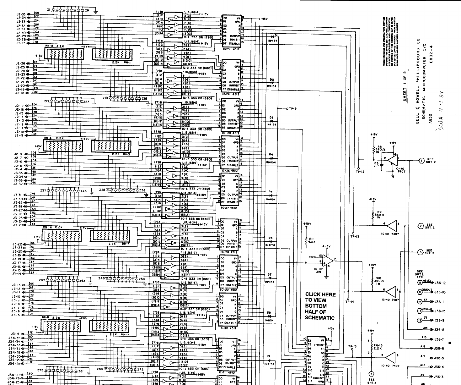
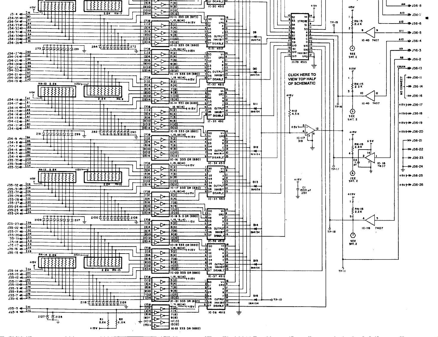
9995 INPUT/OUTPUT I/O SUPPORT DOCUMENTATION
E832-4 (SHEETS 1 AND 2)
This schematic was scanned into electronic format. To
retain clarity, each schematic is two pages.
Bookmarks will take you to each series of connectors,
and Links have been added wherever common
connections have been noted.
1/19/94
Page 2
Page 3
Page 4

Page 5

Page 6

SILENT 700 EMULATION DOCUMENTATION
This document is a step by step procedure for using a personal computer as a 9995 debugging tool. This
procedure uses the standard Windows Terminal Emulation program.
1. A file has been saved on the server titled 9995.trm. This terminal program is on the Insite System
under the Insite Utilities program group titled 9995 Communications with associated “I”-con. This
file can be found under the directory MM111 on the “C” drive on the Insite computers. This file is
also on the Service drive (S:\APPLSUPT\S700.TRM) in the Allentown facility. This file has the proper
settings for communicating with the 9995 computer.
2. Connect the nine (9) pin female side of the connector to the PC. Connect the twenty five (25) pin
female side to the J37 on the 9995 using the proper cable configuration. (See cable configuration #1)
3. Access the windows “Terminal Emulation” program.
4. Click on File and select Open. Choose the 700.TRM file.
5. Get the machine to the state where the use of the Silent 700 is desired. The machine should not be
running when using the Silent 700. The CRT should be in the “Main Menu” screen.
6. On the 9995 board, put the “normal/service” slide switch in the “service” position.
7. On the 9995 board, press the NMI button. The PC will display the following message or a similar
message depending on the debugger version. This message will indicate the PC is communicating
with the 9995.
A06 Debug 2.2
(C) 1991, BELL&HOWELL
8. If this message or a similar one doesn’t appear on the PC, repeat steps 2 through 7.
9. The machine is now in the debugging service mode. Debug commands can be entered via the PC.
These commands will be given by Technical Support or Software Engineering.
Following is the windows “Terminal” settings to be used if you have to enter them manually. Select
settings.
Terminal Emulation settings Terminal Preferences Communications
DEC VT-100 (ANSI) Line Wrap (on) Baud Rate = 300
Local Echo (off) Data Bits = 7.
Binary Transfers Sound (on) Stop Bits = 1
XModem/CRC Columns = 80 Parity = Odd
Cursor = Block & Blink Flow Control = None
Text Transfers Terminal Font = Terminal 12 Parity Check (off)
Flow Control = Standard Translations = None Carrier Detect (off)
Word Wrap Outgoing (on) Show Scroll Bars (on)
Text at Column = 79 Use Function Arrow (on) Modem Commands
Buffer Lines = 100 Dial: Prefix: ATDT
Function Keys Hangup: Suffix: ATH
None Hangup: Prefix: +++
Modem Defaults =Hayes
Printer Echo (off) Timer Mode (off)
Show Function Keys (off) Connector = Selected comm port per PC
Page 7

Silent 700 Emulation
Page 2 of 2
Silent 700 Cable Configuration
9 pin (female) PC side Communications 25 pin (female) 9995 side
Line
PIN 1 DCD PIN 8
PIN 2 TxD PIN 3
PIN 3 RxD PIN 2
PIN 4 DTR PIN 11
PIN 5 GROUND PIN 7
PIN 6 DSR PIN 6
PIN 7 RTS PIN 4 or no connection
PIN 8 CTS PIN 5
PIN 9 RI no connection
Contact Worldwide Technical Support at 1-800-811-6260 with an questions.
File: S:\applsupt\s700.doc
Page 8

 Loading...