

SZKTDZ KT-LCD6 User Manual
用户手册
User Manual
KT-LCD6 eBike Special Meter
WWW.SZKTDZ.COM

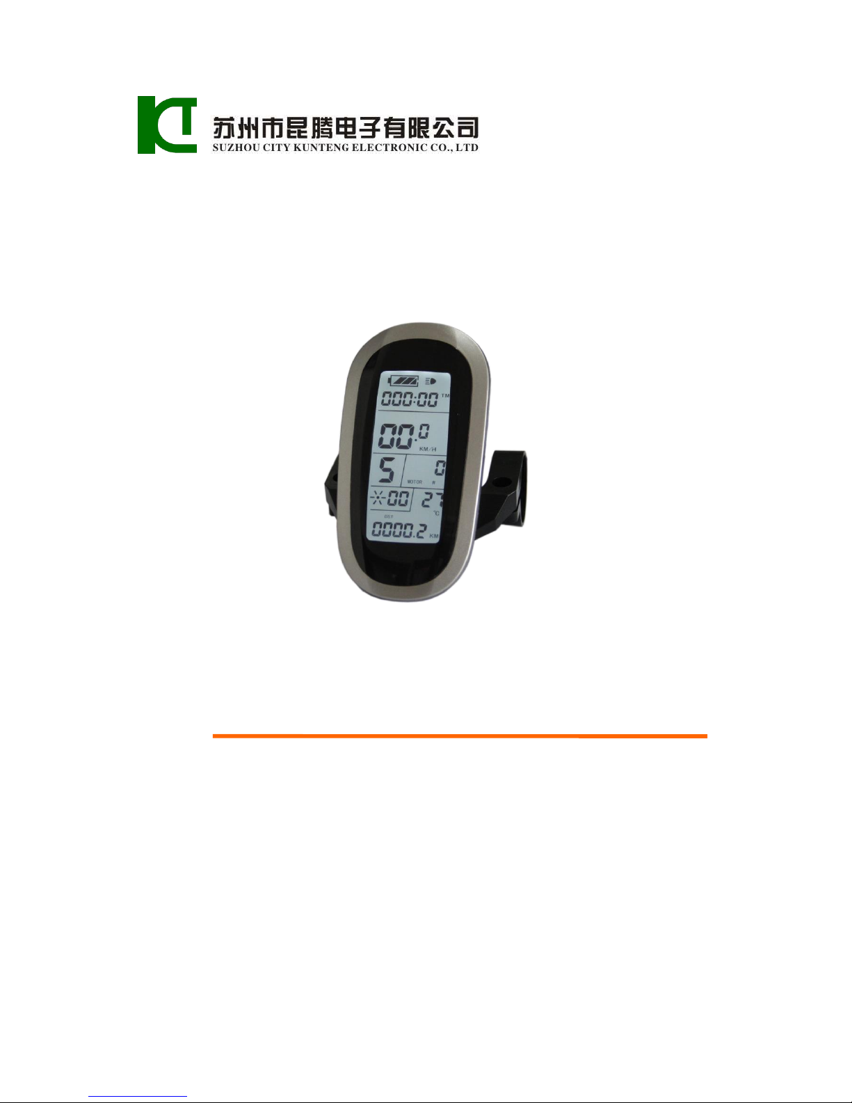
ELECTRIC BICYCLE METER KT—LCD6 Product User Manual
- 1 -
Contents
Preface……………………………………………………………………………..………. 4
Outlook and Size…………………………………………………………………………... 4
Meter Dimension …………………………………………………………………… 4
Button Box Dimension……………………………………………………………….. 4
Main Material and Color………………………………………………….………...... 5
Wiring Schematic……………………………………………………………….……. 5
Installation Instruction……………………………………………………………….…….. 5
Φ 31.8 handlebar diameters install icon………………………………………..….… 5
Φ 22.2 handlebar diameters install icon……………………………………….….…. 5
Physical installation icon............................................................................................. 6
Function Overview……………………………………………………………………..….. 6
Display Content…………………………………………………………………….….…... 7
Button Definition…………………………………………………………………….….…. 7
Normal Operation………………………………………………………………………...... 7
On/Off…………………………………………………………………………........... 7
Display Interface………………………………………………………….….……..... 8
Display of Turned on Throttle……………………………………………………..... 10
Display of Power-assist Startup…………………………………………………….. 10
Cadence Display…………………………………………………………………..… 10
PAS Ratio (or Throttle) Gear Switch……………………………….……………. 11
Push Function…………………………………………………………..…………… 12
Cruise Function…………………………………………………………………...… 12
Turn On/Off Backlight…………………………………………………….………... 13
Brake Status Display…………………………………………..…………….……… 13
Battery Capacity Indicator……………………………………..………………..........14
Motor Power and Temperature.....................................................................................15
Environment Temperature…………………………………………………………... 16
Single Data Clearing……………………………………………………………….... 16

ELECTRIC BICYCLE METER KT—LCD6 Product User Manual
- 2 -
Automatic Prompt Interface……………………………………………………..….. 17
Error Code Display…………………………………………………….…........ 17
Motor Operating Temperature Alarm……………………………………......... 17
User Project Setting……………………………………………………………………..... 18
General Project Setting…………………………………………………………………… 18
Maximum Trip Speed………………………………………………………….......... 18
Wheel Diameter…………………………………………………………………..…. 19
Metric and Imperial Units…………………………………………………………... 19
Exit General Project Setting……………………………………………………….... 20
P Parameter Setting……………………………………………………………….…….... 21
P1 Motor Characteristic Parameter Setting ............................................................... 21
P2 Wheel Speed Pulse Signal Setting ....................................................................... 21
P3 Power Assist Control Mode Setting ...................................................................... 22
P4 Throttle Startup Setting ..................................................................................... 23
P5 Power Monitoring Setting ..................................................................................... 24
Exit P Parameter Setting ............................................................................................. 24
C Parameter Setting ............................................................................................................ 25
C1 Power-assist Sensor and Parameter Selection Setting ......................................... 25
C1 Additional Parameter Setting........................................................................ 26
C2 Motor Phase Classification Coding Setting .......................................................... 27
C3 Power-assist Ratio Gear Initialization Setting ..................................................... 27
C4 Throttle Function Setting .................................................................................. 28
C5 Controller Maximum Current Adjustment Setting ............................................... 30
C6 Backlight Brightness Adjustment Setting ............................................................. 31
C7 Cruise Function Setting ........................................................................................ 32
C8 Motor Operating Temperature Display Setting .................................................... 33
C9 Power-on Password Setting .................................................................................. 33
C10 Automatic Restore Default Setting ..................................................................... 35
C11 Attribute Selection Setting .................................................................................. 36
C12 Controller Minimum Voltage Adjustment Setting ............................................. 37

ELECTRIC BICYCLE METER KT—LCD6 Product User Manual
- 3 -
C13 ABS brakes of the controller and parameters of anti-charge control Setting ......38
C14 Power-assist Tuning Parameters Setting .............................................................39
Exit C Parameter Setting............................................................................................. 40
Parameter Copy .................................................................................................................. 40
User Setting Note ............................................................................................................... 42
Version Information……………………………………………………………………… 42
ELECTRIC BICYCLE METER KT—LCD6 Product User Manual
- 4 -
Preface
The illustrated manual will help you understand and be familiar with the meter
function, guiding you on how to operate the meter, how to set the project parameters, how
to achieve the best match of the three as motor, controller and meter to improve electronic
control performance of the electric motor. This manual covers installation, operation,
parameter setting of the meter and how to use it properly, which help you resolve the
problems appeared in practical use.
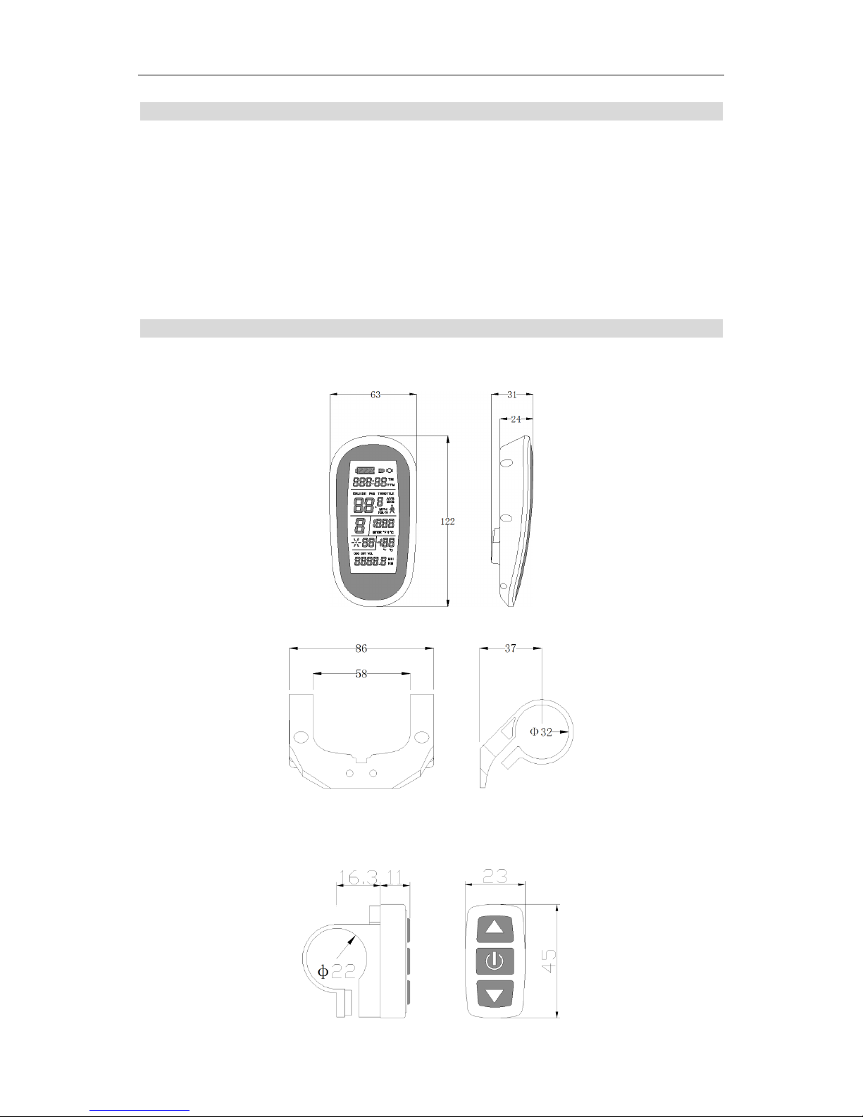
Outlook and Size
○ Meter Dimension
Meter Dimension
Dual Bracket Mounting Dimension
○ Button Box Dimension
ELECTRIC BICYCLE METER KT—LCD6 Product User Manual
- 5 -
○ Main Material and Color
PC material is mainly used for KT-LCD6 meter and button box housing, and the
housing color is silver white or black.
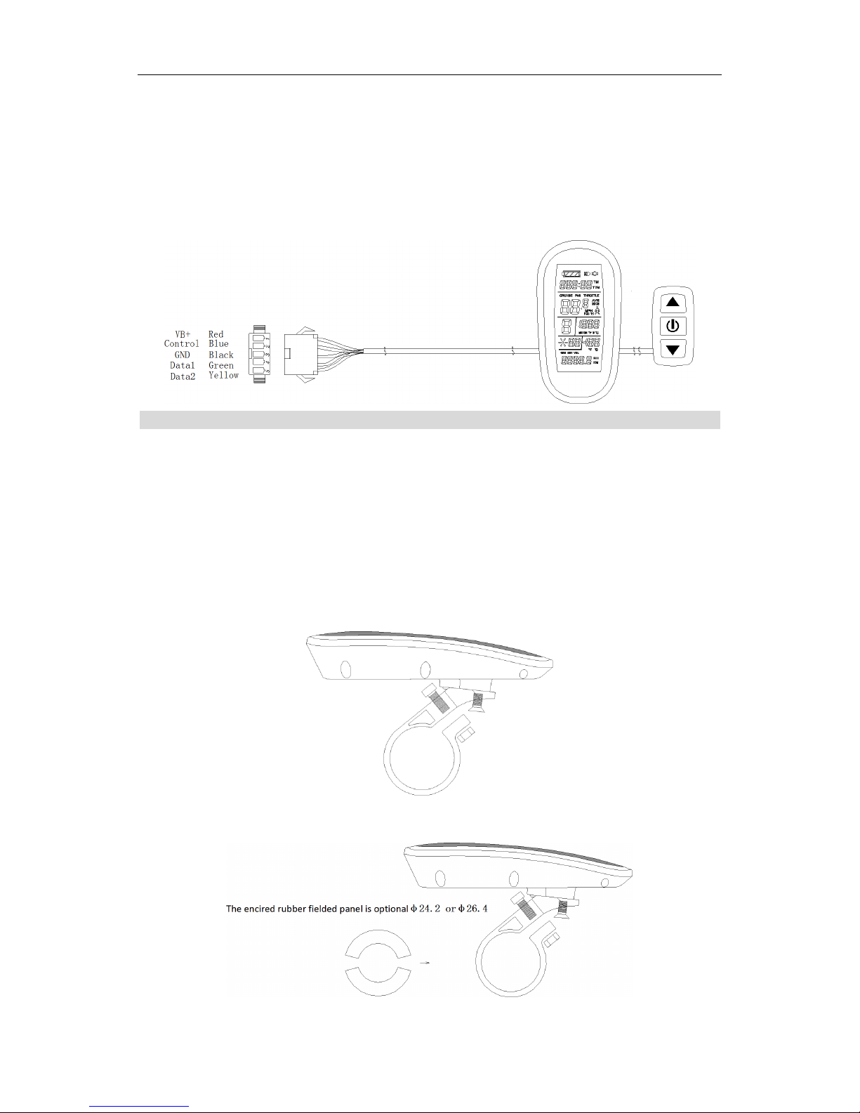
○ Wiring Schematic
Installation Instruction
The meter body and button box are mounted on the handlebars of the electric vehicle,
adjusting perspective. In the case that the vehicle is power off, the meter connectors are in
plug connection to corresponding controller connectors. Turn on the power, electric
vehicle and meter will be under normal operation, the meter installation is finished. The
protection film on meter display panel should be torn.
○ Φ 31.8 handlebar diameters install icon
○ Φ 22.2 handlebar diameters install icon
ELECTRIC BICYCLE METER KT—LCD6 Product User Manual
- 6 -
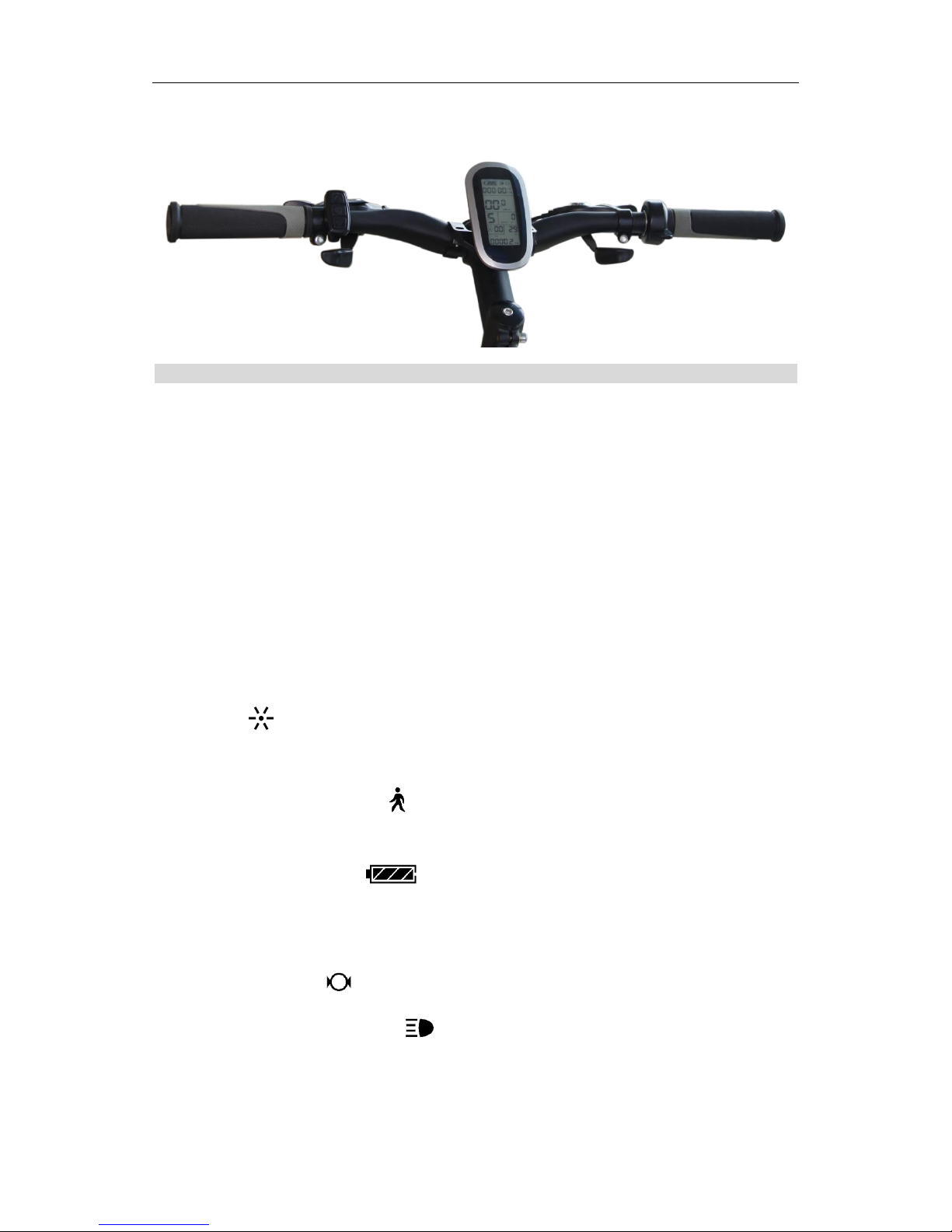
○ Physical installation icon
Function Overview
KT-LCD6 meter provide you with a variety of functions such as vehicle controls and
vehicle status digitized displays to meet the trip demands.
◇ Trip time display (with displays of a single trip time (TM) and total trip time (TTM));
◇ Trip speed display (with displays of real-time speed (KM/H or MPH) and a single
maximum speed (MXS) and a single average speed (AVS));
◇ Trip distance display (with displays of a single trip distance (DST) and total trip
distance (ODO));
◇ Display of turned on throttle (THROTTLE) ;
◇ Display of power-assist startup (PAS);
◇ Cadence ( ) display;
◇ Power assistant ratio (or throttle) gear (ASSIST) switch;
◇ 6KM/H power assistant push ( ) function;
◇ Cruise function (CRUISE);
◇ Battery capacity indicator ( );
◇ Real-time battery voltage (VOL) display;
◇ Motor power (MOTOR W) and temperature (MOTOR ℃) display;
◇ Brake status display ( );
◇ Turn on backlighting and lights ( );
◇ Environment temperature (℃ or ℉) display;
◇ Data clearing;
ELECTRIC BICYCLE METER KT—LCD6 Product User Manual
- 7 -
◇ Fault code display;
◇ User parameter setting;
◇24V, 36V, 48V supply voltage can automatic identification and be compatible.
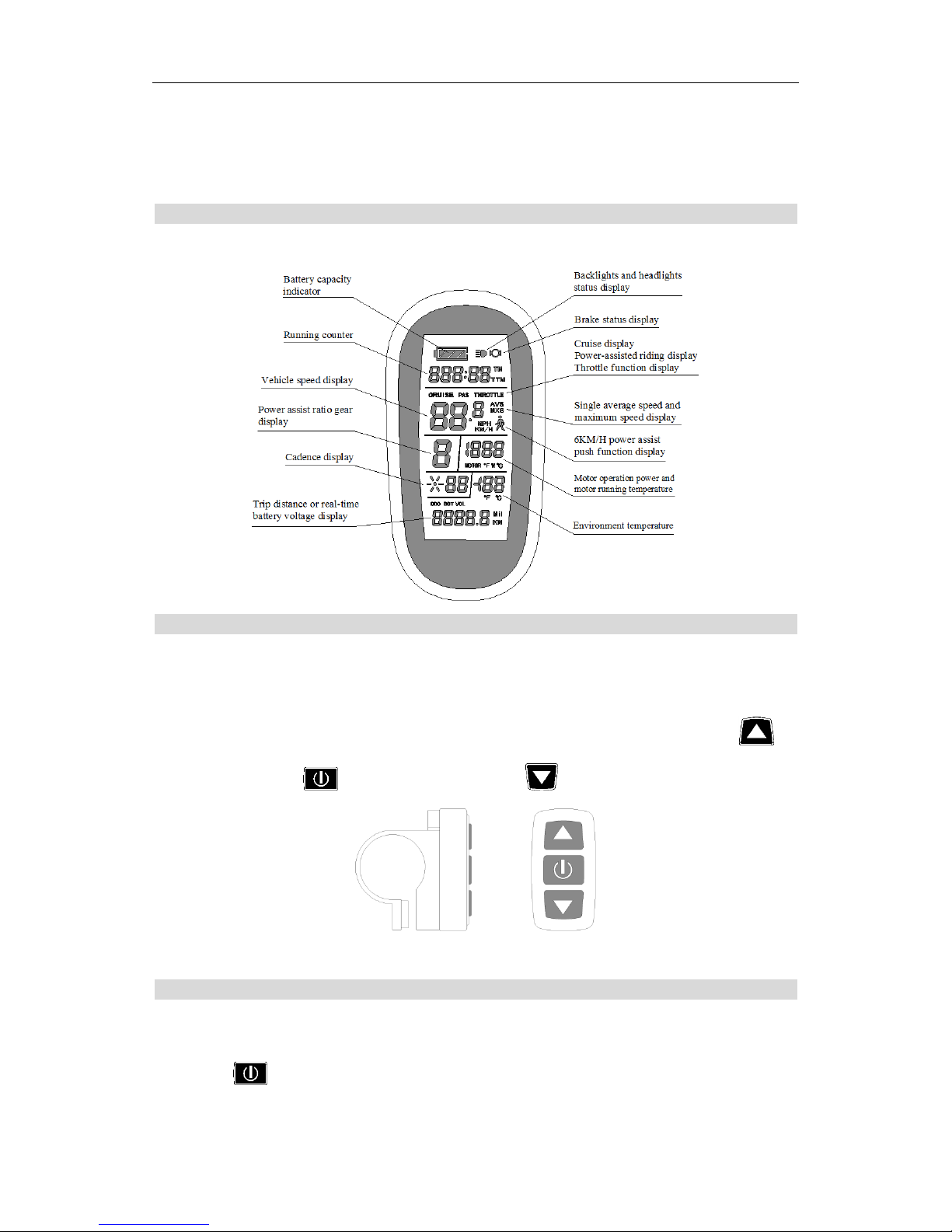
Display Content
The display content is shown as follow.
Button Definition
KT-LCD6 meter adopts the structural form with part design between the main part
and operating buttons.
There are three keys on the operating panel of button box, which are icons of
button (alt text UP), button (alt text SW) and (alt text DOWN).
Button Box and Operating Panel
Normal Operation
○ On/Off
Hold button (SW) long, the meter is powered on and into normal operation, and
ELECTRIC BICYCLE METER KT—LCD6 Product User Manual
- 8 -
it provides the controller with power supply. Under normal operating status, hold
button (SW) long, the meter is powered off, meanwhile to shutdown the power supply of
controllers. When the vehicle is stopped and without any button operation on the
meter for five minutes, the meter will automatically shut down, and the power supply
of the electric vehicle will be powered off. In power off mode, the power consumption of
the meter and controller is zero.
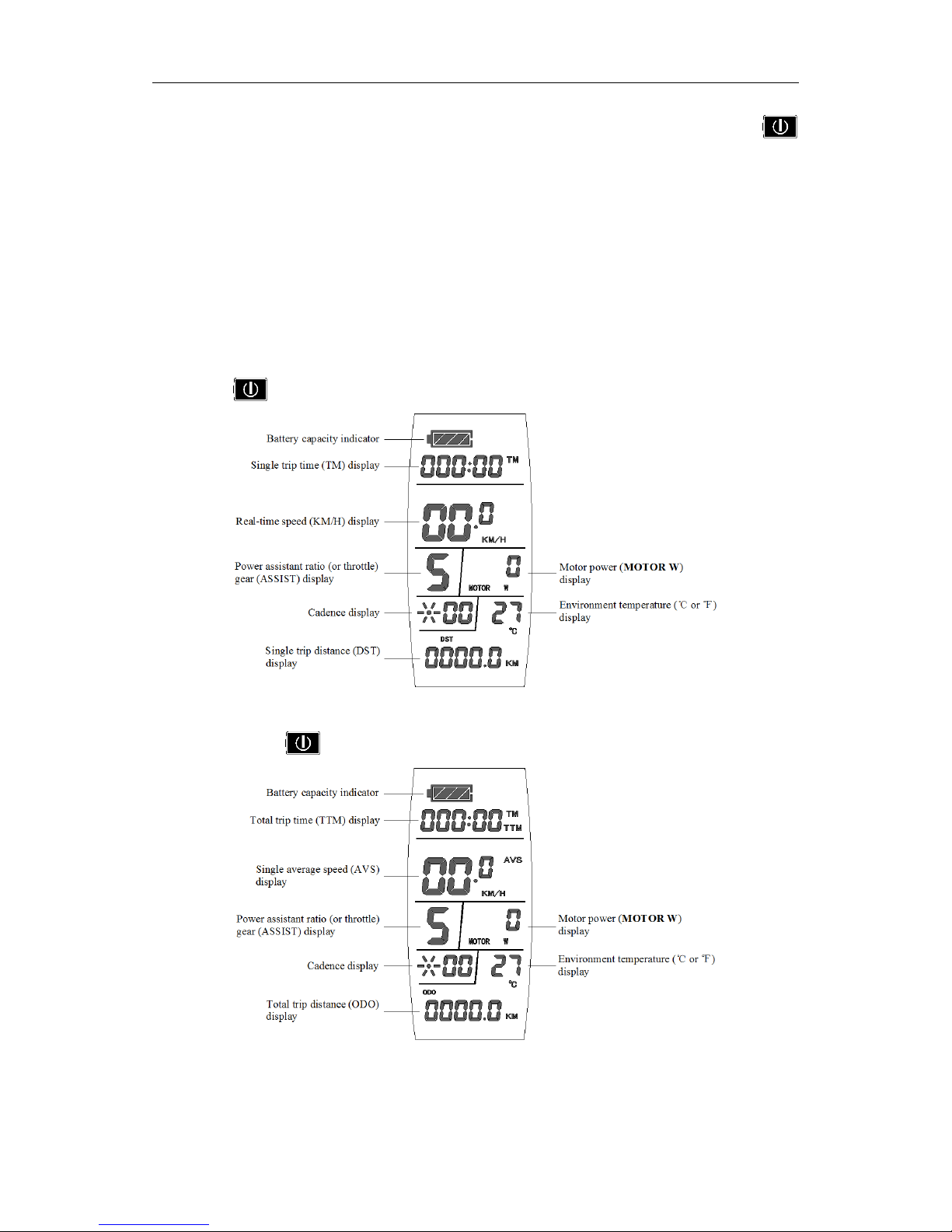
○ Display Interface
Hold button (SW) long, the meter is startup to enter display 1.
Display 1
In display 1, hold button (SW) shortly to enter display 2.
Display 2
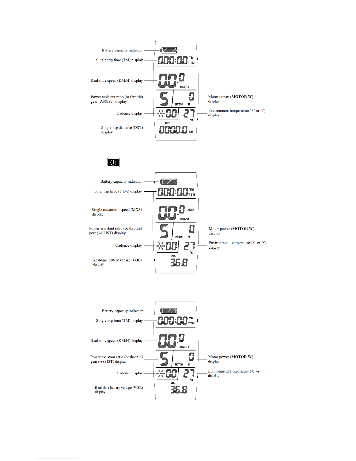
In the riding mode after 5 seconds, display 2 automatically jump to display 3.
ELECTRIC BICYCLE METER KT—LCD6 Product User Manual
- 9 -
Display 3
In display 2, hold button (SW) shortly to enter display 4.
Display 4
In the riding mode after 5 seconds, display 4 automatically jump to display 5.
Display 5
ELECTRIC BICYCLE METER KT—LCD6 Product User Manual
- 10 -
In display 4 or display 5, hold button (SW) shortly again to enter display 3.
In each display interface, if you hold button (SW) long, the meter will be
powered-off together with that of the controller.
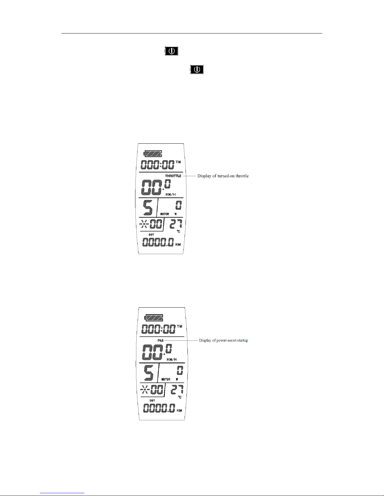
○ Display of Turned on Throttle
Rotate the throttle control handle under normal operating of the meter, the display
interface shows the logo of turned-on throttle, see the Figure below.
○ Display of power-assist startup
The meter is driving with power-assist under normal operating conditions, the display
interface flashes the power-assist startup logo (PAS) as shown in the figure.
○ Cadence Display
The meter is driving with power-assist under normal operating conditions, the display
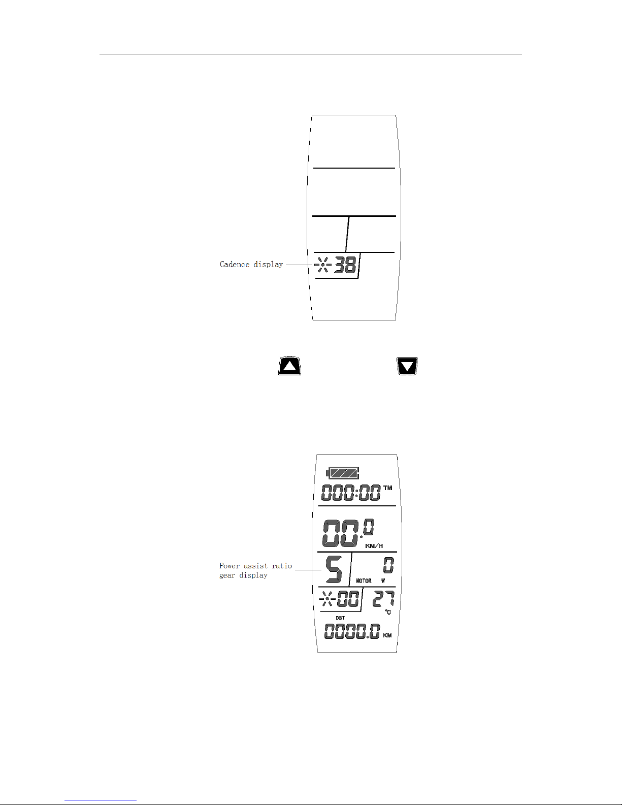
ELECTRIC BICYCLE METER KT—LCD6 Product User Manual
- 11 -
interface shows the pedal frequency per minute (turn / min) in the state of the ride, as
shown in the figure.
○ PAS Ratio (or throttle) Gear Switch
Under normal operation, hold button (UP) or button (DOWN) to
switch the power assist ratio (or throttle) gear (ASSIST), changing motor output power.
Switching range is 1-5 gear (this can also be configured according to the customer
requirements), gear 1 is for the lowest power, and gear 5 is for the highest power.
At every startup, the meter will automatically restore gear (this can also be
configured as required by users) when it was at last shut down. When the power
assist ratio is gear 0 zero, there’s no power assist function.
ELECTRIC BICYCLE METER KT—LCD6 Product User Manual
- 12 -
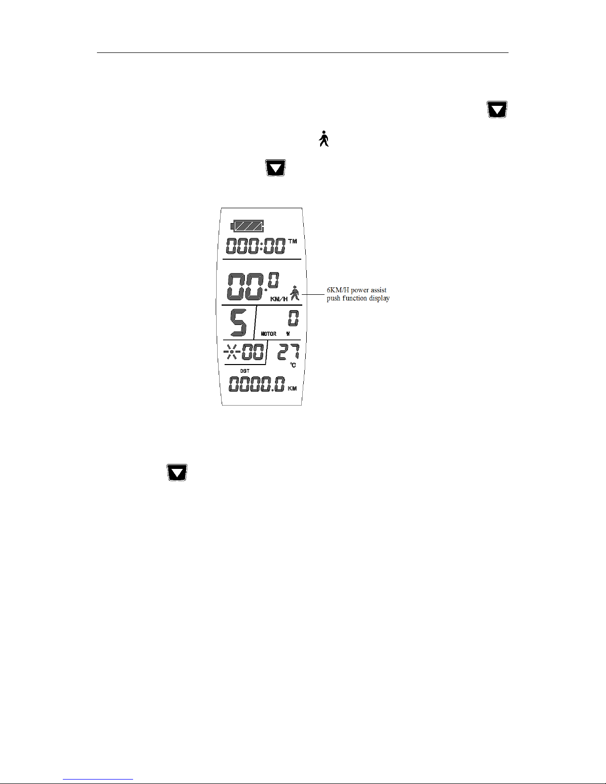
○ Power Assistant Push Function
Users can use 6KM/H power assist function when pushing vehicles. Hold
button (DOWN), the meter assist function logo ( ) flashes, the vehicle drives at the speed
of no more than 6km/h. Release button (DOWN), the assist function will be
revoked.
○ Cruise Function
When C7 parameter setting is 1 (see C parameter setting), the meter turns on cruise
function, hold button (DOWN) long to enter the cruise status when the vehicle
speed is more than 7 km/h, and the cruise function logo (CRUISE) lights. Brake or hold
any button to revoke cruise function.
 Loading...