

Page 1

DJI MATRICE 600
User Manual
V 1.0
2015.12
Page 2
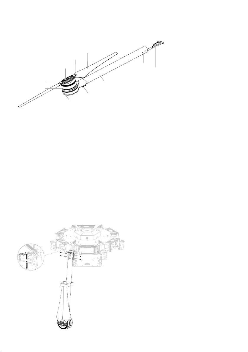
Installation
Screw
Motor
ESC Indicator
Propeller Cover
CW or CCW Mark
Propeller
Arm Screws
Arm Tube
Screw Holes
Power Cables
ESC Signal Cable
Mounting the Frame Arms
1. Preparing the frame arms.
1) Check all propellers for cracks. Ensure all the screws are secured in position.
2) Ensure all motors are mounted correctly and firmly and free from obstruction.
3) Ensure that all the cables are intact.
4) Mount all arms with red motor base to M1 and M2 (both sides of the N0.1 battery compartment) to indicate the
nose direction of the M600.
5) Identify the CW and CCW marks on the propellers. Mount the frame arms with the CCW mark to M1, M3 and M5
positions of the center frame. Mount the arms with the CW mark to M2, M4 and M6 positions of the center frame.
2. Insert the frame arm into the arm connector on the center frame with the propeller outwards. Rotate the frame arm
to align the screw holes on the frame arm and the connector. Then insert and tighten four M3x6.5 screws.
3. Pull the cables of the frame arm through the arm stopper and the wire outlet on the lower plate of the center frame.
Then insert the stopper into the arm connector.
4. Gently lift the frame arm.
©2015 DJI. All Rights Reserved. 2
Page 3

5. Twist the red knob to lock each arm in place. Be sure there is an audible click, which indicates a proper lock. Check
Power Cables
Power Cables
Cable Fixing Ring
ESC Signal Cable
ESC Signal Cable
Lower Cover of the Center Frame
the arm for movement. To store, untwist the knob and lower the frame arm.
6. Remove the lower cover of the center frame to connect the power cables and the ESC signal cable.
7. Pull all the cables of the frame arm through the cable fixing ring on bottom of the center frame.
8. Plug each ESC signal cable into the slot near each arm on the center frame.
9. Connect the power cables to the center frame. Each cable must be screwed into a positive (+) or negative (-) gold
bracket. Each bracket will have two cables of the same color screwed into it. Red cables are positive and black
cables are negative.
10. Ensure all ESC cables, and power cables are correctly installed onto the center frame.
11. Double check all frame arms. Frame arms M1 and M2 are the forward facing (nose direction), frame arms M4 and
M5 are facing backward. Seen from the top, motors on arms M1, M3 and M5 rotate counter clockwise while those
on arms M2, M4 and M6 rotate clockwise.
©2015 DJI. All Rights Reserved. 3
Page 4
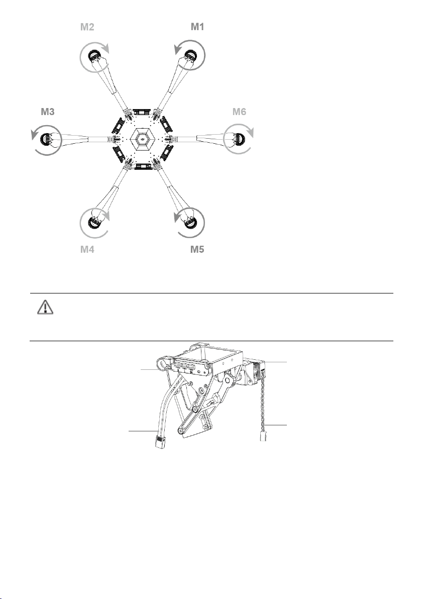
DO NOT mix the mounting position between the left and right servo set. Identify the left servo set by
locating the control board that is integrated on the left servo set.
Control Board
(Left servo set only)
Servo
Mounting the Servo Set
Power Cable
Servo Cable
1. Insert the servo mounting rod into the outer mounting hole on the center frame, mounting holes on the servo set
and inner mounting hole on the center frame respectively. Ensure that the left servo set is mounted on the left hand
side (seeing from tail)of the aircraft.
2. Align the screw holes of the connector on the center frame and the screw holes on the middle of the servo set.
Insert and tighten two M3x6.5 screws (thumb).
©2015 DJI. All Rights Reserved. 4
Page 5
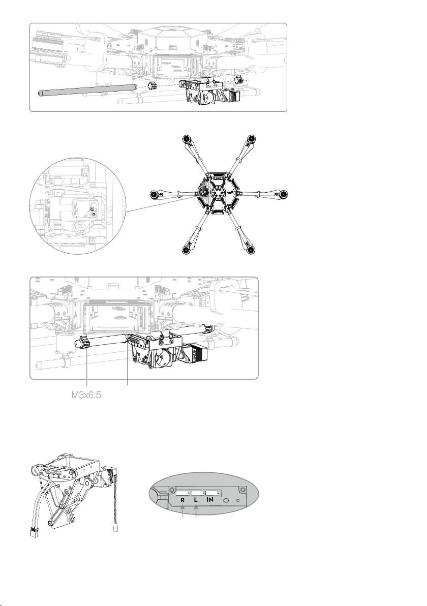
M3x6.5
Right Servo Cable
Left Servo Cable
3. Align the cable fixing ring and the screw holes on the bottom of the servo set. Tighten the M3x5 screws.
4. Tighten the M3x6.5 screws to secure the servo set on the mounting rod.
5. Connecting the Servo Cables.
1) Connect the left servo cable to “L” port on the control board.
2) Connect the right servo cable to “R” port on the control board.
©2015 DJI. All Rights Reserved. 5
Page 6
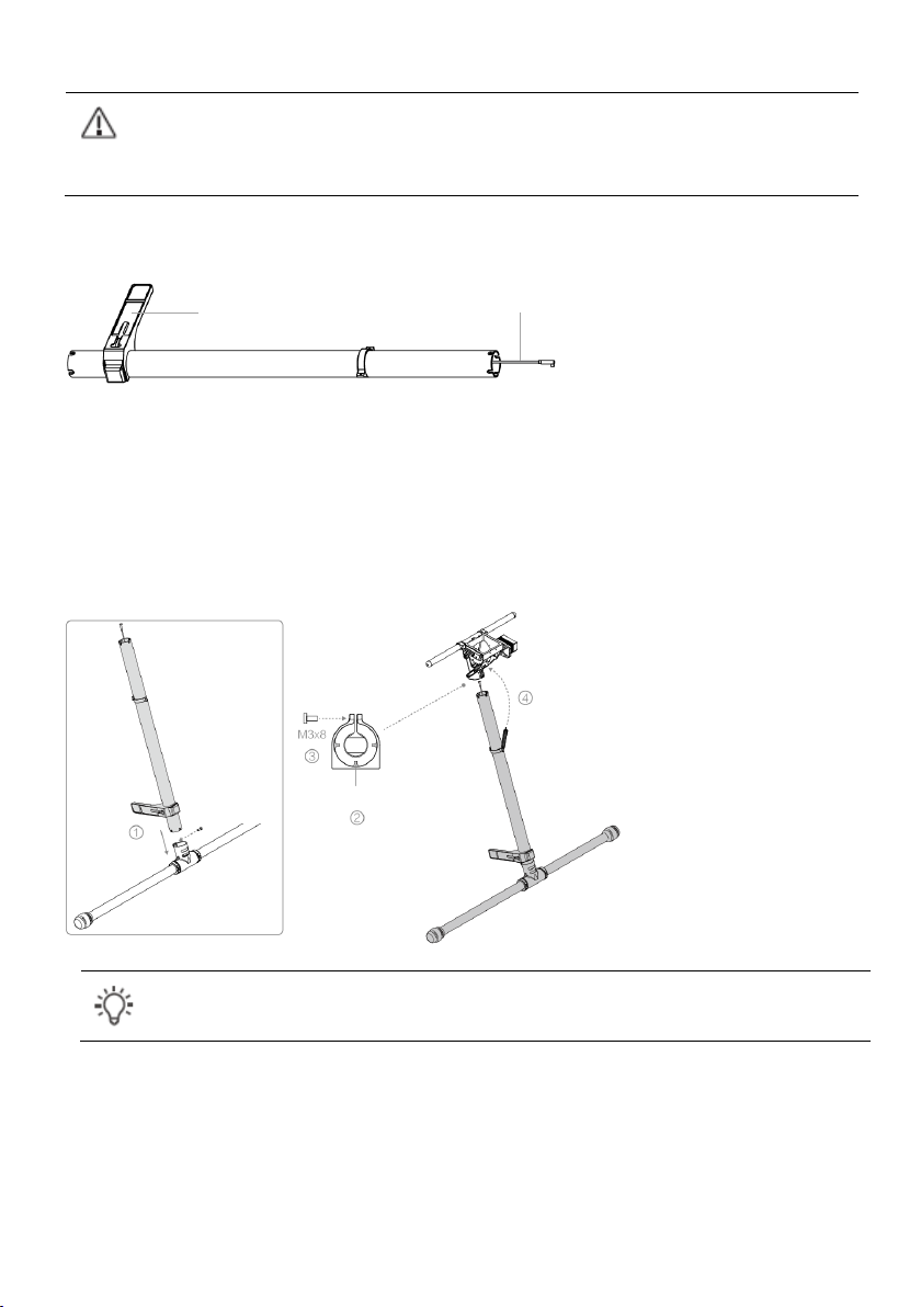
Mounting the Landing Gear
Do not mix the cabling between the left and right servo, otherwise the landing gear cannot function
properly.
Arrange the wiring neatly to avoid the cables being cut by frame edges.
Note the initial length of spring is 58.5 mm and it is stretched to 70 mm in its final position.
Antenna
Antenna Cable
Fins in the connector
M3x8
(Socket cap)
The antennas are attached to the landing gears on its delivery. Pull out the antenna cables from the landing gear legs
before mounting.
1) Insert one landing gear leg into each landing skid tube and secure it in place by tightening the M3× 8 (socket cap)
screw.
2) Insert the landing gear leg into the connector on the servo set. DO NOT damage the antenna cable.
3) Rotate the landing gear leg until its slots are aligned to the fins in the connector. Then tighten the M3x8 screws on
the connector.
4) Connect both springs on the legs to the center frame.
Mounting the Lightbridge 2 Air System
1. Remove the upper cover of the center frame, four M3x6.5 screws (thumb), mounting plate and the flight controller.
©2015 DJI. All Rights Reserved. 6
Page 7
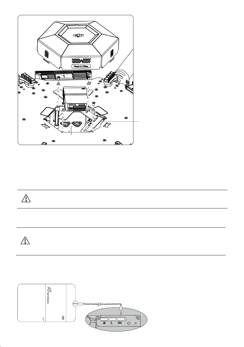
If using the AV / HDMI port of the Lightbridge 2 air system, connect the corresponding cables first.
Install the antennas before powering on the Air System.
When connecting the antennas, ensure the connector pin is aligned with the port hole, and DO NOT
apply excessive force to avoid damaging the pin.
Lightbridge 2 Air System
Wire Outlets
2. Open the fixing bracket and then remove the Lightbridge 2 air system.
3. Pull the two antenna cables from the triangular wire outlets (between M4 and M5) on the lower plate of the center
frame. Connect them to the antenna ports on the Lightbridge 2 air system.
4. Mount the Lightbridge 2 air system back into the bracket. DO NOT damage the antenna cables.
5. Connect the Micro USB cable on back of the Aircraft Status Indicator to the Micro USB port of the Lightbridge 2
air system.
Mounting the Flight Controller
1. Connect the F1 port of the flight controller to the “IN” port of the landing gear control board via the servo cable.
©2015 DJI. All Rights Reserved. 7
Page 8
2. Connect the servo cables from No.1 to No.6 to the corresponding port of the flight controller. Connect the No.7
Use the included DBUS cable ONLY. Otherwise the Lightbridge 2 air system cannot function properly.
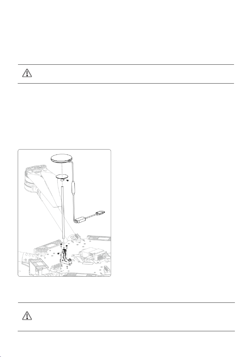
Mount the GPS with an extension rod to avoid interference from the center frame power board.
Ensure the extension rod is firm and stable before every flight.
Avoid catching your fingers in the collapsible mount when folding for transportation.
servo cable to the M7 port of the flight controller. Connect the No.9 servo cable to the iESC port of the flight
controller.
3. Connect the Aircraft Status Indicator cable to the LED port of the flight controller.
4. Connect the DBUS port of the Lightbridge 2 air system to the RF port of the flight controller via the DBUS cable.
5. If using a DJI gimbal, refer to the corresponding user manual for more information on how to connect.
6. Re-mount the flight controller mounting plate with four M3x6.5 screws (thumb).
Mounting GPS Module
1. Attach the collapsible GPS mount to one side of the center frame using M2.5×8 screws.
2. Mount a GPS module to the GPS mount with a strut. Ensure the arrow points toward the nose (M1, M2). Insert two
M2x4 screws into the two connectors above and under the extension rod.
3. Attach the CAN HUB of the GPS module onto the plate of the center frame.
4. Plug the CAN cable into the CAN1 port on the flight controller.
©2015 DJI. All Rights Reserved. 8
Page 9

Mounting the Upper and Lower Covers of the Center Frame
1. Re-mount the upper cover of the center frame. Note that the arrow points toward the nose (M1, M2) and DO NOT
damage the cables.
2. Re-mount the lower cover of the center frame. Note that the two square holes are aligned to the two XT30 ports
on the lower plate of the center frame. DO NOT damage the cables.
3. Connect the servo power cable to the XT30 port (6S LiPo) on the lower plate of the center frame.
©2015 DJI. All Rights Reserved. 9
Page 10

Intelligent Flight Battery
There are six battery compartments on the M600. Six intelligent flight batteries are required to fly
the aircraft.
It’s strongly recommended to fully charge all the intelligent flight batteries before using them
together.
Power Button
(Built-in LED)
Installing the Battery
Insert the six Intelligent Flight Batteries into the battery compartments.
Powering ON/OFF
Powering On: Press the Power Button once, then press again and hold for 2 seconds to power on. The Power LED
will turn red and the Battery Level Indicators will display the current battery level.
Powering Off: Press the Power Button once, then press again and hold for 2 seconds to power off.
The M600 has six intelligent flight batteries and advanced battery management system. When powering on one of
the batteries, the battery management system will read all batteries’ information and judge the power supply
conditions. If the power supply is OK, other batteries will power on automatically. Otherwise, there will be a prompt
on the DJI GO app. Power off just one of the batteries, and then other batteries will power off automatically.
If there is a prompt on the DJI GO app, follow the tips to adjust your batteries.
©2015 DJI. All Rights Reserved. 10
Page 11

Remote Controller
Preparing Remote Controller
Tilt the Mobile Device Holder to the desired position then adjust the antenna as shown.
Remote Controller Diagram
[1] Antennas
Relays aircraft control and video signal.
[2] Mobile Device Holder
Mounting place for your mobile device.
[3] Control Stick
Controls aircraft orientation.
[4] Return Home (RTH) Button
Press and hold the button to initiate Return to Home (RTH).
[5] Transformation Switch
Toggle the switch up or down to raise of lower the landing gear.
[6] Battery Level LEDs
Displays the current battery level.
©2015 DJI. All Rights Reserved. 11
Page 12

[7] Status LED
Displays the power status.
[8] Power Button
Used to power on or power off the remote controller.
[9] RTH LED
Circular LED around the RTH button displays RTH status.
[10] Camera Settings Dial
Turn the dial to adjust camera settings. Only functions when the remote controller is connected to a mobile
device running the DJI GO app.
[11] Playback Button
Playback the captured images or videos.
[12] Shutter Button
Press to take a photo. If in burst mode, the set number of photos will be taken with one press.
[13] Flight Mode Switch
Used to switch between P, A and F mode.
[14] Video Recording Button
Press to start recording video. Press again to stop recording.
[15] Gimbal Dial
Use this dial to control the tilt of the gimbal.
[16] Micro USB Port
Reserved.
[17] SDI Port
Connect a SDI display device.
©2015 DJI. All Rights Reserved. 12
Page 13

[18] HDMI OUT Port
Connect an HD compatible monitor.
[19] USB Port
Connect to mobile device to access all of the DJI GO app controls and features.
[20] GPS Module
Used to pinpoint the location of the remote controller.
[21] Back Left Button
Customizable button in DJI GO app.
[22] Back Right Button
Customizable button in DJI GO app.
[23] Power Port
Connect to a power source to charge the remote controller’s internal battery.
Remote Controller Operations
Powering On and Off the Remote Controller
The M600 remote controller is powered by a 2S rechargeable battery with a capacity of 6000mAh. The battery
level is indicated by the Battery Level LEDs on the front panel. Follow the steps below to power on your remote
controller:
1. When powered off, press the Power Button once and the Battery Level LEDs will display the current battery level.
2. Then, press and hold the Power Button to power on the remote controller.
3. The Remote Controller will beep when it powers on. The Status LED will blink green (slave remote controller
blinks solid purple) rapidly, indicating that the remote controller is linking to the aircraft. The Status LED will show a
solid green light when linking is completed.
4. Repeat step 2 to power off the remote controller after finish using it.
©2015 DJI. All Rights Reserved. 13
Page 14

Charging Remote Controller
Charge the remote controller via supplied charger.
Controlling Camera
Shoot videos or images and adjust camera settings via the Shutter Button, Camera Settings Dial, Playback Button
and Video Recording Button on the remote controller.
[1] Camera Settings Dial
Turn the dial to quickly adjust camera settings such as ISO and shutter speed without letting go of the remote
controller. Move the dial button to left or right to view the pictures or videos in playback mode.
[2] Playback Button
Press to view images or videos that have already been captured.
[3] Shutter Button
Press to take a photo. If burst mode is activated, multiple photos will be taken with a single press.
[4] Recoding Button
©2015 DJI. All Rights Reserved. 14
Page 15

Press once to start recording video, then press again to stop recording .
Status LED
Strong
Weak
Optimal Transmission Range
RTH LED
Connecting Mobile Device
1. Press the button on the side of the Mobile Device Holder to release the clamp, adjust it to fit then attach your
mobile device.
2. Connect your mobile device to the remote controller with a USB cable.
3. Plug one end of the cable into your mobile device, and the other end into the USB port on the back of the remote
controller.
Optimal Transmission Range
The signal transmission between aircraft and remote controller perform best within the range that displayed in the
picture shown below:
Ensure the aircraft is flying within the optimal transmission range. Adjust the distance and position between the
operator and the aircraft to achieve optimal transmission performance.
Remote Controller LED
The Status LED reflects connection status between Remote Controller and aircraft. The RTH LED shows the Return
to Home status of the aircraft. The table below contains details on these indicators.
©2015 DJI. All Rights Reserved. 15
Page 16

Status LED
Alarm
Remote Controller Status
— Solid Red
chime
The remote controller is not connected with the aircraft.
— Solid Green
chime
The remote controller is connected with the aircraft.
Blinking Red
D-D-D......
Remote controller error.
Red and Green/ Red and
Yellow Alternate Blinks
None HD Downlink is disrupted.
RTH LED
Sound
Aircraft Status
— Solid White
chime
Return to Home procedure begins.
Blinking White
D . . .
Sending Return to Home command to the aircraft.
Blinking White
DD .. .. ..
Aircraft Return to Home in progress.
©2015 DJI. All Rights Reserved. 16
Page 17

DJI GO App
When connecting to the aircraft for the first time, ensure your mobile device is connected to the internet
and follow the instructions to set up the app.
Use this app to control the gimbal, camera and other features of your flight system. The app also comes with the
Library, Explore, and Me sections for configuring your aircraft and sharing your content with friends. It is
recommended that you use a tablet for the best experience.
Equipment
On the Equipment page, you can enter Camera View, visit the Academy or view your flight records.
Camera View
[1] Flight Mode
: The text next to this icon indicates the current flight mode.
Tap to enter MC (Main Controller) settings. Modify flight limits, perform compass calibration, and set the gain
values on this screen.
[2] GPS Signal Strength
: This icon shows the current strength of GPS signals. Green bars indicates adequate GPS strength.
[3] System Status
: This icon shows current aircraft system status, such as GPS signal health.
[4] Battery Level Indicator
: The battery level indicator dynamically displays the battery level. The color zones on the battery
level indicator represent different battery levels.
[5] Remote Controller Signal
©2015 DJI. All Rights Reserved. 17
Page 18

: This icon shows the strength of remote controller signal.
[6] HD Video Link Signal Strength
: This icon shows the HD video downlink signal strength between the aircraft and the remote controller.
[7] Battery Level
: This icon shows the current Intelligent Flight Battery level.
Tap to enter battery information menu, set the various battery warning thresholds and view the battery warning
history in this page.
[8] General Settings
: Tap this icon to enter General Settings page. Select parameter uni ts, rese t the camera, enable the quick
view feature, adjust the gimbal roll value and toggle flight route display on this page.
[9] Camera Operation Bar
Function
: Tap to adjust camera settings, such as video format and digital filters.
Shutter
: Tap this button to take a single photo.
Record
: Tap once to start recording video, then tap again to stop recording. You can also press the Video
Recording Button on the remote controller, which has the same function.
Playback
: Tap to enter playback page. You can preview photos and videos as soon as they are captured.
Camera Settings and Shooting Mode
: Tap to enter the Camera Settings page and switch from camera shooting mode from manual to auto.
[10] Map
Display the flight path of the current mission. Tap to switch from the Camera GUI to the Map GUI.
[11] Flight Telemetry
©2015 DJI. All Rights Reserved. 18
Page 19

Flight Parameters:
Height: Vertical distance from home point.
Distance: Horizontal distance from home point.
Vertical Speed: Vertical flying speed.
Horizontal Speed: Horizontal flying speed.
Flight Attitude and Radar Function:
Flight attitude is indicated by the flight attitude icon.
(1) The red arrow shows which direction the aircraft is facing.
(2) Light blue and dark blue areas indicate pitch.
(3) Pitching of the boundary between light blue and dark blue area shows roll angle.
[12] Home Point Settings
: Tap this button to reset the current home point. You may choose to set the aircraft take-off location, the
remote controller’s current position, or the aircraft’s current position as the Home Point.
[13] Return to Home (RTH)
: Initiate RTH home procedure. Tap to have the aircraft return to the latest ho me point.
[14] Gimbal Operation Mode
[15] Auto Takeoff/Landing
: Tap to initiate auto takeoff or landing.
[16] Livestream
: This icon indicates the current video feed is being broadcast live on YouTube. Ensure that mobile data
service is available on your mobile device.
[17] Back
: Tap to return to the main GUI.
Library
Director is an intelligent video editor built into the DJI GO app. After recording several video clips and downloading
them to your mobile device, go to Director on the home screen. You can then select a template and a specified
number of clips which are automatically combined to create a short film that can be shared immediately.
Explore
Find out about our latest events, featured products and trending Skypixel uploads in the Explore page.
©2015 DJI. All Rights Reserved. 19
Page 20

Me
If you already have a DJI account, you will be able to participate in forum discussions, earn Credits in the DJI Store,
and share your artwork with the community.
©2015 DJI. All Rights Reserved. 2
0
Page 21

Flight
Normal
Red, Green and Yellow Flash
Alternatively
Power on and self-check
x4 Blinks Yellow Four Times
Aircraft warming up
Green Flashes Slowly
Safe to Fly (P mode with GPS)
Yellow Flashes Slowly
Safe to Fly (A mode but No GPS)
Warning
Fast Yellow Flashing
Remote Controller Signal Lost
Slow Red Flashing
Low Battery Warning
Fast Red Flashing
Critical Low Battery Warning
Red Flashing Alternatively
IMU Error
— Solid Red
Critical Error
Red and Yellow Flash Alternatively
Compass Calibration Required
Aircraft Status Indicator
Aircraft Status Indicator
Aircraft Status Indicator shows the system status of the flight controller. Refer to the table below for more information
about the Aircraft Status Indicator:
Aircraft Status Indicator Description
Starting/Stopping the Motors
Starting Motors
The Combination Stick Command (CSC) listed below are used to start the motors instead of simply pushing the stick
©2015 DJI. All Rights Reserved. 21
Page 22

up. Ensure that you perform the CSC in one motion.
DO NOT perform CSC when aircraft is in midair, otherwise the motors will be stopped.
Stopping Motors
There are two methods to stop the motors.
Method 1: When the M600 has landed, push the throttle down, then conduct CSC. Motors will stop immediately.
Release both sticks once motors stop.
Method 2: When the aircraft has landed, push the throttle down and hold. The motors will stop after 3 seconds.
©2015 DJI. All Rights Reserved. 22
Page 23

Specifications
Structure
Diagonal Wheelbase
1133.5 mm
Dimensions
Weight (with six TB47S batteries)
8810 g
Weight (with six TB48S batteries)
9320 g
Max Takeoff Weight
14.8 kg
Performance
Hovering Accuracy (P Mode)
Vertical: 0.5 m, Horizontal: 1.5 m
Max Angular Velocity
Pitch: 300°/s, Yaw: 150°/s
Max Tilt Angle
25°
Max Ascent Speed
5 m/s
Max Descent Speed
3 m/s
Max Wind Speed Resistance
8 m/s
Max Speed
Hovering Time (with six TB47S batteries)
No payload: 42 min, with payload of 6 kg: 16 min
Hovering Time (with six TB48S batteries)
No payload: 45 min, with payload of 5.5 kg: 18 min
* The hovering time data is based on no-wind environment, hovering at 10 m above the sea level until landing with a battery level
of 10%
1668 mm1517 mm749 mm (with propellers, frame arms and
GPS mount unfolded)
1133 mm 981 mm749 mm (with propellers folded, frame
arms and GPS mount unfolded)
557 mm519 mm551 mm (with propellers, frame arms and
GPS mount folded)
20 m/s (ATTI mode, no payload, no wind)
19 m/s (GPS mode, no payload, no wind)
17 m/s (ATTI or GPS mode, using six TB47S Intelligent Flight
Batteries with payload of 6 kg, no wind)
©2015 DJI. All Rights Reserved. 23
Page 24

Propulsion System
Motor Model
DJI 6010
Propeller Model
DJI 2170
ESC Model
DJI E SERIES 1240
Flight Control System
Model
A3
Other
Operating Temperature Range
-10 to 40°C
Compatible DJI Gimbals
Zenmuse X3, Zenmuse X5;
Retractable Landing Gear
Standard
Remote Controller
Operating Frequency
Transmitting Distance (unobstructed,
free of interference)
EIRP
10 dBm @ 900 m, 13 dBm @ 5.8 G, 20 dBm @ 2.4 G
Video Output Port
USB, Mini-HDMI
Power Supply
Built-in battery
Charging
DJI charger
Mobile Device Holder
Tablet or Smart Phone
Output Power
9 W
Operating Temperature Range
-10 to 40°C
Zenmuse Z15 Series HD Gimbal:
Z15-A7, Z15-BMPCC, Z15-5D III, Z15-GH4;
Ronin-M
920.6 MHz~928 MHz (Japan Only)
5.725~5.825 GHz; 2.400~2.483 GHz
FCC: 5 km
CE: 3.5 km
©2015 DJI. All Rights Reserved. 24
Page 25

Storage Temperature Range
Less than 3 months: -20 to 45°C
Charging Temperature Range
0 to 40°C
Battery
6000 mAh LiPo 2S
Max Tablet Width
170 mm
Charger
Model
A14-100P1A
Voltage
26.3 V
Rated Power
100 W
Battery (Standard)
Model
TB47S
Capacity
4500 mAh
Voltage
22.2 V
Battery Type
LiPo 6S
Energy
99.9 Wh
Net Weight
595 g
Operating Temperature Range
-10 to 40°C
Storage Temperature Range
Charging Temperature Range
0 to 40°C
Max Charging Power
180 W
Battery (Optional)
Name
Intelligent Flight Battery
Model
TB48S
Capacity
5700 mAh
More than 3 months: 22 to 28°C
Less than 3 months: -20 to 45°C
More than 3 months: 22 to 28°C
©2015 DJI. All Rights Reserved. 25
Page 26

Voltage
22.8 V
Battery Type
LiPo 6S
Energy
129.96 Wh
Net Weight
680 g
Operating Temperature Range
-10 to 40°C
Storage Temperature Range
Charging Temperature Range
0 to 40°C
Max Charging Power
180 W
Less than 3 months: -20 to 45°C
More than 3 months: 22 to 28°C
©2015 DJI. All Rights Reserved. 26
Page 27

FCC Warning Message
Any Changes or modifications not expressly approved by the party responsible for compliance could void the
user’s authority to operate the equipment.
This device complies with part 15 of the FCC Rules. Operation is subject to the following two conditions: (1)
This device may not cause harmful interference, and (2) this device must accept any interference received,
including interference that may cause undesired operation.
FCC Radiation Exposure Statement:
This equipment complies with FCC radiation exposure limits set forth for an uncontrolled environment. This
should be installed and operated with minimum distance 20cm between the radiator& your body.
M600
This transmitter must not be co-located or operating in conjunction with any other antenna or transmitter.
Note: This equipment has been tested and found to comply with the limits for a Class B digital device, pursuant
to part 15 of the FCC Rules. These limits are designed to provide reasonable protection against harmful
interference in a residential installation. This equipment generates uses and can radiate radio frequency energy
and, if not installed and used in accordance with the instructions, may cause harmful interference to radio
communications. However, there is no guarantee that interference will not occur in a particular installation. If
this equipment does cause harmful interference to radio or television reception, which can be determined by
turning the equipment off and on, the user is encouraged to try to correct the interference by one or more of
the following measures:
—Reorient or relocate the receiving antenna.
—Increase the separation between the equipment and receiver.
—Connect the equipment into an outlet on a circuit different from that to which the receiver is connected.
—Consult the dealer or an experienced radio/TV technician for help.
IC RSS Warning
This device complies with Industry Canada licence-exempt RSS standard (s). Operation is subject to the
following two conditions: (1) this device may not cause interference, and (2) this device must accept any
interference,including interference that may cause undesired operation of the device.
Le présent appareil est conforme aux CNR d'Industrie Canada applicables aux appareils radio exempts de
licence.
L'exploitation est autorisée aux deux conditions suivantes:
(1) l'appareil ne doit pas produire de brouillage, et
(2) l'utilisateur de l'appareil doit accepter tout brouillage radioélectrique subi, même si le brouillage est
susceptible d'en compromettre le fonctionnement.
©2015 DJI. All Rights Reserved. 27
Page 28

IC Radiation Exposure Statement:
This equipment complies with IC RF radiation exposure limits set forth for an uncontrolled environment. This
transmitter must not be co-located or operating in conjunction with any other antenna or transmitter.
This should be installed and operated with minimum distance 20cm between the radiator& your
M600
body.
Any Changes or modifications not expressly approved by the party responsible for compliance could void the
user’s authority to operate the equipment.
KCC Warning Message
“해당무선설비는 운용 중 전파혼신 가능성이 있으므로 인명안전과 관련된 서비스는 할 수 없습니다.”
“해당 무선설비는 운용 중 전파혼신 가능성이 있음”
NCC Warning Message
Administrative Regulations on Low Power Radio Waves Radiated Devices warning:
Article 12
Without permission granted by the NCC, any company, enterprise, or user is not allowed to change
frequency, enhance transmitting power or alter original characteristic as well as performance to an approved
low power radio-frequency devices.
Article 14
The low power radio-frequency devices shall not influence aircraft security and interfere legal
communications; If found, the user shall cease operating immediately until no interference is achieved.
The said legal communications means radio communications is operated in compliance with the
Telecommunications Act.
The low power radio-frequency devices must be susceptible with the interference from legal communications
or ISM radio wave radiated devices.
©2015 DJI. All Rights Reserved. 28
 Loading...