

Page 1
LIGHTBRIDGE 2
User Manual
V1.0 2015.9
Page 2

Disclaimer
Thank you for purchasing the Lightbridge 2. U sers must c omply with local radio
transmission laws and regulations when u sing this product. By using th is product,
you hereby agree to this disclaimer and signify that you understand all points
complet ely. Please use this product in strict accordance with the manual and be sure
to pay attention to the warnings. When assemb ling an d using this pro duct, fo llow all
instructions carefully. SZ DJI TECHNOLOGY CO., LTD. and its affiliated companies
assume no liability for damage(s) or injuries incurred directly or indirectly from
improper use of th is product.
DJI is th e registered trademark of SZ D JI TECHNOLOGY CO., LTD. (abbreviated as
“DJI”). Names of products, brands, etc., appearing in this manual are trademarks or
registered trademarks of th eir respective owner companies. This product and manual
are copyrighted by DJI with all rights reserved . No part of this produc t or manual
shall be reproduced in any form without the prior written consent or authorization of
DJI.
This disclaimer is produced in various languages. In th e event of divergence among
diff erent versions, the Chinese version shall prevail when the product in question is
purchased in Mainland China, and the English version shall prevail when the product
in question is purchased in any other region.
Profile
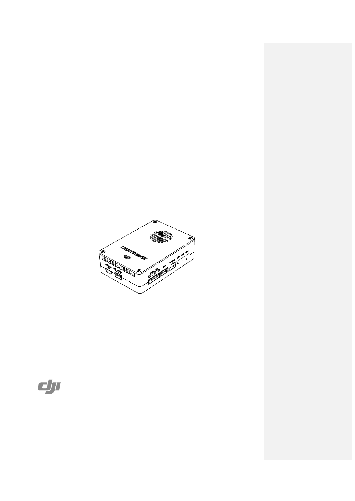
A complete Lightbridge 2 comprises of an air system an d a Groun d S ystem. I t i s a
high definition video transmitter, and sup port s Ground System using the 2.4GHz
frequency band. As it is small, power efficient and highly sensitive, the Lightbridge 2
can be used for many activities. The air system must be attached to the aircraft and
th e Ground System must be connected to a monitor to display the video and flight
contro ller info rmat ion , you can also con trol your airc r aft an d gimbal with th e Ground
System.
When the Lightbridge 2 transmits the video and flight cont ro ller info r mation, the air
system is the transmitter while the ground is the receiver. The air system pulls video
from the camera and flight controller information then modulates it and transmits to
th e Ground System. Th e Ground System th en receives the information, demodulates
it and sends it to a monitor or mobile device. The DJI GO app, available for mobile
devices is required for an ideal viewing experience.
Page 3

When the Lightbridge 2 transmits the Groun d S ystem signal, the Ground System
works as a transmitter while the air system works as a receiver. The Ground System
sup port s Du al Ground System mode. In Du al Con tro ll ers mo d e, th e “ Ma st er ”
Ground System operator controls the orientation of the aircraft, while th e “Slave”
Ground System contro ls the movement of the gimbal and camera operation. A D JI
flight control system with DBUS port is required as the built in receiver only supports
th e DJI DBUS protocol. The G roun d System includes Remote Controller module, th e
reserved buttons on th e Ground System can be customized set by the flight
controller’s assistant for expansion use.
Page 4
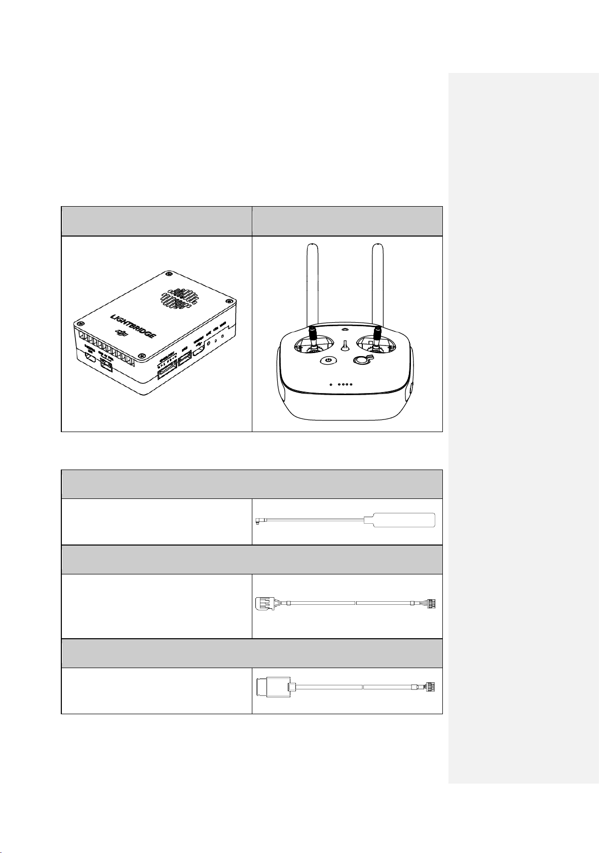
In the Box
Air system communication signals
Conn ect to o ther DJI f light contro l
Modules
Air S ys te m x 1 Ground System x 1
Air System Cables
Air System Antennas x 2
output.
DBUS Cable (A) x 1
Connect to A2/WooKong-M fligh t
control system DBUS port for
communication.
DBUS Cable (B) x 1
system DBUS port for communication.
Page 5
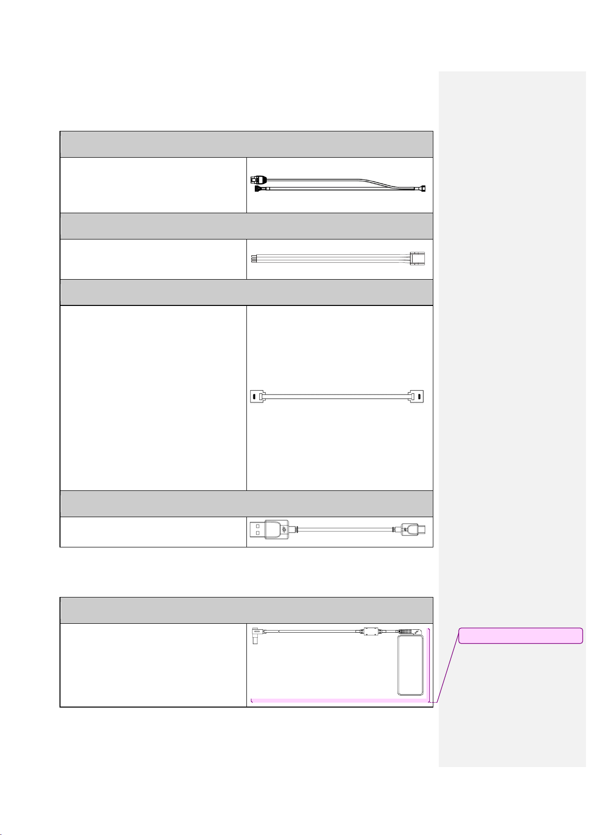
GIMBA L Cable x 1
Connect to Air system GIMBAL port, one
Comment [M1]: 电源线?
end for DJI HD gimbal, the other for
CAN port.
AV Ca ble x 1
Connect camera’s AV output to Air
system AV port.
HDMI Ca ble x 1
Connect camera’s HDMI out put to Air
system HDMI port..
USB Cable x 1
Upgrade the air system.
Ground System Cables
Charger x 1
Ch arging for the G round System.
Page 6
Mobile Device Holder x 1
HDMI Screen Holder
Mounting your mobile devic e onto the
Ground System to launch th e DJI GO
app.
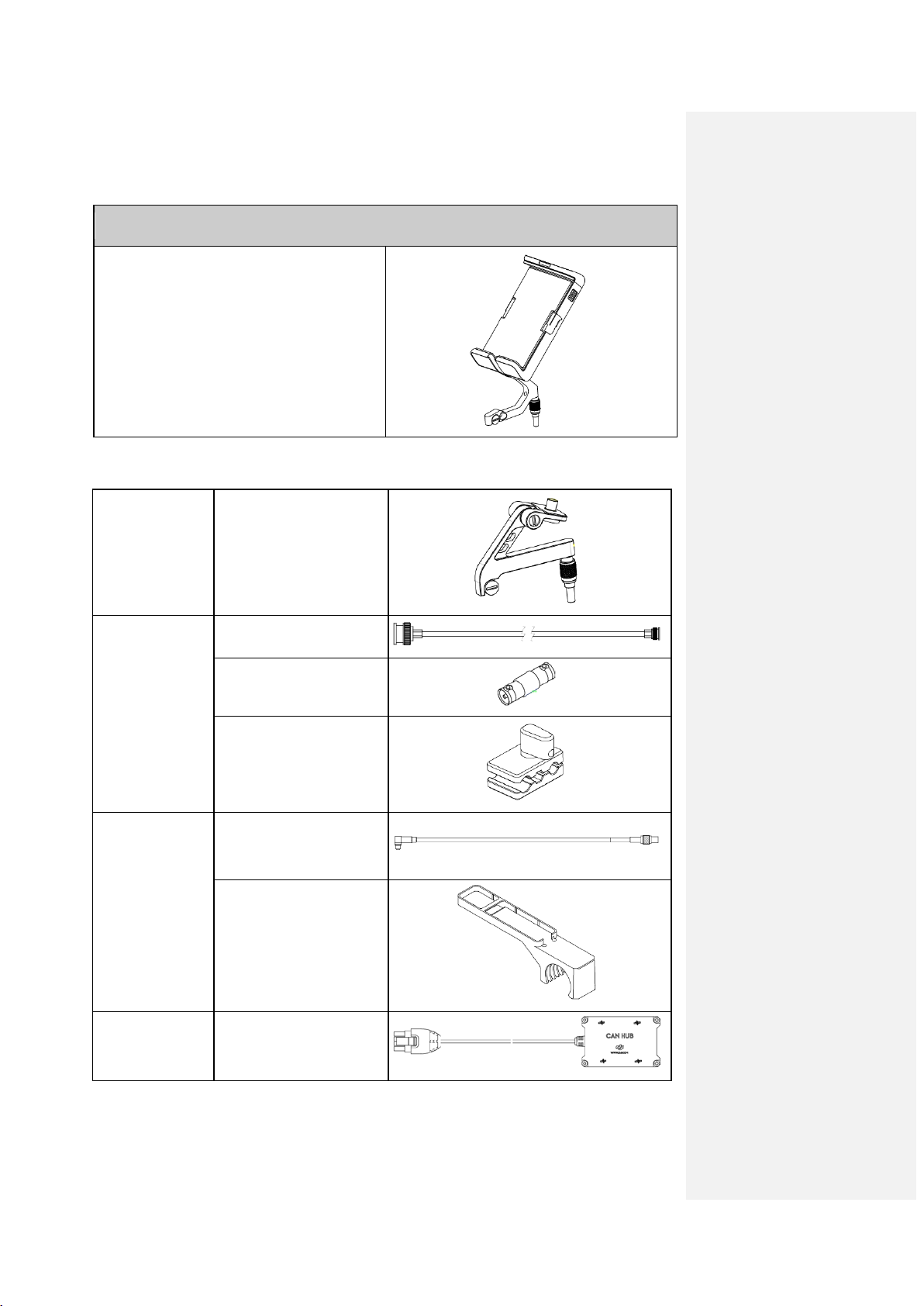
Optional Packet(Purchased Separately)
Optional
Pa cket 1
Optional
Pa cket 2
Optional
Pa cket 3
× 1
SDI Cable x 1
BNC Adapter x 1
Wire Holder x 1
Air System Antenna
Extension Cables x 2
Air System Antenna
Mounts x 2
Optional
Pa cket 4
CAN HUB x 1
Page 7

Page 8
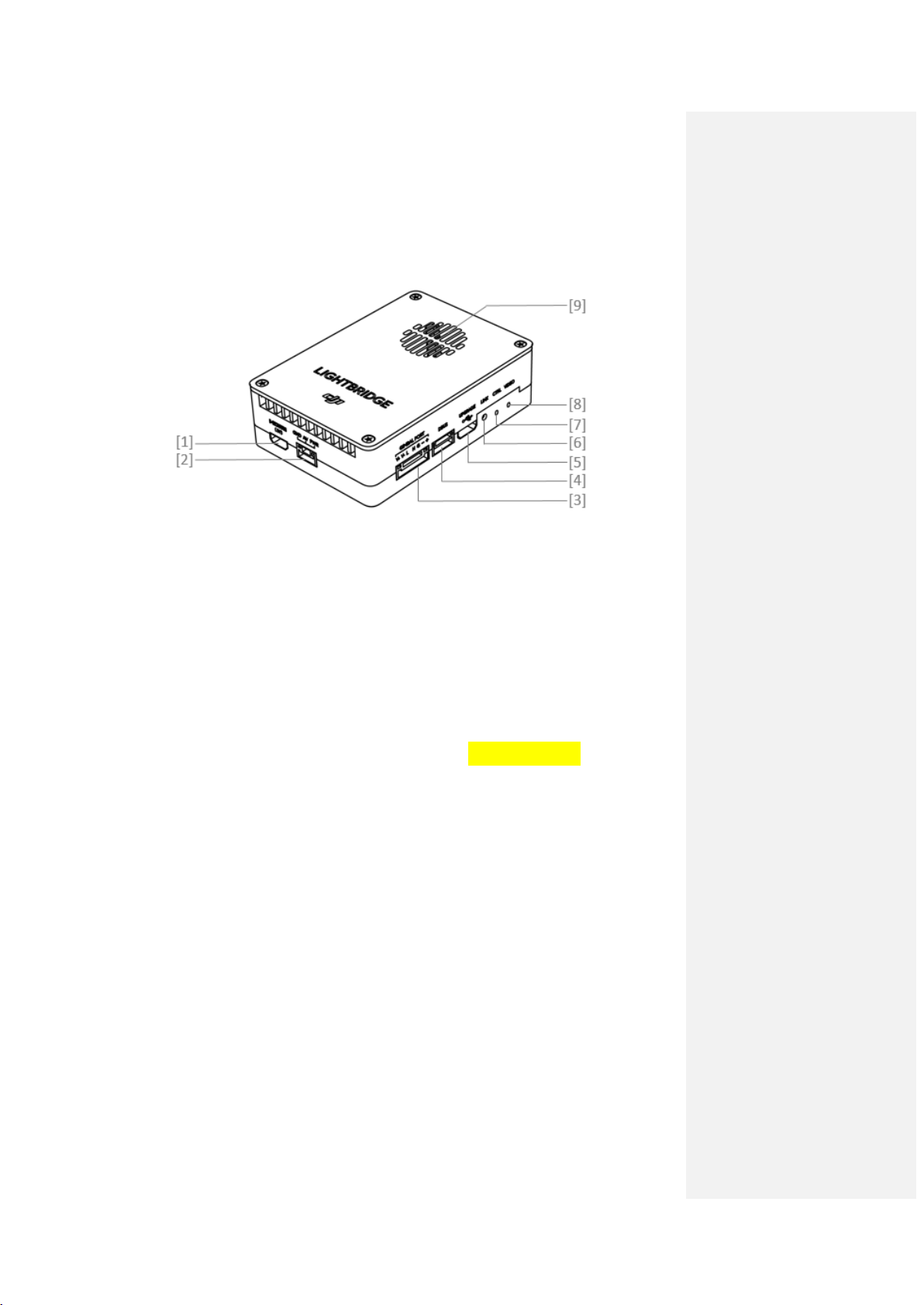
1. Introduction
1.1 Air System Diagram
[1] HDM I IN Port
Conn ect to HDMI input devic e. M aximu m input rate is 1920*1080@60fps.
[2] AV Port
Connect to AV input device.
[3] GIMBA L PORT
Conn ect th is port to the G7 po rt on a DJI HD gimbal or to other ports for the
fun ction s listed below:
a) Power su pply: (V+,V-) On-board battery (9~12V) power conn ection.
b) CAN-Bus: (L,H) Access to the flight controller information. For DJI HD gimbal
users, connect to th e CAN-Bu s port (for DJI A2/WooKong-M user, use the
CAN 2 Bus port) on th e flight controller with a seperated CAN bus cable.
c) DVSB: (G-,+ ) DVSB vid eo input f ro m DJI HD gimbal.
[4] DBUS Port
Conn ect bu ilt in receiver in terf ac e to D JI f ligh t cont rol system DBUS port, usu ally
located on the main controller labled X2 . No other receiver requried when DBUS
is used.
[5] UPGRADE Port
Connect to PC to upgrade firmware of the air system using Lightbridge 2
Assistant.
[6] LINK Buttom
Pr ess to lin k air sy st em with Ground System.
[7] CONTRO L Indi ca tor
Indicate the communtation status of the air and Ground Systems.
Page 9
Link bu tton h as been pressed. Air
system is attempting to link with
AV/HDMI signal detected and
AV/HDMI signal detected.
or not
Ind ica to r Description Instruction
Linkin g in progress.
Ground System.
Signal detected but not linked. Link requ ir ed.
Successful link. No rmal.
Power on Ground System. Ch ec k
No detected signal.
distance between ground and air
systems.
[8] VIDEO Indicator
Indicate video source transmission status.
Ind ica to r Description Instruction
functioning no r mally.
No rmal.
Air system or Ground System
Transmission f ailed .
power cycle required.
No video source detected
supported by Lightbridge 2.
Check camera and conn ection.
[9] Ve ntilation inlet
Do not obstruct ventilation fan outlet to ensure maximum cooling efficiency.
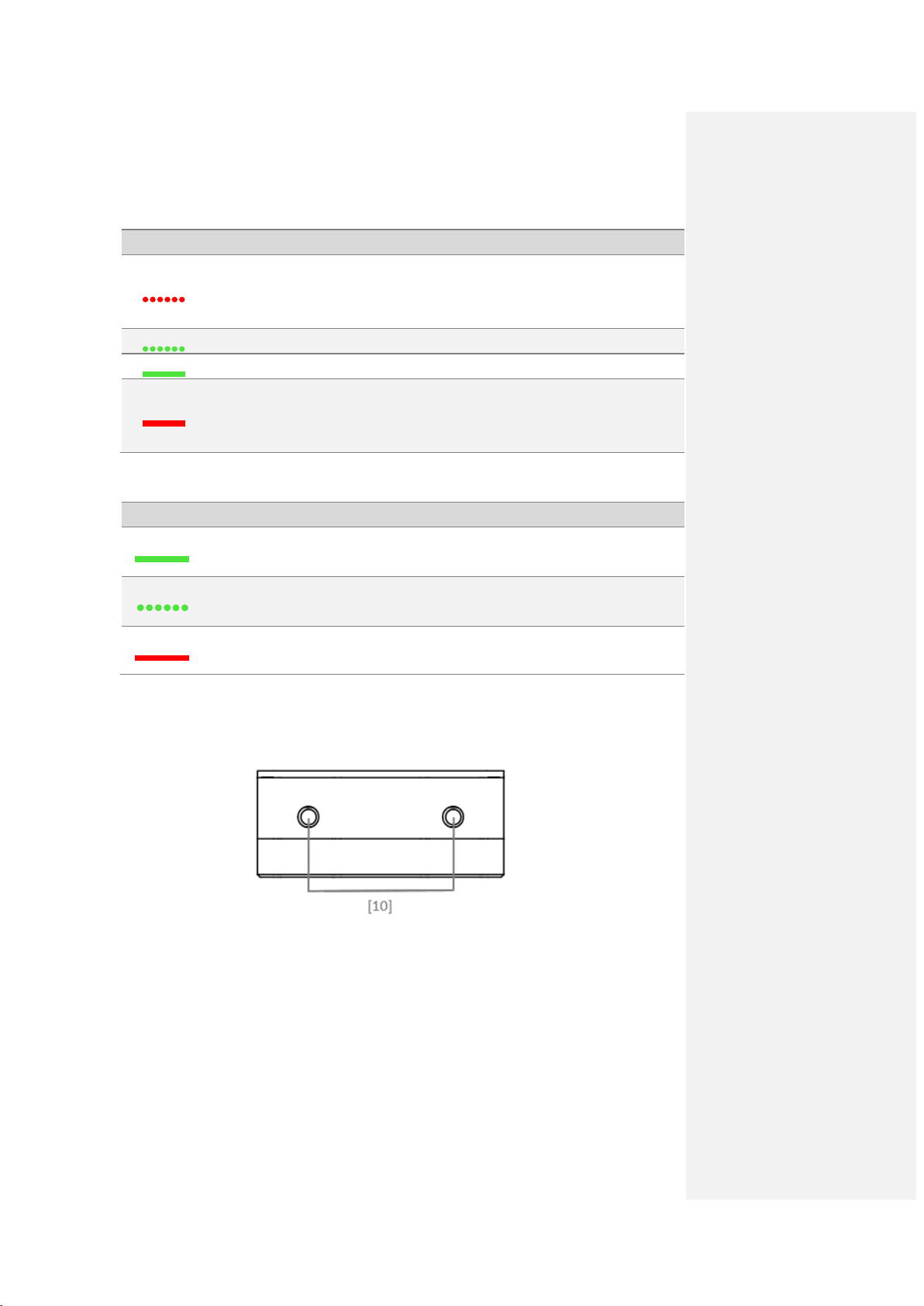
[10] Antenna Port
Page 10

1.2 Ground System Diagram
[1] Antenna s
Relays airc raft contro l an d video sign al .
[2] Mobile Device Holder Port
Mounting place for the mobile device holder.
[3] Control Sti ck
Controls th e aircr af t mo vemen t.
[4] Return Home (RTH) Button
Press and hold the button to initiate Return to Home (RTH).
[5] Transformation Switch
Customizable button in flight controller assistant.
[6] Battery Level LEDs
Displays the current battery level.
[7] Sta tus LED
Indicates the connection status of the air and Ground System.
Sta t u s LED Alarm Gro und S ystem Sta tu s
The Ground System is set as Mas t er
but is not connected to the aircraft.
The Ground System is set as Mas t er
and connected to the aircraft.
The Ground System is set as Slave but
is not conn ected to the aircraft.
The Ground System i s s et as S lav e and
Page 11

connected to the aircraft.
Home command to the
Ground System err o r.
[8] Power Button
Used to power on or power off the Groun d System.
[9] RTH LED
Circular LED around th e RTH button displays RTH status.
RTH LED Sound Ai rcra ft Sta tus
Return-to-Home procedure is activated.
S end in g R etu rn-to-
aircraft.
Return-to-Home is in progress.
[10] Camera Settings Dial
Customizable button in flight controller assistant.
[11] Playback Button
Customizable button in flight controller assistant.
[12] Shu tte r B utton
Customizable button in flight controller assistant.
[13] Flight Mode Switch
Customizable switch in flight controller assistant to set manual, attitude or GPS
mode.
Page 12

[14] Video Recording Button
Customizable button in flight controller assistant.
[15] Gimbal Dial
Customizable dial in flight controller assistant
[16] Re se rv e d Expa nsio n Po r t
Reserved port.
[17] SDI Port
Connect a SDI display device.
[18] HDMI OUT Port
Conn ect an HD compatible monitor.
[19] USB Por t
Connect to mobile device to l aunch DJI GO app, which displays the live camera
preview and OS D info rmat ion.
[20] GPS Module
Used to p inpoint th e loc at ion of th e Ground System.
[21] Back Le ft Button
Customizable button in flight controller assistant.
[22] Power Port
Conn ect to a power source to charge the Ground System’s internal battery.
[23] Back Right B utton
Customizable button in flight controller assist ant.
Page 13

2. Installation
This chapter introduces in detail the installation of air system and Ground System
before using Lightbridge 2.
2.1 Air System Antenna Installation
The air system communicates with the Ground System via antenn as. Follow th e steps
below to install the antennas onto the air system.
1. Prepare two air system paddle antennas.
2. In sert antennas into po sitions shown below. Ensure they click into place.
3. Use foam tape to mount th e air system to the XXX or other flat surfaces.
Install antennas before powering on air system.
Point antennas downward when in use and avoid obstructions to ensure
transmission quality.
Use only DJI antennas and install them correctly. Other antennas are
incompatible.
Do not apply excessive force on the antennas otherwise it may cause
damages to the antennas.
Do not unplug the antennas unless it is absolutely necessary. Use tweezers to
clamp on the metal part of the antennas when unplugging the antennas.
For use with large aircraft. Connect th e antenna extension cable to the panel
antenna before attaching the air system.
Designed for DJI Spreading Wings aircraft. Place the panel antenna into the
antenna mount, and then place the antenna mount onto the landing gear of
th e airc r aft . Note th at th e panel antenna should be at a 90 degree angle to
the landing gear. Watch the video tutorials on the DJI website for more
Page 14

details.
2.2 Ground System Connection with Display Device
SDI, HDMI and USB ports output video. Selec t on e output base on your choic e of
device.
Conn ect monitor with SDI support to SDI port, and mount the SDI screen holder
onto the Groun d System.
Conn ect monitor with HDMI support to HDMI Out port on Ground System for
video.
Connect your mobile device to the Ground System with a USB cable, and mount
your mobile device safely with a mobile device holder. Use D JI GO App for video
and flight controller information.
The below example uses th e USB port connection, prepare a slotted screwdriver.
Mounting the Mobile Device Holder:
1. Unfold the Mobile Device Holder
2. Plug the Mobile Device Holder into the Ground System and tighten the screw lock.
3. Li ne up the hole on the Mobil e Devic e Hol der with t he metal loop on the Ground System.
Insert and tighten the screw.
1E A. Remove the screw using the slotted screwdriver A○2E A.
○
Page 15

Tilt the Mobile Device Holder to the desired position and then adjust the antenna
as shown. Follow the instructions below to connect your mobile device to the
Gro und S ystem:
1. Press the button on the side of the Mobile Device Holder to release the clamp.
2. Place your mobile device inside the clamp and adjust it to secure your mobile
device.
3. C onnect your mobile device to th e Ground System via a USB cable.
Do not attach SDI and HDMI devices to the Ground System simultaneously.
2.3 Connection Scenario
Lightbridge 2 offers several solutions to connect th e gimbal to the flight controller.
This section provides information abou t th e most common ly seen solutions and their
connection diagram. Follow the connection described in the solutions that best suits
your requirements.
Page 16

2.3.1 Air Syste m
DJI HD Gimbal + DJI Flight Controller
When using with DJI HD gimbal, you can select either single or dual video source. By
single video source mode, it means the air system relays either the gimbal camera
video or the FPV camera video signal to the Ground System. These two video sources
ar e mu tu ally exclusive under single video source mode. On the other hand, the air
system simultaneously relays gimbal camera and FPV camera video signal to the
Ground System. Note that user should manually select
“HD g imb al ” in vi d eo
output source when they are conn ectin g DJI HD g imb al to th e air sy st em.
The connection steps are as follows:
1. Connect Gimbal Port on the air system with supplied Gimbal cable,then connect
it to G7 port on DJI HD gimbal and
CAN 2 Bus port on the flight controller.
2. Connect HDMI /AV port on the air system to the FPV camera.
3. Conn ect DBUS port on air system to DBUS po rt (X2 port) on flight controller with
DBUS c ab le.
4. Refer to gimbal and flight controller manuals to complete connection.
The connection figure below take DJI HD gimbal and A2 fight controller as example:
FPV c am er a i s n ot needed in single video source mode.
Page 17

2.3.2 Ground System
Dual Ground Systems Mode
More than one Ground System can connect to the same aircraft in Dual Ground
System mod e. In Dual Controllers mode, the Master G roun d S ystem c ont rol s th e
movement of the aircraft, while the Slave Ground System controls the movement of
the gimbal and camera. When multiple Slave Groun d Systems (max of 3 ) are connect
to th e ai rc raft, only the first connected Slave Ground Syst em is able to control the
gimbal, the remain ing slave Ground System can view th e live feed video f ro m th e
aircraft, but th ey cannot control th e gimbal.
Page 18

Use th e gimb al dial on th e Ground System to control the pitch movement of th e
camera in the single Ground System mode, however, you cannot pan the
camera.
Page 19

3. Ground System
The Lightbridge 2 G round System c ontain s th e remote controller, which i ntegrat es
video downlink and aircraft control. The Ground System o p er ates at 2.4 GHz with
max imu m tr ansmission distance of 2km. The device featu res a nu mb er of st andard
and customizable buttons that allow users to quickly access certain aircraft functions,
such as taking and reviewing photos/videos, as well as controlling the gimbal motion.
It is powered by a 2S rechargeable battery.
Compliance Version: The Groun d System is compliant with both C E and FCC
regulations.
Operating Mode: Control can be set to Mode 1, Mode 2.
Mode 1: The right stick serves as the throttle.
Mode 2: The left stick serves as the throttle.
D o not operate more than 3 aircrafts within in th e same area (size equivalent to
a soccer field) to prevent transmission interference.
3.1 Ground System Operations
3.3.1 Powering On and Off the Ground System
The Lightbridge 2 Ground Syst em is powered by a 2S rechargeable battery with a
capacity of 6000mAh. The battery level is indicated by the Battery Level LEDs on the
front panel. Follow th e steps below to power on/off you r Ground System:
1. When powered off, press the Power Button once and the Batter y Level LEDs will
display th e cu rrent battery level.
2. Press and hold t to power on the Groun d System.
3. The Ground System will beep when it powers on. The Status LED will blink green
(slave Ground System blin ks so lid purple) r apidly, indicatin g that the Ground
System is linking to the aircraft, then turn solid green when linking is completed.
4. Press twice and hold the power button to power off the Ground System.
Page 20

3.3.2 Charging Ground System
Charge the Ground System vi a the provided ch arger.
3.3.3 Controlling Aircraft
This section explains how to use the various features of the Ground System. Mode 2
(throttle stick on the left) is set by def ault.
St ic k Neut r al/ mid point: Con t rol st ic ks of th e Ground System are placed at the
central po sit ion .
Move the Stick: The control stick is pushed away from the central position.
Re mote
Controller
(Mode 2)
Aircra ft
( ind i ca te s no se direc tion ) Remarks
Page 21

Moving the Left Stick up/down
the aircraft’s
Use this stick to take off when
the heading of the
rotate the
right to rotate the aircraft
Push the Right Stick further for
changes
elevation. Push it up to as cen d
and down to descend.
th e motors are sp inn in g at idle
speed. The aircraft will h over in
place if the Left Stick is released.
Movin g th e Left Stick lef t/r ight
changes
aircraft. Push it left to
aircraft counter clock-wis e, and
clockwise.
Movin g th e Righ t Stic k up/ down
changes the aircraft’s for ward
an d b ac kwar d pitch. Pu sh it up
to f ly fo r w ard s an d down to f ly
backwards.
Push the Right St ick fu rth er for
a larger pitch ang le (max 35˚)
and faster flight.
Movin g th e R ight Stic k left/ right
changes the aircraft’s left and
right pitch. Pu sh it left to fly left
and right to f ly right.
a larger pitch ang le (max 35˚)
and faster flight.
Always push the control sticks gently to prevent sudden and unexpected
movement of th e aircr aft.
3.3.4 Flight Mode Switch
Page 22

Toggle the switch to select the desired flight
mode. You may choose between ; P mode, F
mod e an d A mode.
Fig ure Flight Mode
P mode (Positioning): P mode works best when GPS signal is strong.
A mode (Attitude): The GPS is not used for holding position. The aircraft only uses its
baromet er to maintain altitu de. If it is st ill r eceiving a GPS signal, th e airc raft can
automatically Return-To-Home if th e Ground System signal is lost and if th e Ho me
Point has been recorded successfully.
F mo d e (M anu al): Manu al mo d e.
F mode
A mode
P mod e
3.3.5 RTH Button
Press and hold this button to start the Return to Home (RTH) procedure. The LED
around th e RTH Button will blink white to indicate the aircraft is entering RTH mode.
The a i rc r aft wi ll th en retu rn to th e la s t rec ord ed Home Point.
The RTH procedu re can’t be canceled since it started.
Page 23

3.3.6 Optimal Transmission Range
The signal transmission between Air and Groun d S yst em perform best within the
range that displayed in the picture shown below:
Ensure the aircraft is flying within the optimal transmission range. Adjust the distance
and position between th e operator and the air system to ach ieve optimal
transmission performance.
3.2 Setting up Dual Ground Systems Mo de
The Dual Ground Systems mo d e is disab led by default. User s mu st enable this featur e
on the Master Ground System through the DJI GO app. Follow th e steps below for
setup:
Ma ste r Gro und System:
1. Connect the Ground System to your mobile device and launch the DJI GO app.
2. Go to the Camera V iew, and tap
to enter the Ground System settings
window.
3. Select Master in the Set RC Status section to set the Groun d System as the Master
Ground System.
Page 24

4. Enter the connection password for the Slave Groun d System.
Slave Ground S ystem:
1. Select Slave in th e Set RC Status section to set th e G round System as the Slave
Ground System.
Page 25

2. Tap S earch for Master Controller to register th e Master Groun d S yst em.
3. S elec t th e n ame of th e Ground System from th e M aster RC List and input the
connection password to conn ect to the desired Master Groun d Syst em.
Th e Ground System cannot lin k to the aircraft or cont rol aircraft movement if it
is set to Slave. Set the Groun d S yst em as M ast er in the DJI GO app if you want
to link the Ground System to th e aircraft.
3.3 Linking the Ground System
The Ground System is linked to your air system by default. Linking is only required
when a new Ground System is used for the first time. Follow these steps to link a new
Ground System:
1. Power on the G round System and connect it to your mobile device.
2. Launch the DJI GO app. G o to th e DJI GO app > Camera View > > RC
Control Settings >Linking RC.
Page 26

3. The G round System Status LED will blink blue and emit a ‘beep’ sound to
indicate that th e Ground System is ready to be linked.
4. Pres s th e LINK Button on th e air system to beg in lin king. Th e Ground System
Status LED will glow solid green if linking is successful.
Th e Ground System cannot link to th e aircraft or control airc raft movement if
it is set to Slave. Set the Ground System as Master in the DJI GO app if you
want to link the Ground System to the aircraft.
The Groun d Syst em will disconn ect from th e l inked aircraft if ano th er Ground
System attempts to link to the same aircraft.
Page 27

3.4 Ground System Compliance
The Ground System is compliant with CE and FCC standards.
Page 28

4. Appendix
Performance Parameters
Max Transmission Distance
Working Frequency
2.4GHz ISM
Air System Antennas Gain
2dBi@2450MHz
Ground System Antennas Gain
3.5dBi@2450MHz
Physical Parameters
Operating Temperature
-10~40℃
Air system: 68mm (L)X48mm (W )X21 mm(H)
Air system: 70g
Hardware Functions Supported
Air System Operating Amperage
650mA(@12V)
Ground System Battery
7.4V 6000mAH
Ground System Operat in g
DJI HD Gimbal
Z15-GH4, Z15-5D3, Z15-A7
Fl ight Con trol S yste m
A2, WooKong-M
4.1 Spe cifi cati on
(ou tdoors and unobstructed)
EIRP 100mW
Dimension (no antennas)
Gross Weight (no antennas)
Antenna Connector MMCX Male (air system)
Air System Operating Voltage 9~12V
2Km(Stadia, no interference)
Ground System:182mm (L) X 167mm(W ) X
104mm(H)
Ground System: 810g
Amperag e
4.2 Supported DJI Products
Please upgrade to the latest firmware version.
4.3 Supported Video Sources
900mA
Page 29

Mode
Format
AV
PAL2 5,N TS C30
HDMI
720p50,72 0p60,1080i50,1080i60,1080p25,1080p30,
Mode
Format
HDMI
720p50,72 0p60,1080i50,1080i60,1080p50,1080p60
720p50,72 0p60,1080i50,1080i60,1080p50,1080p60
1080p50,1080p60
4.4 Supported Vide o Outputs
SDI
Page 30

Chang es or mo d ification s not expressly appro v ed by the p art y responsible for
compliance could void the u ser’s authority to operate the equipment.
This equipment has been tested and found to comply with the limits for a Class B
digital device, pursuant to Part 15 of the FCC Rules. These limits are designed to
provide reasonable protection against harmful interference in a residential
installation. This equipment generates, uses and can radiate radio frequency en erg y
and, if not installed and used in accordance with the instructions, may cause harmful
interference to radio communications. However, there is no guarantee that
interference will not occur in a particular installation.
If this equipment does cause harmful interference to radio or television reception,
which can be determined by turning the equipment off and on, the user is
en cou r ag ed t o try to co r r ec t th e in t erf er en ce b y on e o r mo re of th e fo llo w in g
measures:
-- Reorient or relocate the receiving antenn a.
-- Increase the separation between the equipment and receiver.
-- Connect th e equipment into an outlet on a circu it different from that to which the
receiver is connected.
-- Consult the dealer or an experienced radio/ TV technician for help.
This device complies with Industry Canada license-exempt RSS standard(s). Operation
is subject to the following two conditions: (1 ) this device may not cause interference,
and (2) this device must accept any interference, including interference that may
cause undesired operation of th e device.
Le pr és en t a pp a r ei l es t con form e aux C N R d'I ndu st r ie C an ad a app lic abl es aux
appareils radio
exempts de licence. L'exploitation est autorisée aux deux conditions suivantes : (1)
l'appareil ne
doit pas produire de brouillage, et (2) l'utilisateur de l'appareil doit accepter tout
brouillage
Page 31

radioélectrique subi, même si le brouillage est susceptible d'en compromettre le
fonctionnement.
 Loading...