

Page 1

AGRAS MG-1
User Manual
V1.0 2016.02
Page 2

AGRAS MG-1 User Manual
Contents
Installation ................................................................................................................................................................ 3
Mounting the Landing Gear .............................................................................................................................. 3
Mounting the Liquid Tank.................................................................................................................................. 4
Unfolding the Frame Arms ................................................................................................................................ 5
Mounting the Sprinklers .................................................................................................................................... 5
Mounting the Radar-Assisting Altitude Stabilization System ............................................................................. 7
Connecting the Batteries ................................................................................................................................... 7
Remote Controller..................................................................................................................................................... 9
Profile ................................................................................................................................................................ 9
Prepare the Remote Controller ......................................................................................................................... 9
Remote Controller Diagram............................................................................................................................. 10
Using the Remote Controller ........................................................................................................................... 10
Turning the Remote Controller On and Off...................................................................................................... 10
Remote Controller LED .................................................................................................................................... 14
Operation Status Display Panel ....................................................................................................................... 15
Aircraft .................................................................................................................................................................... 18
Profile .............................................................................................................................................................. 18
Operation Mode .............................................................................................................................................. 18
Radar Assisted Altitude Stabilization System ................................................................................................... 22
No Liquid Warning........................................................................................................................................... 23
Return-to-Home (RTH) .................................................................................................................................... 24
Low Battery Level Warning .............................................................................................................................. 25
Flight ....................................................................................................................................................................... 26
Starting and Stopping the Motors ................................................................................................................... 26
Appendix ................................................................................................................................................................. 27
Specifications .................................................................................................................................................. 27
Aircraft Status Indicator Description................................................................................................................ 28
© 2016 DJI. All Rights Reserved. 2
Page 3

AGRAS MG-1 User Manual
The structures of the two landing gear legs are different. The one with a compass cable should be
mounted to the right side of the aircraft (with its tail facing you).
Aircraft’s Tail
Compass Cable
(For the right landing gear leg only)
Compass Port
Compass Cable
Hose Bracket
Installation
Mounting the Landing Gear
1. Mounting the right landing gear leg
There is a compass cable in the landing gear leg. Connect the compass cable before mounting the landing gear leg.
Connect the compass cable to the compass port in the landing gear mount on the right side of the center frame.
Use tools such as tweezers if needed.
Mount the landing gear leg to the center frame. DO NOT damage the compass cable.
Insert and tighten M3x10 screws.
2. Follow the step 2 and 3 above to mount the left landing gear leg.
© 2016 DJI. All Rights Reserved. 3
Page 4

AGRAS MG-1 User Manual
Battery Mounting Position
Battery Lock
Mounting Holes
Liquid Pump
Fittings
Motor Cable
Mounting the Liquid Tank
1. Insert the four liquid tank plugs into the mounting holes on the liquid tank.
2. Hold up the liuid tak to the loe positio of the ete fae ith the liuid pup faig the aiaft’s tail.
3. Align the mounting holes on the liquid tank and landing gear. Tighten the four M5x1 8 screws on the two sides.
4. Align the fin on the motor cable connector and the slot on the motor port. Then plug the motor cable.
© 2016 DJI. All Rights Reserved. 4
Page 5

AGRAS MG-1 User Manual
Motor Port
Motor Cable
Unfolding the Frame Arms
1. Unfold the frame arms totally. Tighten each sleeve at the eight junctions.
2. Double check the positions of the frame arms. Frame arms M1 and M2 form the front of the aircraft, while frame
arms M5 and M6 form its rear. Seen from the top, motors on frame arms M1, M3 and M5 should rotate counter
clockwise, while motors on frame arms M2, M4 and M6 should rotate clockwise.
Mounting the Sprinklers
1. Thee ae spikle outig positios o the otto of the fou otos o the aiaft’s left and right side
(motors on frame arms M3, M4, M7 and M8). Tighten the two M3x6 screws to mount the sprinklers.
© 2016 DJI. All Rights Reserved. 5
Page 6

AGRAS MG-1 User Manual
2. Prepare hose clamps A. Tools such as pincers may be required. Follow the instructions below to connect the other
end of the hose to the liquid pump.
Pull the hose through the hose clamp A and then connect it to the fitting of the liquid pump.
Open the hose clamp A by tools such as pincers. Move it to the fitting and release the hose clamp A to grip the
hose.
3. Prepare hose clamps B and M3x6 screws to fix the hoses to the arms and landing gear.
Open the hose clamp B to an appropriate angle to hold the hose. DO NOT damage the clamps.
Tighten one M3x6 screw to the hose bracket on the landing gear.
Tighten one M3x6 screw to the mounting hole on the bottom of the frame arm junction.
© 2016 DJI. All Rights Reserved. 6
Page 7
AGRAS MG-1 User Manual
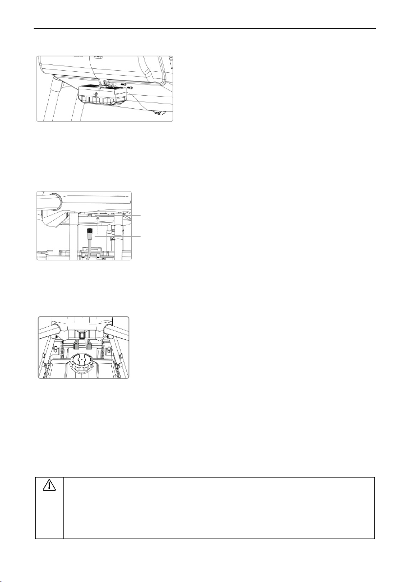
Mounting the Radar-Assisting Altitude Stabilization System
1. Arrange the side with a DJI logo outwards.
2. Align the mounting holes on the liquid tank and altitude stabilization system. Then tighten two M3x8 screws.
3. Align the slot inside the radar cable connector and fin of the radar port on the center frame. Plug the cable and
then rotate the upper part of the cable to the left to insert it into the slot on the cable port.
Radar Port
Radar Cable
Connecting the Batteries
There are two XT90 ports on the aircraft. The allowable voltage is 22.2 V for every XT90 port. Connect two 6S
batteries in series to get a maximum power supply of 50.4 V.
Battery Use Requirement:
1. Be sure to use two 6S LiPo batteries of the same model. 6S Li Po batteries of 12000 mAh capacity and 10C
continuous discharging rate are recommended.
2. Ensure that the voltage of the two batteries used is the same.
3. The two batteries must be used together all the time. Replace the two batteries together for safe use, if one of
them is damaged.
Batteries are required but not included with the MG-1.
The batteries for the MG-1 are of high voltage and energy. Use them in accordance with their
instructions and make safety your top priority. DJI assumes no liability for damage(s) or injuries
© 2016 DJI. All Rights Reserved. 7
incurred from using batteries.
Page 8

AGRAS MG-1 User Manual
Place your batteries to the battery position on the liquid tank. Pull the Velcro through the battery lock and bind the
batteries as shown below.
© 2016 DJI. All Rights Reserved. 8
Page 9

AGRAS MG-1 User Manual
Compliance Version: The remote controller is compliant with both CE and FCC regulations.
Operating Mode: Control can be set to Mode 1 or Mode 2, or to a custom mode.
Mode 1: The right stick serves as the throttle.
Mode 2: The left stick serves as the throttle.
To prevent transmission interference, do not operate more than three aircrafts in the same area.
Remote Controller
Profile
The aircraft remote control system operates at 2.4 GHz and the maximum transmission distance is 5 km. The remote
controller features a number of spray system control functions to help complete operation mission. Users can switch
between different operation modes via the remote controller.
Prepare the Remote Controller
Mounting the Operation Status Display Panel
1. Unfold the Operation Status Display Panel. Remove the screw using the slotted screwdriver c oming with the
MG-1.
2. Plug the panel into the remote controller and tighten the screw lock.
3. Line up the hole on the panel with the metal loop on the remote controller. Insert and tighten the screw.
Adjusting the Antenna and Connecting the Panel
1. Tilt the Panel to the desired position. Adjust the antenna as shown.
2. Plug the cable of the panel into the CAN port on back of the remote controller.
© 2016 DJI. All Rights Reserved. 9
Page 10
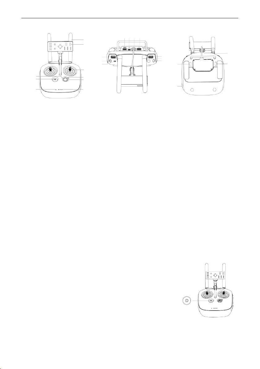
Remote Controller Diagram
[1] Antennas
Relays the aircraft control signals.
[2] Operation Status Display Panel
Displays the operation status.
[3] Control Stick
Controls the aircraft movement.
[4] Operation Mode Switch
Used to s witch between Smart, Ass isted and
Manual Operation Mode.
[5] Return-to-Home (RTH) Button
Press and hold this button to initiate Return-toHome (RTH).
[6] Battery Level LEDs
Display the current battery level.
[7] Status LED
Indicates whether the remote controller is linked
to the aircraft.
[8] Power Button
Used to power on/off the remote controller.
[9] RTH LED
Circular LED around the RTH button which displays
the RTH status.
[10] Flying Speed Dial
In Smart Operation Mode, turn and press the dial
to adjust the flying speed.
[11] Button A
Records the A Point of the operation route.
[12] Button B
Records the B Point of the operation route.
[13] Flight Mode Switch
Used to switch between G-Mode (GPS), A-Mode (Attitude) and MMode (Manual).
[14] Spray Button
In MO-Mode, press to start / stop spraying.
[15] Spray Speed Dial
In MO-Mode, turn the dial to adjust the spray speed.
[16] Mini HDMI Port
Reserved.
[17] Micro USB Port
Reserved.
[18] CAN Port
Connects to the operation status display panel.
[19] USB Port
To update the firmware.
[20] GPS Module
Used to pinpoint the location of the remote controller.
[21] Back Left Button C1
Press to choose left as the direction of the operation route in SOMode. In AO-Mode, press to fly the aircraft left by one operation
width.
[22] Power Port
Coets to a poe soue to hage the eote otolle’s
internal battery.
[23] Back Right Button C2
Press to choose right as the direction of the operation route in
Smart Operation Mode. In AO-Mode, press to fly the aircraft right
by one operation width.
[2]
[10]
[3]
[4]
[5]
[6]
[7]
[8]
[9]
[11]
[12]
[13]
[14]
[15]
[16]
[17]
[18]
[19]
[21]
[22]
[23]
[20]
[1]
AGRAS MG-1 User Manual
Using the Remote Controller
Turning the Remote Controller On and Off
The remote controller is powered by a 2S rechargeable battery that has a capacity
of 6000 mAh. The battery level is indicated via the Battery Level LEDs on the front
panel. Follow the steps below to turn on your remote controller:
1. When the remote controller is turned off, press the Power Button once. The
Battery Level LEDs will display the current battery level.
2. Press the Power Button once. Then press again and hold the Power Button to turn on the remote controller.
3. The remote controller will beep when it is turned on. The Status LED will rapidly blink green, indicating that the
© 2016 DJI. All Rights Reserved. 10
Page 11

AGRAS MG-1 User Manual
The final movement of the dial before you press the dial will be used to set the flying speed.
[1]
[2]
[5]
[4]
[3]
[6]
[7]
Charger
Power Outlet
remote controller is linking to the aircraft. The Status LEDs will glow solid green when linking is complete.
4. Repeat Step 2 to turn off the remote controller.
Charging the Remote Controller
Charge the remote controller using the included charger. Refer to the figure below for more details.
Controlling the Spray System
Adjust the flying speed, record Point A and B, start or stop spraying, adjust spray speed, choose the route direction
via the Flying Speed Dial, Button A / B, Spray Button, Spray Speed Dial, Button C1 / C2.
[1] Flying Speed Dial
In Smart Operation Mode, turn and press the dial to adjust the flying speed. You can set four speed gears in the A2-
AG Assistant. The four speed gears are set to 3, 4, 5, 6 m/s by default, and the initial flying speed is the speed of the
first gear. Move the dial to the left and press the dial to change to the previous speed. Move the dial to the right
and press the dial to change to the next speed. The operation status display panel will indicate the current speed
gear.
[2] Button A
Press the button to record Point A of the Smart Operation route.
[3] Button B
Press the button to record Point B after Point A recorded.
[4] Spray Button
In Manual Operation Mode, press the button to start or stop spraying.
[5] Spray Speed Dial
In Manual Operation Mode, turn the dial to adjust the spray speed. Move the dial to the left to reduce the spray
speed. Move the dial to the right to increase the spray speed. The speed range is 40% - 100%*. The Operation Status
Display Panel will indicate the current spray speed. Refer to Operation Status Display Panel for detail. The spray
© 2016 DJI. All Rights Reserved. 11
Page 12

AGRAS MG-1 User Manual
Stick Neutral/Mid-Point: Control sticks are placed at the central position.
Moving the Control Stick: The control stick is pushed away from the center position.
Remote Controller
(Mode 2)
Aircraft
( Indicates Nose Direction)
Remarks
Vertical m ovement of the left stick controls
the aiaft’s eleatio. Push up to ased and
press down to descend. Use the left stick to
take off when the motors are spinning at idle
speed. The aircraft will hover in place if the
stick is in the central position.
The more the stick is pushed away from the
central position, the faster the aircraft will
change elevation.
Horizontal movement of the left stick controls
the aircraft's heading. Move left to rotate the
aircraft anticlockwise and move right to rotate
the aircraft clockwise. The aircraft will hover
in place if the stick is in the central position.
The more the stick is pushed away from the
central position, the faster the aircraft will
rotate.
speed is the value for the last Manual Operation Mode when you restart the remote controller or the aircraft is in
Smart Operation Mode.
* We use a percentage for the spray speed due to the various thickness of liquid. The percentage is the ratio of the current speed to the maximum speed. For
water, 100% means 1.25 L/min with four TXVK-04 nozzles and 1.7 L/min with four XR11001 nozzles.
[6] Back Left Button C1
Press the button to choose the left direction for the Smart Operation route after Point A and B recorded.
[7] Back Right Button C2
Press the button to choose the right direction for the Smart Operation route after Point A and B recorded.
In Smart Operation Mode, when the aircraft is hovering at the key point, press Button C1 and C2 together and then
the aircraft will fly to the next key point and hover. Press and hold Button C1 and C2 together for more than 2
seconds until there is a beep emitted from the remote controller, and the aircraft will enter or quit from Continuous
Smart Operation Status. Refer to Smart Operation Mode for more details.
Controlling the Aircraft
The Remote Control is set to Mode 2 by default.
© 2016 DJI. All Rights Reserved. 12
Page 13

Vertical movement of the right stick controls
the aiaft’s pith. Push up to fl foads
and press down to fly backwards. The aircraft
will hover in place if the stick is in the central
position.
Move the stick further for a larger pitch angle
and faster flight.
Horizontal movement of the right stick
otols the aiaft’s oll. Moe the stik left
to fly left and right to fly right.
The aircraft will hover in place if the stick is in
the central position.
Move the stick further for a larger roll angle
and faster flight.
The description above is only for the G-Mode and A-Mode.
Figure
Flight Mode
G
G-Mode (GPS)
A
A-Mode (Attitude)
M
M-Mode (Manual)
M
A
G
Flight Modes
Toggle the Flight Mode Switch on the remote controller to one of the three
modes.
AGRAS MG-1 User Manual
G-Mode (GPS): The aircraft uses GPS for positioning. Only in G-Mode and when the GPS signal is strong, users can
start the motors.
A-Mode (Attitude): GPS is not used for positioning, a nd the aircraft only uses its barometer to maintain altitude. If
a GPS signal is present, the aircraft will still return to the last recorded Home Point if the remote controller signal is
lost.
M-Mode (Manual): Set as Manual or Attitude in the A2-AG Assistant. It is set to Attitude by default. Beginners do
NOT set it to Manual. In Manual Mode, GPS and the attitude stabilization are not used. Control the aircraft by
yourself totally.
Operation Mode Switch
Toggle the Operation Mode Switch on the remote controller to one of the three modes.
Smart Operation Mode Manual Operation Mode Assisted Operation Mode
© 2016 DJI. All Rights Reserved. 13
Page 14

AGRAS MG-1 User Manual
Status LED
Sound
Remote Controller Status
— Solid Red
The remote controller is not connected to the aircraft.
— Solid Green
The remote controller is connected to the aircraft.
Blinks Red
D-D-D......
Remote controller error.
Status LED
RTH LED
1. Smart Operation Mode: When the aircraft is in G-Mode and the GPS signal is strong, toggle the switch to this
mode and the aircraft will fly and spray liquid in a certain route after Point A and B recorded.
2. Manual Operation Mode: In Manual Operation Mode, users can control the whole movement of the aircraft and
spray liquid via the Spray Button.
3. Assisted Operation Mode: In Assisted Operation Mode, the flying speed is restricted and the aiaft’s headig is
locked. Users can control the movement of the aircraft except the heading. Press Button C1 or C2 and the aircraft
ill fl oe opeatio idth to the left o ight. It spas liuid he flig foads ad akads. It does’t spas
liquid when flying left and right.
RTH Button
Press and hold the RTH Button to bring the aircraft back to the last recorded Home Point. The
LED around the RTH Button will blink white during the RTH procedure. Users can control the
aircraft during the procedure. Regain control manually to cancel the RTH procedure. Refer to
How to Regain Control for details.
Optimal Transmission Range
The signal transmission between the aircraft and the remote controller performs best when the aircraft is within
the optimal transmission range. Open up the antennas on the rem ote controller to optimize transmission range.
Ideally, the flat surface of the antenna should be facing the aircraft. If the signal is weak, fly the aircraft closer to
you.
Optimal Transmission Range
Strong Weak
Remote Controller LED
The Status LED indicates the connection status between the remote controller and the aircraft. The RTH LED
indicates the Return-to-Home status of the aircraft. See the table below for details on these indicators.
© 2016 DJI. All Rights Reserved. 14
Page 15

AGRAS MG-1 User Manual
RTH LED
Sound
Aircraft Status
— Solid White
chime
Return-to-Home procedure is initiated.
Blinks White
D . . .
Sending Return-to-Home command to the aircraft.
Blinks White
DD .. .. ..
The aircraft is returning to the Home Point.
LED1
LED2
LED3
LED4
Spray Speed
x1 ……
40%~45%
……
45%~50%
50%~55%
x1 ……
55%~60%
……
60%~65%
65%~70%
[1]
[2]
[4]
[3]
[5]
[6]
[7]
[9]
[8]
[10]
[11]
[12]
Operation Status Display Panel
[1] Battery Level
Displays the current battery level.
[2] Point A LED
The LED is on after Point A recorded.
[3] Point B LED
The LED is on after Point B recorded.
[4] Orientation LED
In Smart Operation Mode, indicates the current flying orientation.
[5] Spray Speed
Displays the current spray speed. The range is 40% - 100%. See the table below for details. (The bottom is LED1 and
the top is LED4.)
LED is on. LED is blinking. LED is off.
© 2016 DJI. All Rights Reserved. 15
Page 16

AGRAS MG-1 User Manual
x1 ……
70%~75%
……
75%~80%
80%~85%
x1 ……
85%~90%
x2 ……
90%~95%
95%~100%
LED1
LED2
LED3
LED4
Relative Altitude
< 2 m
2 m
2.5 m
3 m
3.5 m
4 m
> 4 m
[6] Relative Altitude
Display the relative altitude between the aircraft and the crops (or the surface under the aircraft). See the table
below for details. (The bottom is LED1 and the top is LED4.)
LED is on. LED is blinking. LED is off.
[7] Flying Speed
In Smart Operation Mode, displays the current speed gear. You can set four speed gears in the A2 -AG Assistant.
Select the speed gear via the Flying Speed Dial on the remote controller. The number (1 to 4) of the LED(s) that is
(are) on indicates the current speed gear (the first to the fourth gear).
[8] Return LED
In Smart Operation Mode, if the task resumption function is initiated, the flight controller will record a br eaking
point. After breaking, the aircraft will return to the point and the Return LED will be on during the procedure.
[9] Continuous Smart Operation LED
In Smart Operation Mode, when the aircraft is hovering at the key point, press and hold Button C1 and C2 together
for more than 2 seconds until there is a beep emitted from the remote controller, and the aircraft will enter
Continuous Smart Operation Status. This LED will be on. Refer to Smart Operation Mode for more details.
[10] Spray LED
The LED is on when the aircraft is spraying liquid.
[11] Liquid Level
The LED is solid green when there is liquid in the liquid tank. The LED is blinking red when there is no liquid in the
liquid tank.
© 2016 DJI. All Rights Reserved. 16
Page 17

AGRAS MG-1 User Manual
[12] Brightness Setting Button
Press to adjust the LED brightness of the panel. The left part is to reduce the brightness and the right part is to
increase the brightness.
© 2016 DJI. All Rights Reserved. 17
Page 18

AGRAS MG-1 User Manual
The effect of the pesticides is related to the pesticide density, spray speed, flying speed, altitude above
the crops, wind direction and wind speed. Consider a ll the factors for optimal effect when using the
pesticides.
Fly the aircraft above the crops at a proper height to avoid damage to the crops.
Maintain line of sight of the aircraft at all times.
Ensure that the Flight Mode Switch is toggled to GPS Flight Mode a nd the GPS signal is strong (the
number of GPS ≥ 6). Otherwise, Smart Operation may be difficult.
It’s eoeded to pla the opeatio oute fo effiiet operation.
Aircraft
Profile
The MG-1 has Smart Operation Mode, Manual Operation Mode and Assisted Operation Mode. Switch to one of the
three modes via the Operation Mode Switch on the remote controller. In Smart Operation Mode, the aircraft will
fly in a certain route and spray liquid automatically. In the Assisted Operation Mode, the flying speed and the
aiaft’s headig ill e estited. The aiaft ill spa liuid autoatiall ad uses a otol the aiaft to
fly a certain width in the left or right direction via the buttons on the remote controller. In Manual Operation Mode,
users can control the aircraft and spray liquid via the button on the remote controller.
Operation Mode
Smart Operation Mode
In Smart Operation Mode, the aircraft will fly in a certain route and spray liquid automatically. Flight task resumption,
data protection, and altitude stabilization system are available in this mode. It is recommended to fly in Smart
Operation Mode when the spray area is large and approximately rectangular.
Operation Route
The aircraft will fly i n snakelike operation route 1 or 2 as shown below and spray liquid for the whole area after
Point A and B recorded. The description in this manual is based on the directions in the illustrator. Points like C and
D are called key point. Distances like AB and CD are called operation l ength. Distances like BC and DE are called
operation width. All the corners in the illustrator are right angles.
Operation Procedure
© 2016 DJI. All Rights Reserved. 18
Page 19

AGRAS MG-1 User Manual
If you want to update Point B after Point A and B recorded, fly the aircraft to the new Point B and record it.
If you want to update Point A after Point A and B recorded, record the new Point A and then record Point
B again.
It’s recommended to keep the direction of Point A to B parallel to the long side of the rectangular spray
area for optimal effect.
The aircraft’s ose dietio ill poit to the dietion of Point A to B at all times without change by
the flying direction.
The context below takes a right direction of Point C for example.
Instructions
Ensure that the Operation Mode Switch is toggled to Manual Operation Mode, and then follow the instructions
below:
1. Recording Point A and B
Switch to the Smart Operation Mode only after Point A and B recorded.
Recording Point A First:
Fly the aircraft to the planning Point A and hover. Press Button A on the remote controller. The Point A LED on the
Operation Status Display Panel glows solid green and the Aircraft Status Indicator flashes red for eight times indicate
that Point A is recorded successfully.
Recording Point B Secondly:
Fly the aircraft to the planning Point B and hover. Press Button B on the remote controller. The Point B LED on the
Operation Status Display Panel glows solid green and the Aircraft Status Indicator flashes green for eight times
indicate that Point A is recorded successfully.
2. Selecting the Orientation of Point C
Press Back Left Button C1 or Back Right Button C2 on the remote controller to select the orientation of Point C, C1
for left and C2 for right. The corresponding Orientation LED on the Operation Status Display Panel will be blinking
afte seletio. The oietatio of Poit C ill e ight if ou did’t pess a of the C ad C uttos.
3. Enabling Smart Operation Mode
Ensure that the Flight Mode Switch is toggled to GPS Flight Mode and the GPS signal is strong (the number of GPS
6). Then toggle the Operation Mode Switch to Smart Operation Mode. The aircraft enters Smart Operation Mode
≥
and hovers at Point B. The aiaft’s ose direction points to the direction of Point A to B automatically. The left and
right Orientation LED on the Operation Status Display Panel blinks.
4. Starting Operation
1) Press the Back Left Button C1 and Back Right Button C2 on the remote controller at the same time. The Aircraft
Status Indicator will flash blue for four times. The aircraft will fly from Point B to C and then hover at Point C. The
© 2016 DJI. All Rights Reserved. 19
Page 20

AGRAS MG-1 User Manual
Only if the aircraft is hovering at a key point, the action of pressing button C1 and C2 in Step 1) to 3)
will be available.
If the GPS signal is weak (the number of GPS < 6) in operation, the Flight Mode will switch to Attitude
Flight Mode automatically, and you can spray liquid via the Spray Button on the remote controller. If
the MG-1 regains GPS signal afterwards, it will fly to the next key point automatically.
The distance of BC is called operation width. It is set to 5 m by default. You can customize it from 3 to
10 m in the A2-AG Assistant.
You can control the left, right, forward, backward directions and the throttle of the aircraft to avoid
obstacles when in operation, but the heading of the aircraft cannot be controlled. The aircraft will fly
back to the operation route automatically and continue operation when releasing the control sticks.
Release the control sticks only after avoiding the obstacles totally. Otherwise, it may cause aircraft
collision on the way back to the operation route.
The aircraft sprays liquid automatically when flying in the forward and backward direction, but it
does’t spas liuid he flig i the left ad ight dietio.
The spray speed cannot be adjusted in Smart Operation Mode. It will be set to a value the same as it
in Manual Operation Mode. You can enter Manual Operation Mode to adjust the desired spray speed
(refer to Controlling the Spray System for details) and then return to Smart Operation Mode.
The flying speed can be adjusted via the remote controller in Smart Operation Mode. Refer to
Controlling the Spray System for details.
right Orientation LED on the Operation Status Display Panel will glow when flying from Point B to C. The four
Orientation LEDs on the Operation Status Display Panel will blink when hovering at Point C.
2) Re-do Step 1) and the aircraft will fly to the next key point along the snakelike route 1 and hover.
3) Press the Back Left Button C1 and Back Right Button C2 and hold for more than two seconds when the aircraft is
hovering at any key point. The aircraft enters Continuous Smart Operation Status. The Continuous Smart Operation
Status LED will glow and the Aircraft Status Indicator will glow solid purple for one second. The aircraft will fly along
the snakelike route 1 continuously.
4) Press the Back Left Button C1 and Back Right Button C2 and hold for more than two seconds in Continuous Smart
Operation Status. The aircraft will quit from the status. The Continuous Smart O peration Status LED will be off. The
aircraft will fly to the next key point and hover.
Flight Task Resumption
Toggle the Operation Mode Switch to quit from Smart Operation Mode or initial the Failsafe RTH or Smart RTH
procedure, and then the aircraft will record the breaking point if the GPS signal is strong (the number of GPS ≥ 6).
Return to Smart Operation Mode after other actions, the aircraft will return to the recorded breaking point
© 2016 DJI. All Rights Reserved. 20
Page 21

AGRAS MG-1 User Manual
The breaking point will be updated as long as the Operation Mode Switch is toggled from Smart
Operation Mode to any other mode.
Ensure that the GPS signal is strong (the number of GPS ≥ 6) when using the flight task resumption
function. Otherwise, the aircraft cannot record and return to the breaking point.
DO NOT power off the aircraft for a long time (more than 1 minute) when using this function.
Otherwise, Point A, B and the breaking point will be lost.
automatically and resume the task before. Flight task resumption is suitable for liquid injection and battery
replacement.
Follow the instructions below to use this function:
1. Toggle the Operation Mode Switch to quit from Smart Operation Mode or initial the Failsafe RTH or Smart RTH
procedure. The current position of the aircraft will be recorded as the breaking point.
2. Fly the aircraft to a suitable altitude after other actions.
3. Ensure that the aircraft is in GPS Flight Mode and the GPS signal is strong (the number of GPS ≥ 6). Then toggle
the Operation Mode Switch to enter Smart Operation Mode. The aircraft will return to the recorded breaking point
automatically and resume the task before.
System Data Memory
A data memory module is built in the MG-1 which can save the system data (position of Point A, B and the breaking
point) during about 1 minute after the aircraft powered off. Replace the batteries and restart the aircraft within the
available time. The data included Point A, B and the breaking point are still effective. Follow the instructions below
to use this function:
1. Toggle the Operation Mode Switch to quit from Smart Operation Mode. The current position of the aircraft will
be recorded as the breaking point.
2. Land the aircraft and stop the motors.
3. The system data memory function is activated automatically when the aircraft is powered off. The Aircraft Status
Indicator will glow solid red.
4. Replace the batteries within the available time (about 1 minute).
5. Restart the aircraft and toggle the Operation Mode Switch to enter the Manual Operation Mode.
6. Ensure that the aircraft is in GPS Flight Mode and the GPS sig nal is strong (the number of GPS ≥ 6). Then start
the motors and fly the aircraft to a suitable altitude.
7. Toggle the Operation Mode Switch to enter Smart Operation Mode. The aircraft will return to the recorded
breaking point automatically and resume the task before.
Manual Operation Mode
Toggle the Operation Mode Switch to enter Manual Operation Mode. You can control all the movements of the
© 2016 DJI. All Rights Reserved. 21
Page 22

AGRAS MG-1 User Manual
The operation width is the same as the one in Smart Operation Mode which is set in the A2 -AG
Assistant.
The spray speed cannot be adjusted in Assisted Operation Mode. It will be set to a value the same as
it in Manual Operation Mode. You can enter Manual Operation Mode to adjust the desired spray speed
(refer to Controlling the Spray System for details) and then return to Assisted Operation Mode.
The distance between the aircraft and the surface measured should be in the operating range of the
Altitude Stabilization System. Otherwise the system will fail to work.
Ensure that the pitch and roll angle of the aircraft is within 20.
Operate the aircraft cautiously when in any of the following situations:
aircraft and spray liquid via the spray button on the remote controller. Adjust the spray spe ed via the dial on the
remote controller. Refer to Controlling the Spray System for details. I t is recommended to fly in Manual Operation
Mode when the spray area is small.
Assisted Operation Mode
Toggle the Operation Mode Switch to enter Assisted Operation Mode. The maximum flying speed is restricted to 8
/s ad the aiaft’s headig is loked. You a otol the oeet of the aiaft eept the headig. Pess
Button C1 or C2 and the aircraft will fly one operation width to the left or right. It sprays liquid automatically when
the aiaft has a flig speed o foad ad akad dietio. It does’t spa liuid he flig left ad ight
or hovering. It is recommended to fly in Assisted Operation Mode when the spray area is irregular.
Radar Assisted Altitude Stabilization System
Profile
The Radar Assisted Altitude Stabilization System uses microwave to realize altitude stabilization related to the crops
which will ensure the spray uniformity under operating conditions. T he system is active in Smart Operation Mode
and Assisted Operation Mode and the aircraft will fly above the crops with a stable relative altitude. The system can
measure the relative altitude above the crops or other surfaces, but the aircraft cannot fly with a stable relative
altitude.
Use
1. Ensure that the Operation Mode Switch is toggled to the Manual Operation Mode. Fly the aircraft above the crops
and adjust the relative altitude between the aircraft and the crops. The relative altitude should be in the measuring
range of the system (2 – 7 m). Otherwise, the Operation Status Display Panel cannot show the relative altitude.
2. Confirm the desired relative altitude by observing the Relative Altitude LEDs on the Operation Status Display
Panel. The final relative altitude should be in the altitude stabilization range of the system (2 – 3.5 m). Otherwise,
the system working will be unstable in which case there will be risk.
3. Toggle the Operation Mode Switch to enter the Smart Operation Mode or Assisted Operation Mode.
© 2016 DJI. All Rights Reserved. 22
Page 23

AGRAS MG-1 User Manual
a) There is a ditch or reservoir nearby;
b) There are large height gaps between different surfaces;
c) Flying at high speeds. When flying speed is below 5 m/s, the height gaps should not exceed 1 m;
when flying speed is over 5 m/s, users should be aware of the distance between the aircraft and the
surface measured to avoid accident;
d) Flying over moving surfaces or objects;
e) Flying over surfaces that can absorb sound waves (e.g., excessively dense vegetation of small leaves,
planted turf, ferrite coating);
f) Flying over surface with large inclination (15 at a flying speed of 1 m/s, 6 at a flying speed of 3 m/s,
3 at a flying speed of 5 m/s).
Blinking Pattern
Description
Solid Green
Warm up.
Blinking Green
Working properly.
Off
Not working.
Radar Status Indicator
Radar Status Indicator
The Radar Status Indicator shows the current status of the Altitude Stabilization System. See the table below:
No Liquid Warning
Profile
When there is no liquid in the liquid tank, the Liquid Level LED on the Operation Status Display Panel blinks red. The
aircraft movement varies in different operation modes: it will ascend for 3 meters and hover automatically in Smart
Operation Mode, and it will hover in place in Assisted Operation Mode and Manual Operation Mode.
Use
1. Press the Spray Button on the remote controller to turn off the sprinklers manually when in Manual Operation
Mode. Otherwise, pump motor idling will accelerate its aging and wearing and spraying after adding liquid can
cause damage(s) or injuries. The aircraft will turn off the sprinklers automatically when in Smart O peration Mode
or Assisted Operation Mode.
2. Ensure the aircraft is in Manual Operation Mode, and then land the aircraft and stop the motors. Add liquid to
the liquid tank and tighten the cover.
3. Press the Spray Button on the remote controller to discharge the air in the pump until the liquid level LED on the
© 2016 DJI. All Rights Reserved. 23
Page 24

AGRAS MG-1 User Manual
RTH: The Return-to-Home (RTH) function brings the aircraft back to the last recorded Home Point.
Home Point: If a strong GPS signal (the number of GPS ≥ 6) was acquired after powered on for 30
seconds, the Home Point is the location from which the aircraft was launched.
If the Flight Mode Switch is toggled to Ma nual Flight Mode (no matter it is set to Manual or Attitude
in the A2-AG Assistant), the RTH procedure cannot be initiated by the RTH button.
The aircraft will not go home (only attitude stabilizing) in the condition that the number of GPS < 6 or
Operation Status Display Panel is solid green.
4. Ensure the aircraft is in Manual Operation Mode, and then take off the aircraft.
5. If Smart Operation Mode is required, fly the aircraft to a suitable altitude and then toggle the Operation Mode
Switch. If other operation modes are required, just toggle the Operation Mode Switch to the required mode.
Return-to-Home (RTH)
There are two events that will trigger RTH procedure: Smart RTH and Failsafe RTH.
Smart RTH
Use the RTH button on the remote controller (see RTH Button for more details) when GPS is available to enable
Smart RTH. Press and hold the RTH button to start the RTH procedure. To exit Smart RTH, users should regain control
manually as the way in How to Regain Control. With Smart RTH, you may otol the aiaft’s oietatio to aoid
collision when it is returning to the Home Point. The RTH procedure i s the same for both Smart RTH and Failsafe
RTH.
Failsafe RTH
Failsafe RTH is activated automatically (if it is set to Hoeig i the A-AG Assistant, the aircraft will not enter
RTH procedure) if the remote controller signal is lost for more than 3 seconds provided that the Home Point has
been successfully recorded and the compass is working normally. The operator can interrupt the Return-to-Home
procedure and regain control over the aircraft if the remote controller signal is recovered. Refer to How to Regain Control
for details.
RTH Illustrator
© 2016 DJI. All Rights Reserved. 24
Page 25

AGRAS MG-1 User Manual
GPS is not working, even if remote controller signal is lost or RTH button is triggered.
It is recommended to enter RTH by pressing and holding the RTH button rather than powering off the
remote controller in emergency situations.
Make sure there are no obstacles during RTH procedure and users are familiar with the methods to
regain control.
Flight Mode Switch
Flight Mode
GPS
Attitude
Manual
Regain Control
Toggle the Flight Mode Switch once to regain control
if the signal recovers.
Regain control as soon as
signal recovers.
The threshold of the two low battery levels can be set in the A2-AG Assistant.
How to Regain Control
The table below shows ways to regain control in Failsafe RTH procedure. In Smart RTH procedure, the way to regain control
is the sae as the pat ude GP“ ad Attitude Flight Mode i the tale.
Low Battery Level Warning
There are two types of warning for low battery level:
1. The first low battery level warning is triggered when the battery level is low. The Aircraft Status Indicator blinks
yellow. Fly the aircraft back and land it as soon as possible, then stop the motors and replace the batteries.
2. The second low battery level warning is triggered when the battery level is critically low. The Aircraft Status
Indicator blinks red. The aircraft will begin to descend and land automatically. If it is set to indicator warning only in
the A2-AG Assistant, the aircraft will not descend and land.
© 2016 DJI. All Rights Reserved. 25
Page 26

AGRAS MG-1 User Manual
Flight
Starting and Stopping the Motors
The Combination Stick Command (CSC) listed below is used to start/stop the motors. Ensure you perform the CSC
in one continuous motion.
Starting the Motors
Perform the CSC command. The motors will begin to speed at an idle speed. DO NOT perform the CSC command if
you will not fly the aircraft within a short time. Otherwise the aircraft may drift which can cause damage or injuries.
CSC 1 CSC 2 CSC 3 CSC 4
Stopping the Motors
There are two methods to stop the motors.
Method 1: When the M100 has landed, push the throttle stick down, then perform the CSC command to stop the
motors. Release both sticks once the motors have stopped.
OR OR
Method 2: When the aircraft has landed, push the throttle down and hold. The motors will stop after 3 seconds.
Method 2 is not available for stopping the motors when the Flight Mode Switch is toggled to Manual Flight Mode
and it is set to Manual not Attitude.
© 2016 DJI. All Rights Reserved. 26
Page 27

Appendix
Airframe
Diagonal Wheelbase
1520 mm
Frame Arm Length
625 mm
Dimensions
14711471482 mm (arm unfolded, without propellers)
780780482 mm (arm folded)
Propulsion System
Motors
Stator Size
6010 mm
KV
130 rpm/V
Max Thrust
5.1 kg/rotor
Max Power
770 W
Weight (with cooling fan)
280 g
ESCs
Max Allowable Current (Continuous)
25 A
Operating Voltage
12S LiPo
Signal Frequency
30 - 450 Hz
Drive PWM Frequency
12 kHz
Foldable Propeller
Material
High-performance engineered plastics
Size
217 inch
Weight
58 g
Spray System
Liquid Tank
Volume
10 L
Standard Operating Payload
10 kg
Max Battery Size
151 mm195 mm70 mm
Sprinklers
Model
TXVK-04, XR11001
Quantity
4
Max Spray Speed
0.31 L/min (single TXVK-04 nozzle, for water)
0.43 L/min (single XR11001 nozzle, for water)
Spray Width
4 - 6 m (4 nozzles, 1.5 – 3 m above the crops)
Droplet Size*
TXVK-04:80 ~ 190 m
XR11001:130 ~ 250 m
*Droplet size may vary according to operation environment and spraying speed.
Flight Parameters
Total Weight (without batteries)
8.8 kg
Standard Takeoff Weight
22.5 kg
Max Takeoff Weight
24 kg (@ sea level)
Specifications
AGRAS MG-1 User Manual
© 2016 DJI. All Rights Reserved. 27
Page 28

AGRAS MG-1 User Manual
Max Thrust-Weight Ratio
1.81 (with 22.5 kg takeoff weight
Power Battery
26S LiPo(batteries of 12000 mAh and continuous discharging rate
of 10C recommended)
Max Power Consumption
6400 W
Hovering Power Consumption
3250 W (with 22.5 kg takeoff weight)
Hovering Time
24 min (@ 12000 mAh, with 12.5 kg takeoff weight)
10 min (@ 12000 mAh, with 22.5 kg takeoff weight)
Max Operating Speed
8 m/s
Max Flying Speed
22 m/s
Recommended Operating Temperature
0 to 40C
Remote Controller
Model
GL690BJapan Only, GL658C
Operating Frequency
2.400 - 2.483 GHz
Max Transmission Range
(unobstructed, free of interference)
FCC: 5 km
CE: 3.5 km
EIRP
100 mW @ 2.4 GHz
Built-in Battery
6000 mAh, 2S LiPo
Charging
DJI charger
Output Power
9 W
Operating Temperature Range
-10 to 40℃
Storage Temperature Range
Less than 3 months: -20 to 45C
More than 3 months: 22 to 28C
Charge Temperature Range
0 to 40C
Remote Controller Charger
Model
A14-057N1A
Voltage
17.4 V
Rated Power
57 W
Blinking Patterns
Description
Flashing Purple once
Flashing Purple twice at a time
GPS Flight Mode
GPS Flight Mode, sticks not in mid-point
Flashing Yellow once
Flashing Yellow twice at a time
Attitude Flight Mode
Attitude Flight Mode, sticks not in mid-point
No Red indicator
Flashing Red once
GPS signal Best, number of GPS > 6
GPS signal Good, number of GPS = 6
Aircraft Status Indicator Description
© 2016 DJI. All Rights Reserved. 28
Page 29

AGRAS MG-1 User Manual
Flashing Red twice at a time
Flashing Red thrice at a time
GPS signal Bad, number of GPS = 5
GPS signal Worst, number of GPS < 5, motors cannot be started.
Flashing White thrice at a time
Attitude status bad. Hover or land the aircraft and wait for the
white indicator to go off.
Flashing Green four times
IMU data lost, calibrate IMU needed
Flashing Red four times
System error
Flashing Red
Compass abnormal after powered on
Flashing Yellow and Green alternately
Abnormal compass data, compass calibration required.
Flashing Red eight times
Point A recorded
Flashing Green eight times
Point B recorded
Flashing Blue once
The aircraft flies to the next key point in Smart Mode
Flashing Purple five times
Distance from the Home Point within 8 m
Solid Purple for one second
Enters Continuous Smart Operation Status
Flashing Yellow
First low battery level
Flashing Red
Second low battery level
Flashing Blue
Failsafe RTH
Solid Blue
Flight controller SN not authorized
Solid Red
PMU abnormal or Data Protection function working
© 2016 DJI. All Rights Reserved. 29
Page 30

AGRAS MG-1 User Manual
FCC Warning Message
Any Changes or modifications not expressly approved by the party responsible for compliance could void
the user’s authority to operate the equipment.
This device complies with part 15 of the FCC Rules. Operation is subject to the following two condition s:
(1) This device may not cause harmful interference, and (2) this device must accept any interference
received, including interference that may cause undesired operation.
FCC Radiation Exposure Statement:
This equipment complies with FCC radiation exposure limits set forth for an uncontrolled environment.
This should be installed and operated with minimum distance 20cm between the radiator& your
AG012
body. This transmitter must not be co-located or operating in conjunction with any other antenna or
transmitter.
Note: This equipment has been tested and found to comply with the limits for a Class B digital device,
pursuant to part 15 of the FCC Rules. These limits are designed to provide reasonable protection against
harmful interference in a residential installation. This equipment generates uses and can radiate radio
frequency energy and, if not installed and used in accordance with the instructions, may cause harmful
interference to radio communications. However, there is no guarantee that interference will not occur in a
particular installation. If this equipment does cause harmful interference to radio or television reception,
which can be determined by turning the equipment off and on, the user is encouraged to try to correct the
interference by one or more of the following measures:
—Reorient or relocate the receiving antenna.
—Increase the separation between the equipment and receiver.
—Connect the equipment into an outlet on a circuit different from that to which the receiver is connected.
—Consult the dealer or an experienced radio/TV technician for help.
IC RSS Warning
This device complies with Industry Canada licence-exempt RSS standard (s). Operation is subject to the
following two conditions: (1) this device may not cause interference, and (2) this device must accept any
interference,including interference that may cause undesired operation of the device.
Le présent appareil est conforme aux CNR d'Industrie Canada applicables aux appareils radio exempts
de licence.
L'exploitation est autorisée aux deux conditions suivantes:
© 2016 DJI. All Rights Reserved. 30
Page 31

AGRAS MG-1 User Manual
(1) l'appareil ne doit pas produire de brouillage, et
(2) l'utilisateur de l'appareil doit accepter tout brouillage radioélectrique subi, même si le brouillage est
susceptible d'en compromettre le fonctionnement.
IC Radiation Exposure Statement:
This equipment complies with IC RF radiation exposure limits set forth for an uncontrolled environment.
This transmitter must not be co-located or operating in conjunction with any other antenna or transmitter.
AG012
This should be installed and operated with minimum distance 20cm between the radiator& your
body.
Any Changes or modifications not expressly approved by the party responsible for compliance could void
the user’s authority to operate the equipment.
KCC Warning Message
해당무선설비는 운용 중 전파혼신 가능성이 있으므로 인명안전과 관련된 서비스는 할 수 없습니다.
해당 무선설비는 운용 중 전파혼신 가능성이 있음
NCC Warning Message
Administrative Regulations on Low Power Radio Waves Radiated Devices warning:
Article 12
Without permission granted by the NCC, any company, enterprise, or user is not allowed to change
frequency, enhance transmitting power or alter original characteristic as well as performance to an
approved low power radio-frequency devices.
Article 14
The low power radio-frequency devices shall not influence aircraft security and interfere legal
communications; If found, the user shall cease operating immediately until no interference is achieved.
The said legal communications means radio communications is operated in compliance with the
Telecommunications Act.
The low power radio-frequency devices must be susceptible with the interference from legal
communications or ISM radio wave radiated devices.
© 2016 DJI. All Rights Reserved. 31
 Loading...