

SZdalos TP200 User Manual
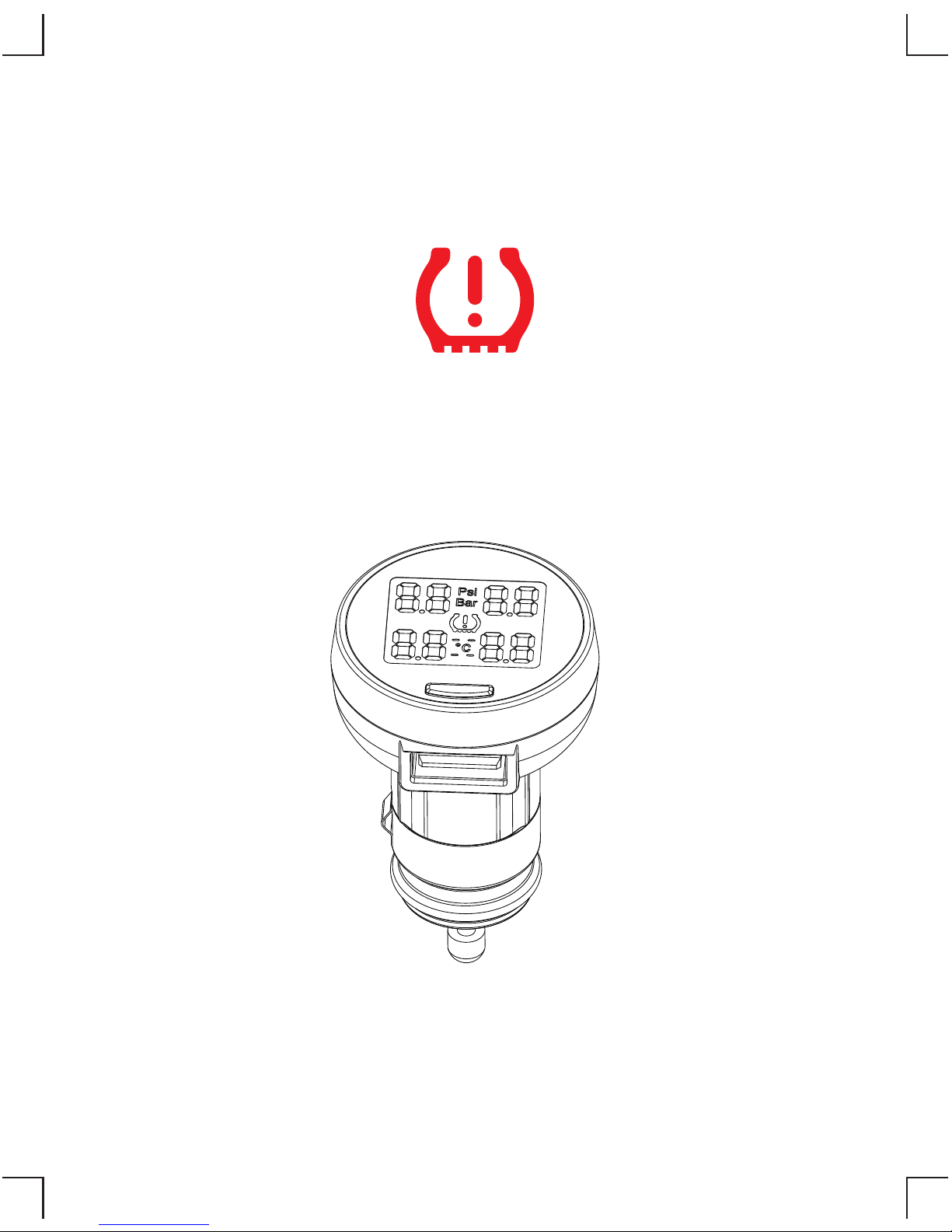
TPMS
TP200 USER’S MANUAL
V6.03.21

CONTENTS
1
Packing List .................................................................................... 2
Standard Tools and Accessories ....................................................... 3
Display Power On .......................................................................... 4
Installation of tire sensors.................................................................. 5
Driving checking ............................................................................. 6
USB charging Socket ...................................................................... 6
Display Functions ........................................................................... 7
Temperature Query .......................................................................... 8
SET Button Functions ................................................................... 10
Pressure Unit Switching ................................................................ 10
High pressure alarm value setting ( Factory default 46Psi) ............. 11
Low pressure alarm value setting ( Factory default 26Psi) ............. 12
Display and Sensor Code Learning ............................................... 13
2 Ways to Exit Code Learning Mode ............................................. 15
Sensor Exploded View ................................................................. 16
A: Replace Sensor Battery ............................................................. 17
B: Replace Sensor Battery ............................................................ 18
Leakage Reasons of Nonstandard Tire Valve ................................ 19
Technical Parameter: .................................................................... 20
FAQ .............................................................................................. 20
Notes and Statement ...................................................................... 21
2
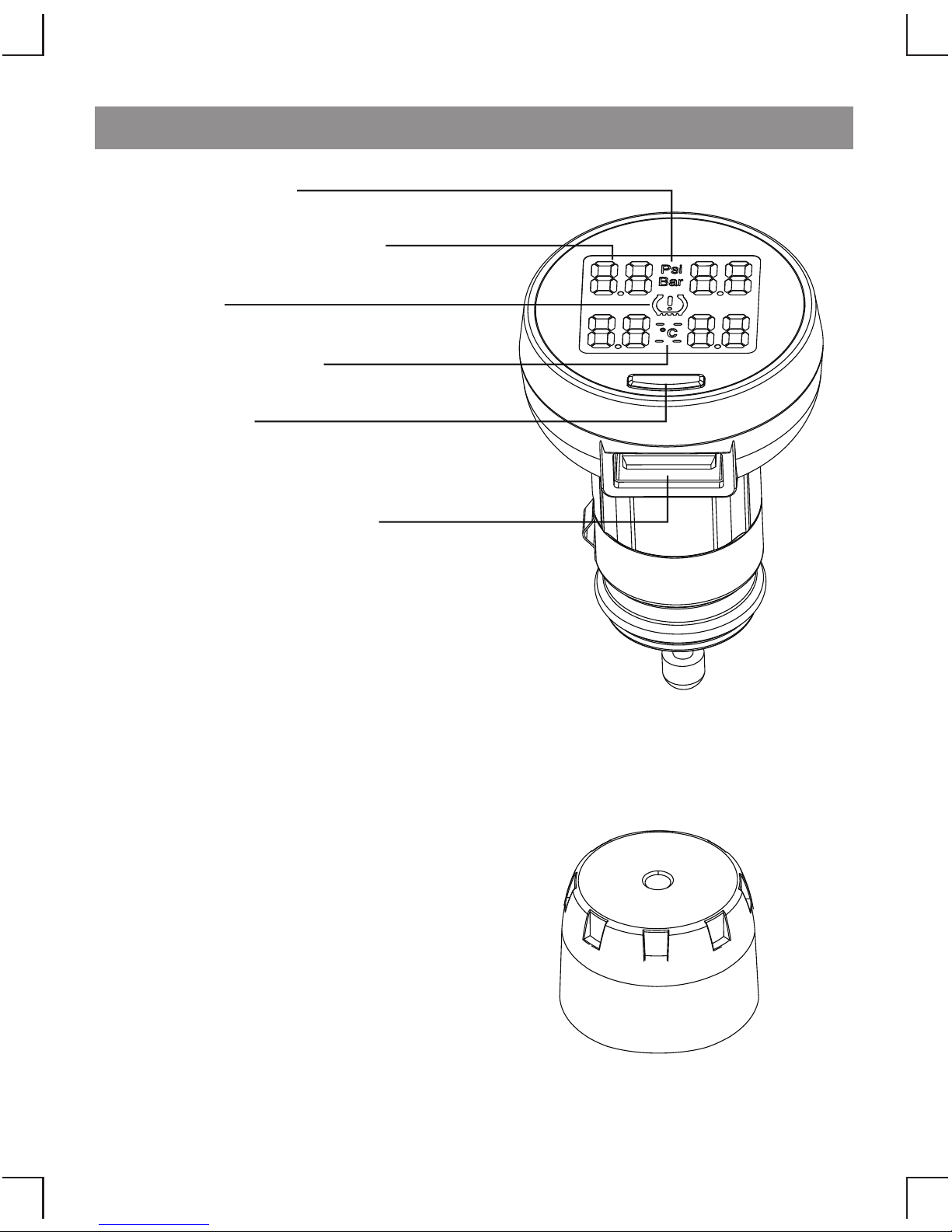
Packing List
Pressure Unit
Warning
Value of Tire Pressure
Temperature Unit
SET Button
USB Charging Socket
Display
Sensor 4pcs
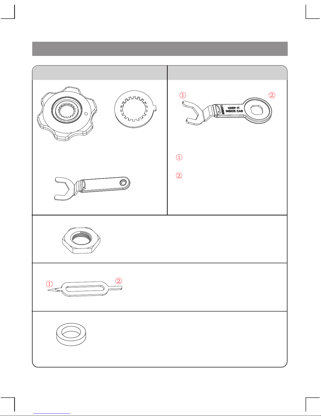
Uncap Wrench
(for replacing battery)
Hexagonal Nut 5pcs (one for backup)
Nut Wrench
Anti-dismantle
Locking Plate
2pcs(for backup)
If the silicon seal ring is damaged, please replace it by the
backup ring for avoiding leakage.
As shown in page 17 picture 3 - Replace Sensor Battery.
( for replacing the silicon seal ring)Ring Needle
①
②
for pulling out the silicon seal ring
for setting the silicon seal ring
Silicon Seal Ring 4pcs(for backup)
Standard Tools and Accessories
for locking the sensor with
hexagonal nut
A: Tools and Accessories
B: Tools and Accessories
For fixing the sensor base when
unscrew the sensor cover to
replace battery
Combination Wrench
3
4
1
2
ON
3
4
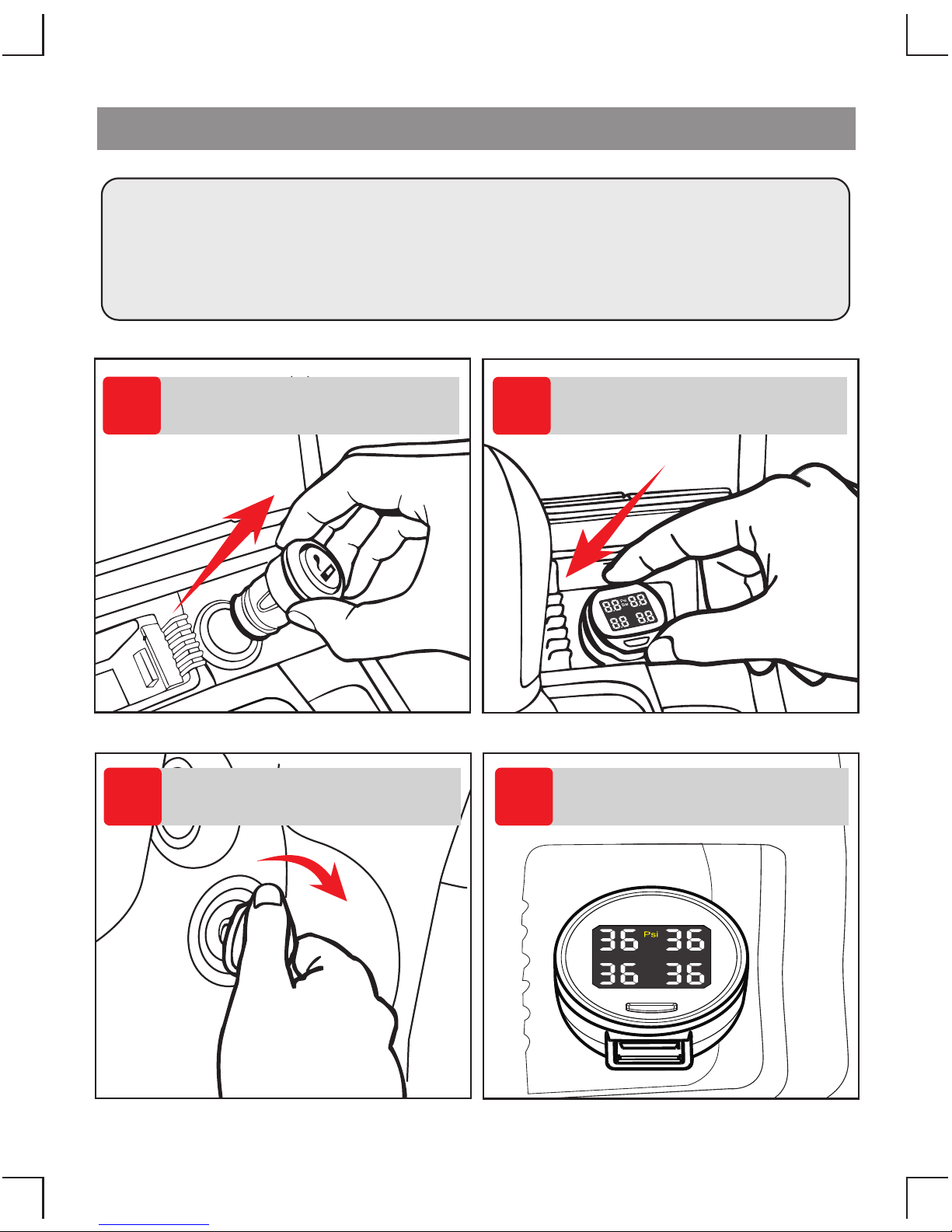
Display Power On
Pull out the cigar lighter
Plug in the display
ACC ON
Display power on,
and start to receive data.
Important:
Before installing the sensors, display must be plugged in
and vehicle key turned from ACC.OFF to ACC.ON.
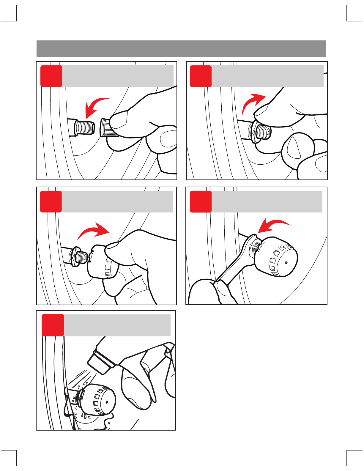
5
1
Backout dustproof cap
of tire valve.
2
Screw- in the
hexagonal nut.
Screw- in the sensor in
proper tire according to
the mark in the .Cover
3
Tighten the sensor by
nut wrench in reverse
direction.
4
5
Check if it is leaking
with soapsuds.
Installation of tire sensors
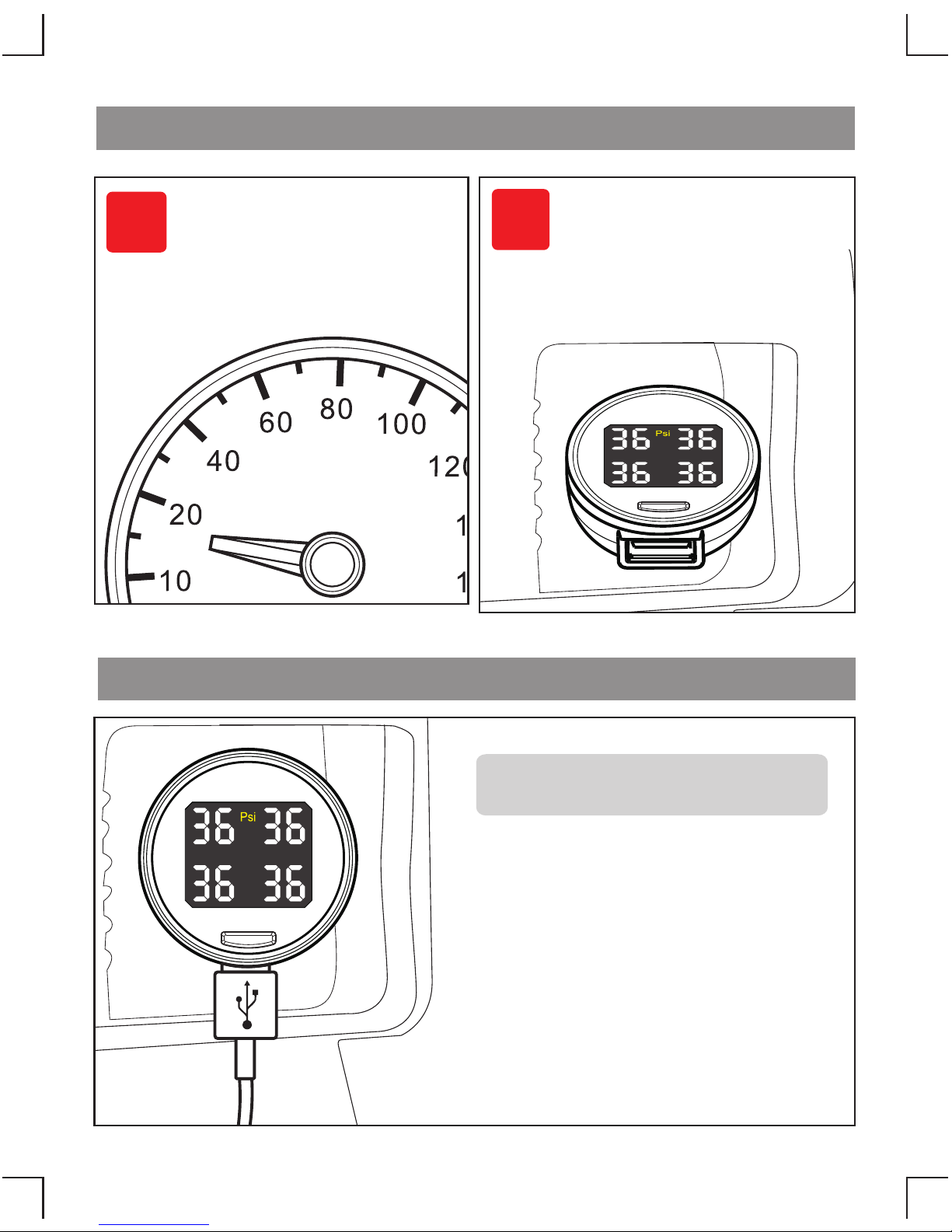
6
>15km/h
1
2
Driving Checking
When the driving speed
is up to 15km/h, the
display will update the
data of tire pressure
automatically.
There is a USB socket in display,
it can charge some portable
products such as mobile phone or
MP3 while the tire pressure
monitor is working.
Output voltage: 5V
Output current: 1A
USB Charging Socket
With display power on
If all the 4 tire pressure
values are shown, it means
the system installed and
working successfully.
 Loading...