

SyxthSense SST-A24-302, SST-A24-304, SST-A24-306, SST-A230-302, SST-A230-304 User Manual
...
Online store: www.syxthsense.com
Enquiries: T: 0844 840 3100 F: 0844 840 3200
PS TH6.90 - 1/5
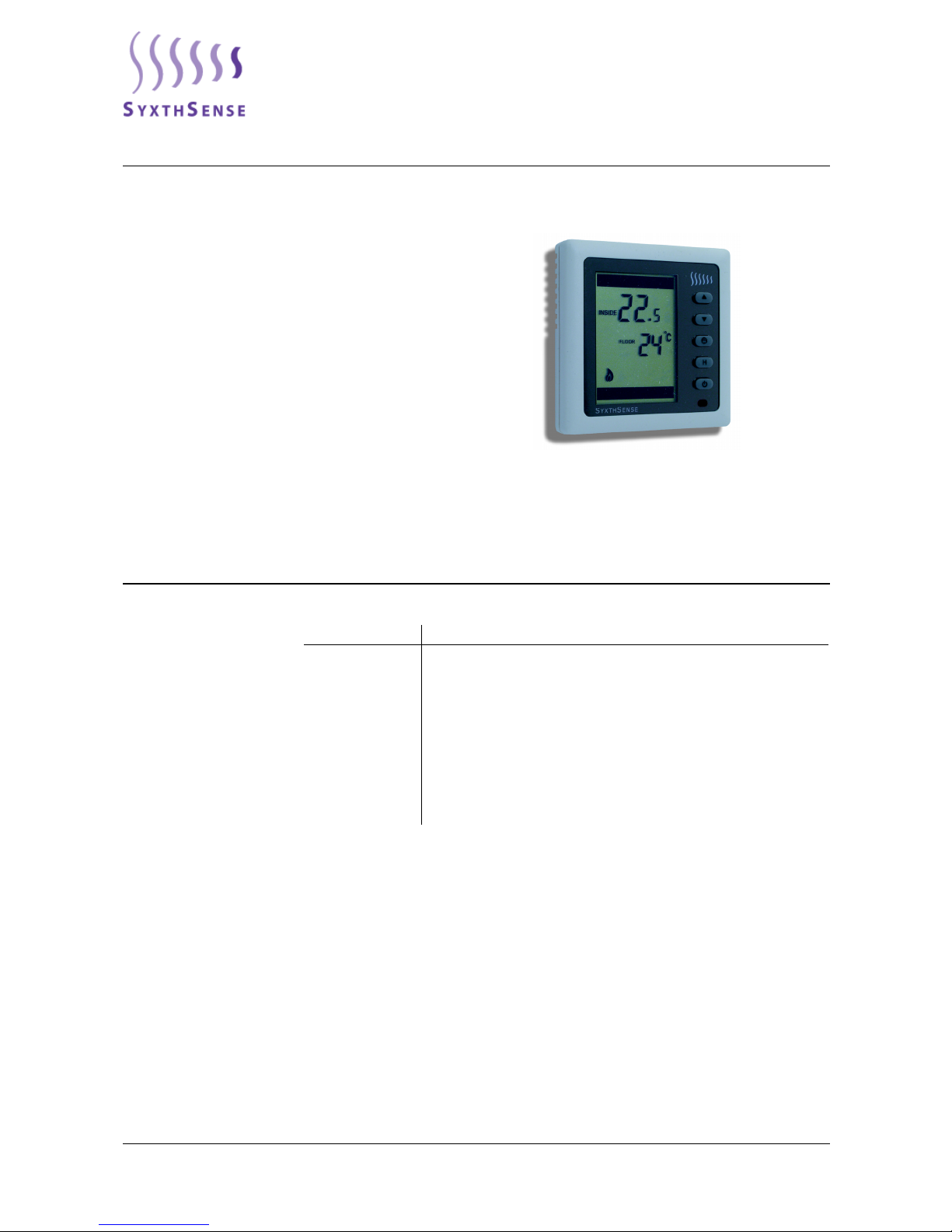
SST Series Digital Thermostats
SST series are elegant thermostats with a large clear LCD screen.
The thermostats are operated with five high quality buttons. The
SST range is available with a range of models to suit most heating
applications.
The SST thermostats can be extensively applied for residential,
indu
strial and commercial environment. The thermostats have
switching rating of up to 16A 230V making them suitable for both
wet systems and electrical heating systems.
Depending on the model, the thermostats can operate using
inter
nal or external sensor and can have an additional high limit
floor sensor.
The SST range has RS485 communication capability making them
idea
l for multi-zone and for high energy efficiency applications.
Features
• 24VAC or 230VAC Power Supply
• Large Digital Display with Back-Light
• Flush Mounted for Sophiticated Look
• Switching rating up to 16A 230V
• Celcius / Fahrenheit Display
• Low Temperature Protection
• Unique Lockable Keypad
• RS-485 Modbus Communication Network
• All temperature readings and settings ava
ilable via Network
Product sheet TH6.90
Thermostat Type SST
Model Type Model Description
SST-A24-302 Digital Thermostat, 24Vac, Floor Sensor
SST-A24-304 Digital Thermostat, 24Vac, Internal/External Sensor
SST-A24-306 Digital Thermostat, 24Vac, Internal/External and Floor Sensor
SST-A230-302 Digital Thermostat, 230Vac, Floor Sensor
SST-A230-304 Digital Thermostat, 230Vac, Internal/External Sensor
SST-A230-306 Digital Thermostat, 230Vac, Internal/External and Floor Sensor
SST-RB-01 Flying Lead Floor Temperature Sensor
SST-RC02 Infrared Remote Control for the Room Thermostats
TEFM-NTC100K Flush Mounted NTC100k Temperature Sensor
Technical Data Power Supply A24 Models: AC24V ± 10%, DC24V
A230 Models: AC230V ±10% 50/60Hz
Power Consumption < 1W
Switching Voltage AC220V ± 10% 16A SPST N/O (Resitive Load)
Output Signal ON/OFF
Measurement Range 5..95°C
Accuracy 0.5°C/F
Working Temperature 0..70°C
Sensor Characteristics NTC100kOhm
Setpoint Range 5 to 95°C/F
Terminals Max 2.5 mm
2
(min 0.5mm2)
Communication RS485 Modbus RTU, up to 32 devices (logical address range 1..32)
Modbus Settings 9600 baud, 8 Data Bits, None Parity, 1 Stop Bit, Maximum Setpoint
Writes 100,000 Cycles (Holding Register)
Color White with Glass Panel
SyxthSense Ltd
Copyright © 2013 SyxthSense Ltd. All rights reserved - 02/2013
PS TH6.90 - 2/5
Online store: www.syxthsense.com
Enquiries: T: 0844 840 3100 F: 0844 840 3200
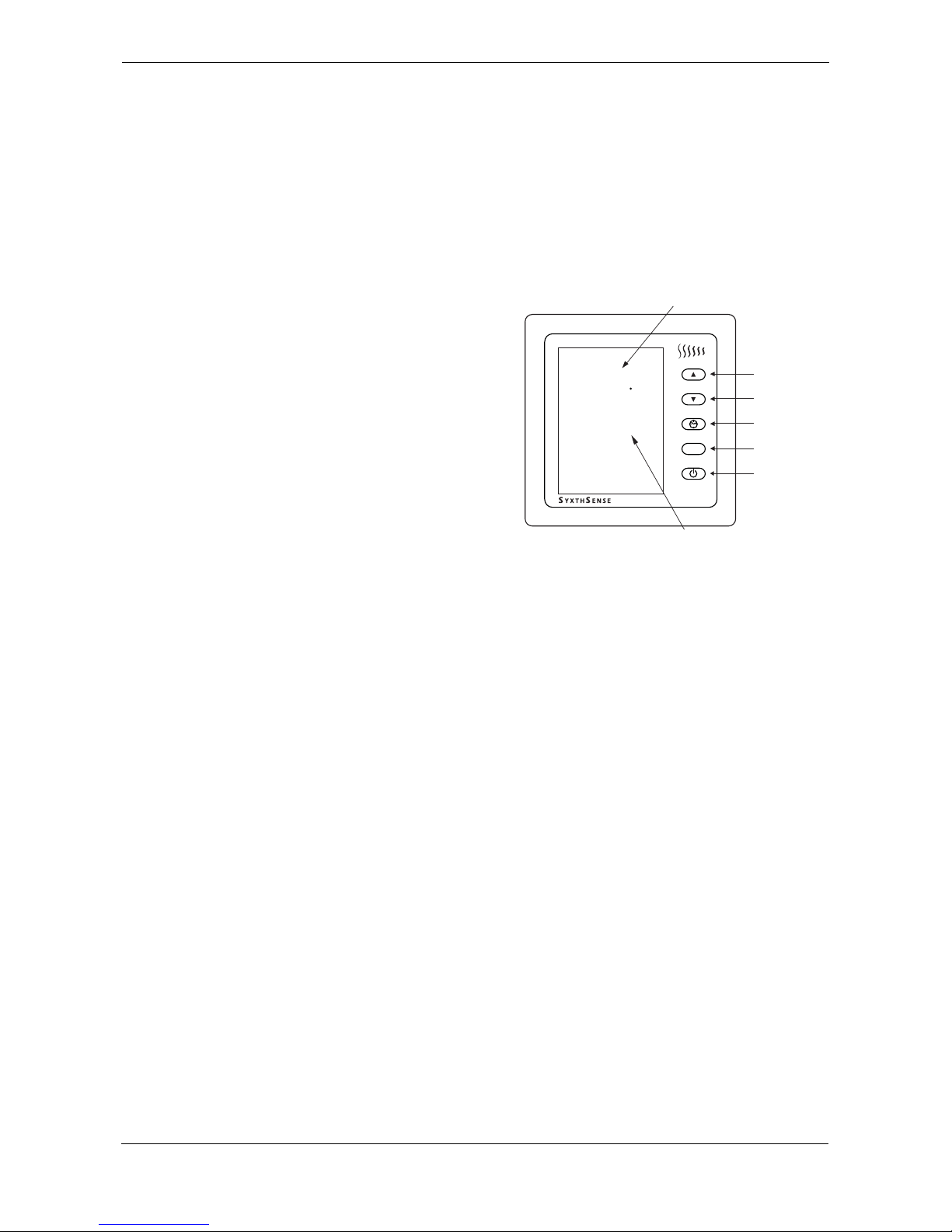
Operating Instructions Unit On/Off
UP button
DOWN button
CLOCK button
(not in use)
HOLD button
OFF button
H
20
5
INSIDE
SET
TEMP
20
°C
Current Setpoint
(Resolution 1°C)
Current Temperature
(Display Resolution 0.5°C)
Press OFF button to turn ON or OFF
the thermostat.
Temperature Setting
When the thermostat is ON, press UP
or DOWN butto
ns to set the desired
temperature. If the temperature is set
at "- -", the thermostat is disabled.
Manual Temperature Override
When the thermostat is ON, press the
button H t
o display the HOLD icon.
The thermostat is overridden ON at
the current setpoint until the override
has been cancelled. The HOLD
button is a quick way to freeze the
current setpoint.
Keypad Lock Function
Simultaneously press UP and DOWN
buttons for 1
0 seconds to lock the thermostat. The LOCK icon is displayed on the thermostat. In this
mode it is not possible to adjust the temperature setpoint. As default it is possible to switch the
thermostat OFF. All user interactions can be disabled via advanced configuration parameters.
To unlock the thermostat, press UP and DOWN buttons again simultaneously for 10 seconds. The
LOC
K icon on the thermostat disappears.
Thermostat ON/OFF Timer (with Remot
e Control only)
When this function has been set via remote control, the
TIMER icon is displayed together with the
counting down time.
Error Display
When errors occur on the themostat, the ERROR ico
n is displayed together with error code. The
following list describes the error codes.
• 1 =Internal Temperature Sensor Error
• 2 =External Temperature Sensor Error (if re
quired change the sensor selection under the
advanced configuration options)
• 3 = Floor Temperature Sensor Error
• 10 = Internal Data Storage Display
Communication Display
When the COMMUNICATION icon is displayed, the ther
mostat is communicating with the network
master.
Low Temperature Protection The thermostats has low temperature protection feature.
If the measured temperature drops below the
frost setpoint (default 7°C), the thermostat relay is switched ON even if the thermostat has been
turned off from the ON/OFF button.
The Low Temperature Protection feature can be disabled in the Advanced Configur
ation Parameters.
Housing ABS Flame Retardant
Mounting
Flush Mounting (wall mounting using a separate box)
Dimensions W86 x H86 x D14.5 mm
Environmental Conditions Operating Temp 0..+50°C
Humidity Limits 0..95% rH non-condensing
Storage Temp -20..+50°C, Humidity <95% rH
Environmental
Standards
IEC721-3-3, Climatic Conditions Class 3K5
EN 60730

GND
B
A
N
0V Common
L
N
A
B
ST1 (RS)
N
Remote Sensor*
M
ST2 (FS)
LOAD
L
Floor Sensor*
RS-485
Modbus
* Depending on model
SST THERMOSTAT
220 VAC
LOAD
≤ 16A
SwL
e.g
N
M
Zone Valves
Electric Load
Boiler
24VN
B
A
N
0V Common
L
N
A
B
ST1
N
Remote Sensor*
M
ST2
LOAD
L
Floor Sensor*
RS-485
Modbus
* Depending on model
SST THERMOSTAT
220 VAC
LOAD
≤ 16A
SwL
e.g
N
M
Zone Valves
Electric Load
Boiler
24VL
24VN
24VAC / 24 VDC (+)
0VAC (-) / 24 VDC (-)
SyxthSense Ltd
Copyright © 2013 SyxthSense Ltd. All rights reserved - 02/2013
PS TH6.90 - 3/5
Online store: www.syxthsense.com
Enquiries: T: 0844 840 3100 F: 0844 840 3200
Wiring Details (230VAC
Ver sion s)
WARNING: The electrical wiring is to be carried out by qualified electricians and is required to
comply with the local wiring and electrical regulations.
Wiring Details (24VAC
Ver sion s)
The electrical wiring is to be carried out by qualified electricians and is required to comply
wit
h the local wiring and electrical regulations.
Advanced Parameter
Settin
gs
Advanced parameter settings are used to re-configure the SST Thermostat operation. Exact settings
used depend on the model.
To enter the configuration mode, switch the thermostas OFF (from OFF button). Then press the HOLD
("H
") button conitnuously up to 10 seconds to display the first of the configuration paratemers. To
adjust the setting press UP or DOWN button until the required setting is displayed.
To advance to the next parameter press HOLD (
"H") button again. Continue until all required
parameters have been set. At any time the configuration can be exited by pressing the OFF button,
and the normal operation resumes.
WARNING: Use care when changing the advanced configuration parametes as these affect the
op
eration of the thermostat.
Parameter Parameter Description Available Settings Default
1 Thermostat Operation when power is
Applied
0 - Thermostat OFF when power is applied
1 - Thermostat ON when power is applied
2 - Retain last status when power is applied
2
2 Keypad Lock Status 0 - Function is disabled
1 - Temperature adjustment available only
2 - ON/OFF button workable only
3 - All buttons locked
2
3 Sensor Selection 0 - External temperature sensor
1 - Internal temperature sensor
2 - Internal sensor is used for normal control. The
remote sensor connections (RS and 0V) are used as
a volt free contact to override the SST Mode of
control. Open Contact = OFF, Closed Contact = ON
(for more information see external override section)
1
4 Unit Selection 0 - Celcius display enabled
1 - Fahrenheit display enabled
(when changed the calibration and all switching
temperature settings return to default values)
0

SyxthSense Ltd
Copyright © 2013 SyxthSense Ltd. All rights reserved - 02/2013
PS TH6.90 - 4/5
Online store: www.syxthsense.com
Enquiries: T: 0844 840 3100 F: 0844 840 3200
External On/Off Override
(e.g. telephone interface)
If an external sensor is not in use
an advanced setting can be
activated to override the SST
thermostat remotely on/off. This
can be used, for example, with a
telephone or mobile text message
interface for remote heating
switching.
GND
B
A
N
RS
N
FS
LOAD
L
SST THERMOSTAT
Remote Override
Switch e.g telephone
interface or GSM interface
Contact Open
= Thermostat OFF
Contact Closed
= Thermostat ON
(SyxthSense part nos
ITPF-221 and ITPR-321).
To activate this function configure
the Advanced Paramet
er No. 3 to a
setting 2.
If the unit is remotely overridden
OF
F, the unit can be locally
overridden ON by pressing OFF
button. Note: The thermostat
needs to detect close to open
transition to switch again off
remotely.
5 Temperature Sensor Reading Adjust When viewing parameter 5 on the SST, the current
room temperature is shown. The user may then
adjust this reading by using UP/DOWN keys to
match the user preference (0.5°C steps). The
maximu effect on the sensor is +/-10°C.
Example: SST Reading = 21°C, Handheld
Thermometer Reading 23.5°C. Parameter 5 must be
accessed and UP arrow keyed until the display
shows 23.5°C. Press the ON key to store/show the
new reading. The SST will display 23.5°C as a the
temperature in the room has not changed during the
setup.
NOTE: Changes to the parameter 5 will be applied to
all sensor inputs on the SST being adjusted.
N/A
6 Lowest Setpoint Allowed 5..95
(The value of the lowest setpoint that a user can
program into the SST. Any setpoint attempted to be
lower than this setting willbe returned to this value.)
5
7 Highest Setpoint Allowed 5..95
(The value of the highest setpoint that a user can
program into the SST. Any setpoint attempted to be
higher than this setting willbe returned to this value)
35
8 Temperature Control Hysteresis 1, 2 or 3 Degrees 1
9 Low Temperature Protection 0 - Disabled
1 - Enabled (when thermostat is turned off)
1
10 Low Temperature Protection Ranges Celcius: 5..17°C
Fahrenheit: 41..63°F
7
11 Network Address (Modbus Slave) 1..32 1
12 Sleep Mode Not Applicable 1
13 Floor Sensor Limit Temperature Adjustable between 5..95°. If adjusted above 95°, the
LCD displays "--" and the floor temperature limit will
be disabled
28
14 12/24 Hour Time Mode Not Applicable 0
15 Four Switching Period Default Settings Not Applicable 07:00 20/68
09:00 16/61
16:00 20/68
23:00 16/61
Parameter Parameter Description Available Settings Default

SyxthSense Ltd
Copyright © 2013 SyxthSense Ltd. All rights reserved - 02/2013
PS TH6.90 - 5/5
Online store: www.syxthsense.com
Enquiries: T: 0844 840 3100 F: 0844 840 3200
Dimensions Please find the below diagrams fro the thermostat dimensions. The dimensions are in millimetres. The
mounting hole center points are 60 mm apart.
NOTE: A 35mm
deep wall box is recommended.
Notes: In the view of a constant development of their
products, the manufacturer reserves the right for changing
technical data and features without prior notice.
The consumer is guaranteed against any lack of conformity
for 24 months from the time of delivery, according to the
European Directive 1999/44/EC. The full text of guarantee
is available on request from the seller.
86
86
41
62
41
39.5
25
Networking A maximum of 32 SST devices can be connected onto a single Modbus network. For more about
available Modbus communication parameters please refer to the SST Modbus Communication
Manual.
Please observe the following networking wiring precautions:-
• Max. Cable Length 1000 meters.
• LAN termination jumpers must be fitted to each device at the end of network
• Use Belden 8762 cable. Same for remote sensors.
GND
B
A
N
RS
N
FS
LOAD
L
SST THERMOSTAT
GND
B
A
N
RS
N
FS
LOAD
L
SST THERMOSTAT
GND
B
A
N
RS
N
FS
LOAD
L
SST THERMOSTAT
GND
B
A
MODBUS MASTER
e.g. WebBiter
A = RS485 +ve
B = RS485 -ve
GND = Common 0V
= End of Line Termination
All communication cable
is Belden 8762 or equivalent.
Protecting shield is connected
to Earth
Box Contents The SST thermostat box contains the following:-
• 1 off SST Thermostat shipped with anti-static film over LCD screen
• 1 off Network termination jumper (only use
d when SSTs are connected on a communication net-
work)
• 2 off 25 x M3.5mm fixing screws
 Loading...