

Sysvideo SN7208, SN7216, SN7000 series, SN7200 series, SN7232 Instruction Manual
...
Sysvideo Technology Limited
1
The Manual of Network Video Recorder
2013.6

Sysvideo Technology Limited
2
Directory
1 Precautions.....................................................................................................................................4
2 Declaration.....................................................................................................................................4
3 Product Introduction ......................................................................................................................4
3.1 Product Overview ...............................................................................................................4
3.2 Feature.................................................................................................................................5
4 Installation......................................................................................................................................5
4.1Unpacking Inspection ..........................................................................................................5
4.2 Installation Preparation .......................................................................................................5
4.3 Installation of the burner .....................................................................................................6
4.4 The Front Panel.............................................................................................................6
4.4.1 SN7200 Series.......................................................................................................... 6
4.4.2 SN7800 Series...................................................................................................7
4.5The Rear Panel.....................................................................................................................9
4.5.1 SN7200 Series...................................................................................................9
4.5.2 SN7800 Series.................................................................................................10
4.6 The Alarm Cable ...............................................................................................................10
4.7 The Connection of POE ....................................................................................................11
5 Basic Operations Guide ...............................................................................................................11
5.1 Power On and Off .......................................................................................................11
5.1.1 Power On................................................................................................................11
5.1.2 Power Off ........................................................................................................ 11
5.2 Preview and Login in ..................................................................................................12
5.2.1 Preview...................................................................................................................12
5.2.2 Login In...........................................................................................................12
5.3 Mode Switching ................................................................................................................ 13
5.4 IP Camera....................................................................................................................13
5.4.1 Add IP Camera................................................................................................13
5.4.2 Status Display..................................................................................................14
5.5 PTZ Control ......................................................................................................................14
5.5.1 PTZ configuration ...........................................................................................15
5.5.2 Quick location .................................................................................................15
5.6 Search................................................................................................................................16
5.7 Record ...............................................................................................................................17
5.8 Alarm ..........................................................................................................................17
5.8.1 Alarm Output..........................................................................................................17
5.8.2 Alarm Configuration .......................................................................................17
5.8.3 Alarm Status....................................................................................................19
5.9 Color Setting .....................................................................................................................19
5.10 The Input Method............................................................................................................20
6 Parameter Settings .......................................................................................................................20
6.1 Introduction OfMain Menu...............................................................................................20

Sysvideo Technology Limited
3
6.2 Video Settings ...................................................................................................................20
6.2.1 Basic................................................................................................................20
6.2.2 Encoding settings ............................................................................................21
6.2.3 Snapshot ..........................................................................................................21
6.2.4 Net Channel.....................................................................................................22
6.3 Record ...............................................................................................................................22
6.4 Network.............................................................................................................................23
6.5 PTZ Configuration ............................................................................................................25
6.6 Alarm ..........................................................................................................................26
6.6.1 Video Detection......................................................................................................26
6.6.2 Alarm input .....................................................................................................26
6.6.3 Alarm out ........................................................................................................27
6.7 System.........................................................................................................................27
6.7.1 Base........................................................................................................................27
6.7.2 Display ............................................................................................................28
6.7.3 Storage.............................................................................................................28
6.7.4 Abnormity .......................................................................................................30
6.7.5 Status...............................................................................................................30
6.7.6 Maintain ..........................................................................................................30
6.7.7 Account ...........................................................................................................31
6.7.8 RS232..............................................................................................................32
7 Web and Client.............................................................................................................................32
7.1 Web Operation ..................................................................................................................32
7.1.1 Network Connection ..............................................................................................32
7.1.2 The control installation and the user login logout..................................................33
7.1.3 The Interface of Web Operations ...........................................................................34
7.1.4 The Real-time Monitoring......................................................................................34
7.1.5 PTZ Control ...........................................................................................................36
7.1.6 Configuration .........................................................................................................36
7.1.7 Search Record ........................................................................................................37
7.1.8 Alarm Configuration ..............................................................................................38
7.1.9 About......................................................................................................................38
7.2 The Client Operations .......................................................................................................38
8Appendix.......................................................................................................................................39
8.1 Expansion function .....................................................................................................39
8.1.1 DDNS Function......................................................................................................39
8.1.2 PTZ Control ...................................................................................................................42
8.2 HDD Capacity Calculation .........................................................................................43
8.2.1 Reference of HDD Capacity Calculation...............................................................43
8.2.2 Hard disk problem...........................................................................................43
8.3 Common Faults.................................................................................................................45

Sysvideo Technology Limited
4
1 Precautions
The following content is about use of the product,the prevention of danger as well as preventing
property from the loss.Please be sure to comply.
1, Please placed NVRs within the permissible range of temperature and humidity.
2, Do not install the NVRs in a damp, dust or soot place.
3, Place the product horizontally and pay attention to preventing it from falling.
4, Installed in a well-ventilated place and do not block the vent.
5, Do not place containers filled with on the device.
6, Do not place other equipments above the product.
7, Do not disassemble this product.
8, Please select the hard disk recommended by manufacturers and suitable for the requirements of
the NVR.
2 Declaration
Please prevail in kind.The manual is for reference only.
This manual may contain inaccurate data or printing error.
The products described in this manual may be updated at any time.
Screenshots of the manual is not in a machine and only for display.
If in doubt, obtaining a copy of the latest procedure or the additional document, please contact
with the company's after-sales department.
3 Product Introduction
3.1 Product Overview
This product is designed specifically for the field of video surveillance and adopts H.264 video
compression, hard disk recording, TCP/IP transmission and a Linux based OS in addition to some
of the advanced technology in the information technology industry. This enables a more stable,
reliable and high picture quality.This product complies with standards of GB 20815-2006《video
security surveillance digital video recording》promulgated by the State. At the same time, the
product supports the ONVIF protocol(base on《ONVIF ™ Core Specification》Version 2.2) and is
compatible with the network cameras which supports ONVIF protocol.This product can realize
the switching of NVR mode or mixed mode (Mixed mode can both connect with analog
channels and network cameras when the NVR modes only connect with network
cameras) ,recording, playback, monitoring, synchronization of audio and video.Besides,the
products support advanced control technology and strong network data transmission capacity.

Sysvideo Technology Limited
5
3.2 Feature
Real-time monitoring
Have a composite video signal interface and support TV, VGA or HDMI output simultaneously.
Compression function
Use H.264 video compression standard and G.711 audio compression standard and have high
definition, low code rate of the video coding and the storage.
Recording function
Support timing,linkage alarm, motion detection,SATA hard and local hard disk , NVR data backup
and network backup.
Video playback function
Achieve searching videos by a variety of conditions,playback in local and network. Support
multiple videos playback,fast playing,slow playing and frame-by-frame playback.Video playback
can display the exact time of the incident.Provide timeline retrieving page for quick searching.
Camera control and alarm
Be controlled by the remote camera and equip many alarm input interfaces.Be connected to
various types of alarm devices.Dynamic detection, video loss, video block,multiple alarm output
and scene lighting control can be realized.
Communication Interface
Equip USB 2.0 high-speed interface or ESATA interface and allow many backup devices. Equip
standard Ethernet interface.Plug and play in a variety of network conditions,
Network functions
Support TCP / IP, UDP, RTP / RTSP, DHCP, PPPOE, DDNS, NTP etc.Support real-time network
monitoring, video playback, control and management functions; built-in WEB Server, you can
directly access through a browser.
Mode of operation
You can operate by the front panel or the mouse.Equip a simple, intuitive graphical interface.
4 Installation
4.1Unpacking Inspection
When you receivea product, check it according to the packing list inside the box.
4.2 Installation Preparation
Preparation
Sysvideo Technology Limited
6
Prepare a Cross Screwdriver.
Steps
Remove the metal top cover by removing two screws from the sides of the cover.
Place the hard disks on a flat table and tighten the screws.
Connect the power and the data lines to the HDD.
Reinstall the metal top cover and tighten the screws.
Caution
Only use the HDD specified by the manufacturer.
The HDD will be formatted automatically during booting and it may cause data loss.
The total duration of video data saved is decided by the HDD’s capability and the NVR’s
parameters (recording setup, encoding setup). Please refer to 9.3.
4.3 Installation of the burner
Preparing for Installation
You need a Phillips screwdriver.
The burner installation steps
Unscrew the screw on the side of the chassis and open the case cover.
Use a screwdriver to remove the bracket fixed in middle of the disk.
Open the front panel door and remove the baffle inside.
Connect the burner data cable and the power cord.
Fix the chassis cover.
Precautions
The installation of the built-in burner is only for specific NVR and affects disk space for
installation and interfaces.
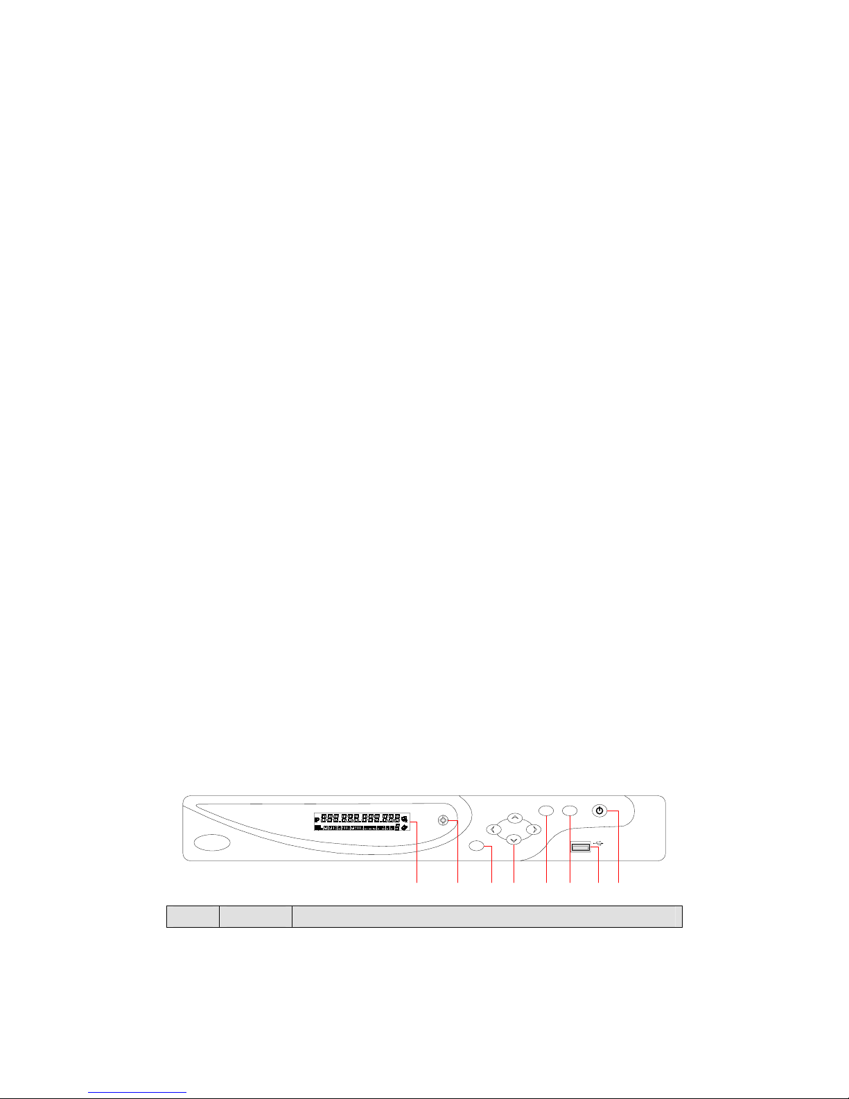
4.4 The Front Panel
4.4.1 SN7200 Series
Index Name Function

Sysvideo Technology Limited
7
1 LCD
1, IP address of the device,the clock,the external alarm
channel,error status code of the machine, remote address, internal
temperature of the chassis is displayed.
2, Network Connection status.
3, HDD status and numbers. “E” and flash label refer HDD error.
4, Cycling display the recording status and motion detection
(distinguish by “REC” and“MOVE”).
2 IR Receive the remote control signal.
3 Esc
Back to previous menu, operation cancel;
Back to live view when playing back records.
4 Direction
Up/Down: Move up or down.Change the settings and increase or
decrease the digital.
Left/Right: Control the playback control bar of the records.
5 Enter
Confirm the operations.
Jump to the default button.
Enter the menu.
6 Fn
The button displays PTZ control and image color when in a
single-screen monitoring.
Simultaneously press the Fn key and the direction key to complete
the settings with the dynamic monitoring area.
Press the Fn key to empty all contents of the edit box.
Press the key to switch between the digital casein English, Chinese
input.
Special with the function of each menu page prompts.
7 USB To connect the mouse and HDD.
8 ON/OFF Power on/off.
4.4.2 SN7800 Series
Index Name Status Function
1 The power Power Power on/off

Sysvideo Technology Limited
8
2 Shift ↑
Switch the TAB page.
Press 3 seconds to switch into the panel input
status.
When activate the input box,activate the input
method and switch the state of the input
method.
3 Numeric area 1~9
Digital input
Text input
Image switching
4 Figure +10
The input of numbers more than 10:press the
key and input two number to produce a 2-digit
numeric.
5
The up and
down keys ↑↓
Up/Down: Move up or down.Change the
settings and increase or decrease the digital.
6
The left and
right keys ←→
Left/Right: Control the playback control bar of
the records.
7 Cancel/Exit ESC
Close the control window or back to the
previous menu.
8 Firm key ENTER
Confirm operations.
Jump to<confirm> options.
Bring up the main menu in the real-time
monitoring screen.
9
The
recording
key
●
Bring up the video control menu in the
real-time monitoring screen.
Enter to set the preset in the PTZ control menu.
10
The function
auxiliary key Fn
The button displays PTZ control and image
color when in the state of the single-screen
monitoring.
Simultaneously press the Fn key and the
direction key to complete the settings with the
dynamic monitoring area.
Press the Fn key to empty all contents of the
edit box.
Press the key to switch among figure, English,
Chinese input.
Special with the function of each menu page
prompts.
11
The play /
pause key
▶
Play.
Come to normal when rewind.
Resume playback when pause.
Enter into inquiry menu when real-time
monitoring.

Sysvideo Technology Limited
9
PTZ control: Zoom +.
12
the shuttle
outside
The same with the direction key
13
the shuttle
inside
The same with the direction key
4.5The Rear Panel
4.5.1 SN7200 Series
SN7208 Rear Panel Interfaces
SN7216 Rear Panel Interfaces
SN7232 Rear Panel Interfaces
Sysvideo Technology Limited
10
4.5.2 SN7800 Series
SN7832 Rear Panel Interfaces
Index Name Description
1
The
video/audio
output
The input interface of the audio signal
2
The network
interface
The network interface of RJ-45
3
The VGA
interface
The output interface of the VGA video signal
4
The power
input
The power input interface
5 the terminals
The interface of the alarm input,the alarm output and
RS-485
6
The HDMI
interface
The output interface of the HDMIvideo signal
7
The power
switch
The power switch
8
the peripheral
interface
The ESATA interface and the 232 serial port.
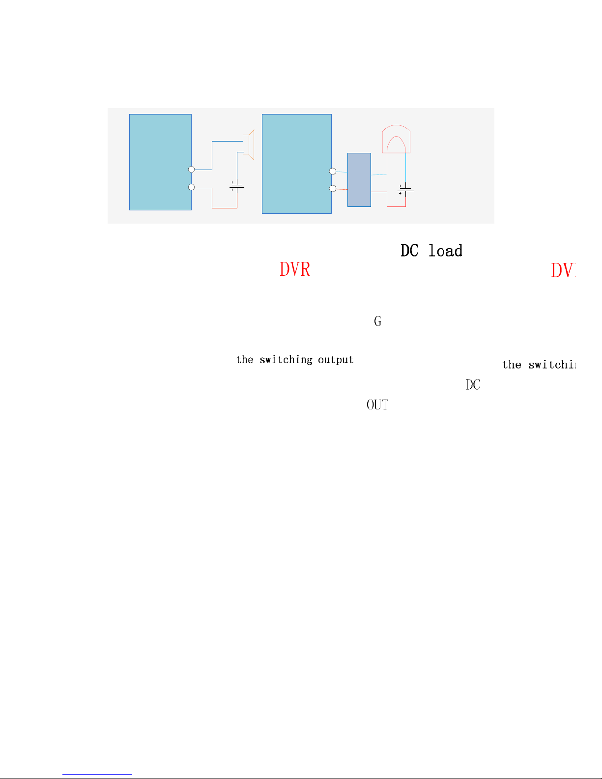
4.6 The Alarm Cable
Examples of alarm input connections
The alarm input is the switch quantity input. If the alarm input signal is not switch quantity signal
but voltage signal, refer to the following connection.
Sysvideo Technology Limited
11
Examples of alarm output connections
When the alarm output connect with DC and AC load, please refer to the connection.
4.7 The Connection of POE
Step 1: Supply the NVR with the 12V DC power.
Step 2: Connect the POE module with 48V directly power.
Note:48V voltage is not safe, please pay attention to the use of electricity.
Step 3: The side of the network cable is connected to the POE network interface and the other side
is connected to the network camera. The distance of POE power i s not more than 100 m
theoretically.
5 Basic Operations Guide
5.1 Power On and Off
5.1.1 Power On
Correctly install and power on the NVR. When the power indicator lit up, the VCR will
automatically start.NVR will automatically detect hardware state of the device during the starting.
The booting process will continue for about 30 seconds. After boot, the equipment sounds and
then enters the state of multi-screen real-time video surveillance.
5.1.2 Power Off
Press the power key for three seconds to achieve shutdown.Enter the NVR’s [main menu]-
shutdown] and select [shutdown].

Sysvideo Technology Limited
12
5.2 Preview and Login in
5.2.1 Preview
After the device is turned on, you will enter the real-time monitoring interface. Right click and the
following interface will pop up.
5.2.2 Login In
Click the image above with [main menu], and then input the user name(default:admin)and the
password of the NVR(default:empty)to complete the login.

Sysvideo Technology Limited
13
5.3 Mode Switching
The NVR can work in mixed mode or NVR mode. Mixed-mode can be connected with both
analog cameras and network cameras while NVR mode can only support IP cameras.
Enter [configuration]- [system]-[channel mode] to select the mode. Restart to complete the setting.
5.4 IP Camera
5.4.1 Add IP Camera
Network channels are used to display remote IPCs. The addition of IPCs shows as the following
interface.
Enter [video]-[net channel].
First open [OPEN].
[Channels]Choose a local channel to
display.
[Protocol]It is selected according to the type
that the IPC supports.
[IP] Input the IPC’s IP address.
[Port]Fill in the ONVIFport of the IPC.
[Username]Fill in the user name of the IPC.

Sysvideo Technology Limited
14
[Password] Fill in the password of the IPC.
[Remote Detect]After completing the above parameters, click the detect button to return the
connection status.
[Search]Select the appropriate protocol and
search.The IPCs and the device should in
the same LAN. Double click the search
results and it will add the IPC automatically
and return to theprevious page. Fill in the
user name and password to complete.
5.4.2 Status Display
Right click in the real-time monitoring screen and select [net channel] to view the status of the
network channels.
5.5 PTZ Control
When connect with a network ball, right click the corresponding network channel and select [PTZ]
to enter into thePTZ interface.If access to a simulated ball machine, enter [Main Menu] - [PTZ] to
modify the PTZ protocol, the baud rate and address bits. Then right click in the corresponding
channel and select [PTZ].The PTZ control interface is shown as the following interface.
 Loading...