


SYSTRONIK
Elektronik u. Systemtechnik GmbH
Gewerbestrasse 57
D-88636 Illmensee
Tel.: +49 (0) 7558 / 9206-0
Fax: +49 (0) 7558 / 9206-20
E-Mail: info@systronik.de
Internet: www.systronik.com
Read manual before use!
Observe all safety information!
Keep manual for future use!
11.2011 0 Systronik-Artikel-Nr.: 22794
854.001.0475
Instruction Manual
Flue Gas Analysis Computer
EUROLYZER® ST
EUROLYZER® STe

2 EUROLYZER® ST / STe
Contents
1 About this instruction manual .................................................................................. 4
1.1
Structure of warning ..................................................................................... 4
1.2
Explanation of symbols and typeface .......................................................... 4
2 Safety....................................................................................................................... 5
2.1
Intended use................................................................................................. 5
2.2
Predictable incorrect application .................................................................. 5
2.3
Safe handling ............................................................................................... 5
2.4
Qualification of personnel ............................................................................. 6
2.5
Modifications to the product ......................................................................... 6
2.6
Usage of spare parts and accessories ......................................................... 6
2.7
Liability information ...................................................................................... 6
3 Product description .................................................................................................. 6
3.1
Control panel (buttons and scroll function) .................................................. 7
3.2
Display .......................................................................................................... 8
3.3
Measurement and calculation parameters ................................................. 10
3.4
Measuring methods .................................................................................... 11
4 Technical specifications......................................................................................... 11
4.1
Calculation formulae (extract) .................................................................... 14
4.2
Approvals, tests and conformities .............................................................. 15
5 Transportation and storage ................................................................................... 15
6 Commissioning ...................................................................................................... 16
6.1
Connection diagram ................................................................................... 16
7 Program start ......................................................................................................... 17
8 Measuring programs and Settings menu .............................................................. 18
8.1
"Flue gas measurement" program ............................................................. 18
8.2
"Temperature measurement" program....................................................... 31
8.3
"Pressure measurement" program ............................................................. 32
8.4
"Settings" configuration menu .................................................................... 33
9 Memory mode & memory structure (option) .......................................................... 34
9.1
How to save................................................................................................ 39
10 Battery management ............................................................................................. 40
10.1 Battery mode/charging mode ..................................................................... 40
10.2 Charging the batteries ................................................................................ 40
11 Maintenance .......................................................................................................... 42
12 Troubleshooting ..................................................................................................... 42
13 Shutting down and disposal .................................................................................. 44

EUROLYZER® ST / STe 3
14 Spare parts and accessories ................................................................................. 44
15 Warranty ................................................................................................................ 45
16 Copyright ............................................................................................................... 45
17 Customer satisfaction ............................................................................................ 45
18 Addresses .............................................................................................................. 45
19 Appendix ................................................................................................................ 46
19.1 Bluetooth Declaration of Conformity .......................................................... 46
19.2 DIN EN 50379 Certificate ........................................................................... 47

About this instruction manual SYSTRONIK
4 EUROLYZER® ST / STe
1 About this instruction manual
This instruction manual is part of the product.
Read this manual before using the product.
Keep this manual during the entire service life of the product
and always have it readily available for reference.
Always hand this manual over to future owners or users of the
product.
1.1 Structure of warning
WARNING TERM
The type and source of danger is shown here.
Precautions to take in order to avoid the danger are shown
here.
There are three different levels of warning:
Warning term Meaning
DANGER
Imminent danger!
Failure to observe the information will result in
death or serious injuries.
WARNING
Possible imminent danger!
Failure to observe the information may result in
death or serious injuries.
CAUTION
Dangerous situation!
Failure to observe the information may result in
minor or serious injuries as well as damage to
property.
1.2 Explanation of symbols and typeface
Symbol Meaning
Prerequisite for an activity
Activity consisting of a single step
1.
Activity consisting of several steps
Result of an activity
•
Bulleted list
Text
Indication on a display
Highlighting
Highlighting

SYSTRONIK Safety
EUROLYZER® ST / STe 5
2 Safety
2.1 Intended use
The flue gas analysis computer EUROLYZER® ST/STe is exclusively suitable for:
• professional settings and control measurements at all small
combustion systems (low temperature and burner value boilers
and thermal systems) for gas, oil and pellet systems.
• measurements at bi-valent and modulating combined heating
and power plants.
Any use other than the application explicitly permitted in this instruction manual is not permitted.
2.2 Predictable incorrect application
The EUROLYZER® ST/STe flue gas analysis computer must never
be used in the following cases:
• Hazardous area (Ex)
If the device is operated in hazardous areas, sparks may cause
deflagrations, fires or explosions.
• Use as a safety (alarm) unit or continuous measuring device.
2.3 Safe handling
This product represents state-of-the-art technology and is made according to the pertinent safety regulations. Each device is subjected
to a function and safety test prior to shipping.
Operate this product when it is in perfect condition. Always ob-
serve the operating instructions, all pertinent local and national
directives and guidelines as well as the applicable safety regulations and directives concerning the prevention of accidents.
Perform an overall visual inspection of the measuring device
(including any accessories) prior to each operation of the
EUROLYZER® ST/STe in order to ensure proper operation of
the device.
WARNING
Severe burns or death due to voltaged parts.
Do not touch voltaged parts with the instrument or sensors.

Product description SYSTRONIK
6 EUROLYZER® ST / STe
2.4 Qualification of personnel
The product may only be installed, commissioned, operated, maintained, shut down and disposed of by qualified, specially trained personnel.
Electrical work may only be carried out by qualified electricians in
accordance with local and national regulations.
2.5 Modifications to the product
Changes or modifications made to the product by unauthorised persons may lead to malfunctions and are prohibited for safety reasons.
2.6 Usage of spare parts and accessories
Usage of unsuitable spare parts and accessories may cause damage to the product.
Use only the manufacturer´s genuine spare parts and accesso-
ries of the manufacturer (refer to chapter 13, page 41).
2.7 Liability information
The manufacturer shall not be liable in any direct or consequential
damage resulting from failure to observe the technical instructions,
guidelines and recommendations.
The manufacturer or the sales company shall not be liable for costs
or damages incurred by the user or by third parties in the use or
application of this device, in particular in case of improper use of the
device, misuse or malfunction of the connection, malfunction of the
device or of connected devices. The manufacturer or the sales
company shall not be liable for damage resulting from any use other
than the use explicitly stated in this instruction manual.
The manufacturer shall not be liable for misprints.
3 Product description
The EUROLYZER® ST/STe flue gas analysis computer is a multiplefunction analyser with integrated calculating functions. Measurements are in accordance with the general regulations set forth by the
German “BIMSchV” at all kinds of combustion plants within the
framework of the monitoring of exhaust systems.
The EUROLYZER® ST/STe flue gas analysis computer has a USB
interface for PC, laptop, notebook, etc. and a wireless infrared printer
interface.
The EUROLYZER® ST/STe can be optionally fitted with a Bluetooth
interface (BT) for wireless data transmission and a memory card (MicroSD).

SYSTRONIK Product description
EUROLYZER® ST / STe 7
This innovative measuring device no longer has a conventional keyboard. It is equipped with modern touchpad technology which allows
for practically wear-and-tear free operation of the device. The responsiveness and speed of the control panel can be set to meet the
user's individual requirements. User-friendly, colour-coded menus
support improved and intuitive operation. The individual measuring
programs, configuration menus, etc. are assigned distinctive colours.
3.1 Control panel (buttons and scroll function)
Button Function
Scroll panel (touchpad)
Adjustment/navigation functions to move up
and down in the menu section.
Cancel program (ESCAPE/CLEAR button).
Confirm selection (ENTER button).
Switch on and off.

Product description SYSTRONIK
8 EUROLYZER® ST / STe
3.2 Display
Table 1: Start menus
Flue gas measurement Pressure measurement Temperature measurement
Settings Memory

SYSTRONIK Product description
EUROLYZER® ST / STe 9
1
Coloured status line
2
Measured values
3
Information line with
colour background
Figure 1: Display showing measuring program (example: flue gas
analysis)
Status line
The status line shows the status of relevant program information
such as remaining battery power, HOLD function, operation of the
pump, etc. The information displayed depends on the mode and
function-specific criteria.
Program selection
The program selection section displays the available programs as
symbols. Colour-coding provides additional support. Programs can
be selected or started.
Information line
The information line provides details on the time and date, chosen
fuel, service messages, etc.

Product description SYSTRONIK
10 EUROLYZER® ST / STe
3.3 Measurement and calculation parameters
Table 2: Measured Values
Display Measured medium Unit
TG Flue gas temperature °C, °F
TA Air temperature °C, °F
O2 Oxygen concentration Vol. %
CO Carbon monoxide concentration ppm
Draft Draft Pa, hPa, mbar,
mmWs, mmHg,
inWc, inHg, Psi
P (Differential) Pressure (option) Pa, hPa, mbar,
mmWs, mmHg,
inWc, inHg, Psi
NO Nitrogen monoxide concentration
(option)
ppm
Table 3: Calculated values
Display Measured medium Unit
CO2 Carbon dioxide % vol.
CO0% Carbon monoxide, absolute ppm
Eta Combustion efficiency value %
Lambda Excess air value Lamda
qA Flue gas loss %
Dewpnt Fuel-specific dew point °C, °F
NOx Nitride oxides (option) ppm
SYSTRONIK Technical specifications
EUROLYZER® ST / STe 11
3.4 Measuring methods
Table 4: Measuring procedure
Function Explanation
Temperature measurement
Thermocouple NiCr-Ni (type K)
O2 measurement Electrochemical measuring cell
CO measurement Electrochemical measuring cell
NO measurement (op-
tion)
Electrochemical measuring cell
Pressure/draft Piezo-resistive sensor with internal tem-
perature compensation
Measuring duration Short-term, stable measurements of max.
60 minutes are possible, followed by a
new calibration phase with ambient air.
Flue gas measurement Via an external water separator and filter,
the flue gas is supplied to the sensors by
means of a gas pump.
Sensor calibration After switching on the instrument, there is
a calibration phase that takes 30 seconds
after a cold start.
CO Sensor protection The standard CO sensor with dynamic H2
compensation is protected automatically
since the gas pump switches off when the
maximum measuring range limit is
reached (> 9,999 ppm). The measurement starts again automatically when the
sensor resets.
Flue gas sampling Flue gas sampling is done by means of a
probe which enables either a “one-point
measurement” (combi probe) or a “multipoint measurement” (multi-hole probe).
4 Technical specifications
Table 5: Device description
Parameter Value
General specifications

Technical specifications SYSTRONIK
12 EUROLYZER® ST / STe
Parameter Value
Dimensions housing
(W x H x D)
65 x 215 x 45 mm
Weight Approx. 500 to 650 g (depends on equip-
ment with sensors)
Display High-resolution graphical 2.8" TFT display
(240 x 320).
Data communication USB interface and wireless infrared printer
interface Option: Bluetooth interface.
Printer External infrared thermal printer (EURO-
PRINTER)
Memory Micro-SD memory card with folder/file
structure
Power supply NiMH battery 4.8 V/2 Ah, external power
adapter and charger.
Temperature range
Ambient +5 °C to +40 °C
Storage -20 °C to +50 °C
Table 6: Device specifications
Parameter Value
Flue gas temperature measurement
Measuring range 0 °C to +1000 °C
Max. deviation ± 1 °C (0 °C to +300 °C)
± 1.0 % of measured value (above
+300 °C)
Resolution 1 °C
Sensor Thermocouple NiCr-Ni (type K)
Combustion air temperature
Measuring range -20 °C to +200 °C
Max. deviation ± 3 °C + 1 digit (-20 °C to 0 °C)
± 1 °C + 1 digit (0 °C to +200 °C)
Resolution 0.1 °C
SYSTRONIK Technical specifications
EUROLYZER® ST / STe 13
Parameter Value
Sensor Thermocouple NiCr-Ni (type K)
Pressure measurement
Measuring range ± 50 hPa (draft)/± 130 hPa (pressure)
Max. deviation ± 2 Pa + 1 digit (0 hPa to ± 2.00 hPa)
Resolution ± 1 % of measured value (± 2.01 hPa to
± 50.0 hPa)
± 1.5 % of measured value (± 50.1 hPa to
± 130.0 hPa)
Sensor Semiconductor sensor
O2 measurement
Measuring range 0-21.0 % by volume
Max. deviation ± 0.2 % by volume of measured value
Resolution 0.1 % by volume
Sensor Electrochemical measuring cell
Response time (T90) 50 seconds
CO2 determination
Range 0 to CO
2 max
(fuel-specific)
Max. deviation ± 0.2 % by volume of measured value
Resolution 0.1 % by volume
Sensor Calculation on the basis of measured O2
value
Response time (T90) 50 seconds
CO measurement (with H2 compensation)
Measuring range 0-5000 ppm (nominal)
or 9999 ppm (maximum)
Accuracy 5 ppm (to 50 ppm)
5 % of measured value (above 50 ppm)
Resolution 1 ppm
Sensor Electrochemical measuring cell
Response time (T90) 60 seconds
Technical specifications SYSTRONIK
14 EUROLYZER® ST / STe
Table 7: Device specifications – options
Parameter Value
NO Measurement
Measuring range 0-2000 ppm
Accuracy 5 ppm (to 50 ppm)
5 % of measured value
Resolution 1 ppm
Sensor Electrochemical measuring cell
Response time (T90) 60 seconds
4.1 Calculation formulae (extract)
Calculation of the CO2 value
CO2 = CO
2 max
* (1 -
21
O
2
) in %
CO
2max
Max. CO2 value (fuel-specific) in % by volume
O2
Measured oxygen concentration in %
21
Oxygen concentration of the air in % by volume
Calculation of the flue gas loss
qA = (TG - TL) * (
2
2
O21A−
+ B) in %
TG
Flue gas temperature in °F or °C
TL
Combustion air temperature in °F or °C
A2, B
Fuel-specific factors
Calculation of the excess air value Lambda
Lambda =
2
max2
CO
CO
=
2
O2121−

SYSTRONIK Transportation and storage
EUROLYZER® ST / STe 15
Calculation of the combustion efficiency value (Eta)
Eta = 100 - qA in %
Calculation of CO absolute
CO
und.
= CO * Lambda
CO
unv.
Carbon monoxide concentration, absolute
CO
Measured CO value
4.2 Approvals, tests and conformities
EUROLYZER® ST/STe is approved in accordance with the German
"1. BundesImmissionsSchutzVerordnung" (1. BImSchV) and EN
50379-2, is TÜV-tested and meets the applicable directives of
89/336/EWG and KÜO ("Kehr- und Überwachungsordnung der Bundesländer"). It is approved for measurements according to the German "1. Bundesimmissionsschutzverordnung" (1. BImSchV).
5 Transportation and storage
CAUTION
Damage to the device due to improper transportion.
Do not throw or drop the device.
CAUTION
Damage to the device due to improper storage.
Protect the device from shock when storing it.
Store the device in a clean and dry environment.
Only store the device within the permissible temperature range.
Store the device away from paint, solvent and glue.
Commissioning SYSTRONIK
16 EUROLYZER® ST / STe
6 Commissioning
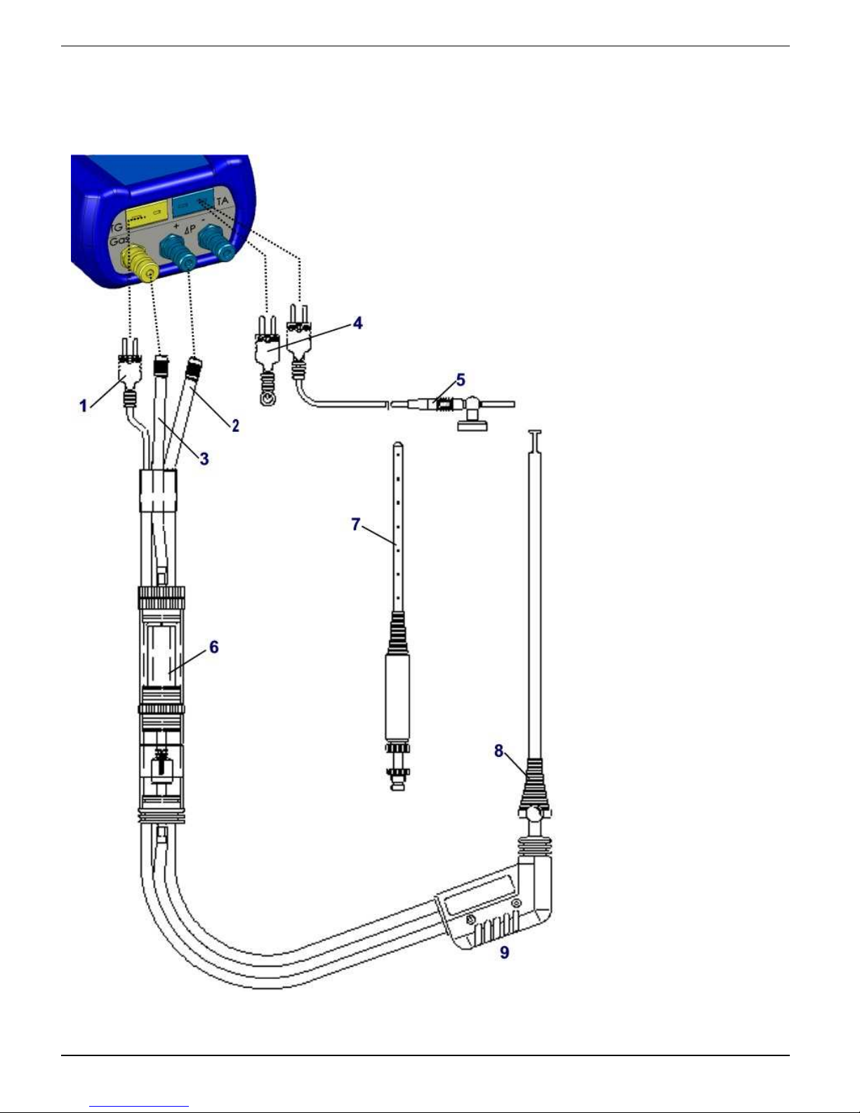
6.1 Connection diagram
1
Plug for flue gas
temperature (yellow)
2
Draft hose
3
Hose for measurement gas
4
(Combustion) air
temperature sensor
blue
5
(Combustion) air
temperature sensor
with 2.5 m line and
magnet retainer
6
Measurement gas
treatment (see extra
sheet)
7
Multi-hole probe
8
Adjustable cone
9
Flue gas probe with
draft for measurements according to
1. BImSchV
Fig.2: Connection diagram

SYSTRONIK Program start
EUROLYZER® ST / STe 17
1
Power supply unit
100-240 V/5060 Hz
2
MicroSD memory
card
3
IR printer interface
(not shown)
4
USB data interface
5
RESET button
Fig.3: Connection diagram (interface side)
7 Program start
Switch on the EUROLYZER® ST/STe by placing a finger on the button with the ON/OFF symbol. Activation of the device may take up to
5 seconds after longer periods of inoperation since an activation trigger is generated in so-called "sleep mode". If the device does not
switch on after a further attempt, the battery may be empty. Please
use only the device-specific charger / the charger shipped with the
device.
1. Switch on device:
First start screen "FLUEGAS" is shown:

Measuring programs and Settings menu SYSTRONIK
18 EUROLYZER® ST / STe
2. Use the scroll panel: Slightly move the finger over the scroll
panel to select the desired program.
3. Confirm selected measuring program:
Calibration phase is started.
8 Measuring programs and Settings menu
8.1 "Flue gas measurement" program
Start the "FLUEGAS" program.
(menu colour: green)
After a cold start the calibration phase takes 30 seconds.
After calibration the last fuel used is selected by default and dis-
played for confirmation.

SYSTRONIK Measuring programs and Settings menu
EUROLYZER® ST / STe 19
Button Function
Select other fuels
Confirm selected fuel for measurement.
Switch off device.
Repeat calibration (10 sec.)
Select and confirm required fuel.
Button Function
Scroll through measured value display line by line.
Display start menu.
Cancel measuring program. Return to start menu.
Switch off device.

Measuring programs and Settings menu SYSTRONIK
20 EUROLYZER® ST / STe
Keep measured values/activate HOLD function.
As soon as the flashing HOLD symbol is displayed in the status bar,
all measured values (except draft) are held temporarily.
Switch gas pump off or back on.
When the gas pump is switched off, the pump symbol is no longer
shown in the status bar. Changes in the corresponding measured
gas values cannot be ruled out, e.g. the O2 value may change as a
result of lack of oxygen in the gas lines inside the device. If the gas
pump remains off for a longer period of time, calibration in fresh air
should be carried out before a new measurement is made.

SYSTRONIK Measuring programs and Settings menu
EUROLYZER® ST / STe 21
Print measurement record (current measured values)
Measured values which were not in HOLD mode prior to the print
command are current values or "momentary values". These values
are printed immediately upon activation of the print command.
As soon as the print command is chosen, the record is printed parallel to the measuring task ( multitasking function), i.e. the measurement mode remains active.
Print measurement record (measured values stored with HOLD)
Measured values in HOLD mode can be checked prior to printing. It
is also possible to print values recorded in HOLD mode at a later
point in time.
Measuring programs and Settings menu SYSTRONIK
22 EUROLYZER® ST / STe
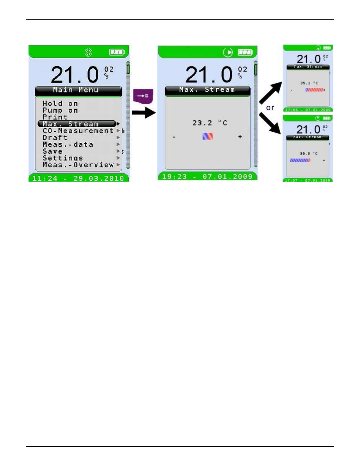
Determine the maximum stream.
Minimum temperature changes in the flue gas are sufficient to
quickly and safely determine the measuring point in the maximum
stream using the graphic trend indication.
The menu item "Max. Stream" is only available in the program
"FLUEGAS".

SYSTRONIK Measuring programs and Settings menu
EUROLYZER® ST / STe 23
Perform CO-Measurement.
Upon completion of the CO-Measurement, you can document the
measured values (EUROprinter, etc.).

Measuring programs and Settings menu SYSTRONIK
24 EUROLYZER® ST / STe
Perform draft measurement.
To determine the zero point (= initial value in relation to the ambient
air pressure), the air hose (with the blue connector) must be unplugged before each draft measurement. After this, the zero point
can be readjusted in case of a deviation from "0.00 hPa". Re-connect
the draft hose for measurement and complete the measurement.
The measured draft value can be included in the record by means of
the "HOLD" command followed by confirmation with the Apply function. Draft measurements can be repeated any number of times.
The applied draft measurement is then displayed in the list of flue
gas values and can be printed/saved.

SYSTRONIK Measuring programs and Settings menu
EUROLYZER® ST / STe 25
Enter further measured data (soot spot number, oil derivatives)
and further configuration (units, sequence of measured values).
Change units for temperature values (° C ° F).

Measuring programs and Settings menu SYSTRONIK
26 EUROLYZER® ST / STe
Change units for pressure or draft (Pa hPA –> mbar
mmWs …).
Enter smoke number (reading according to BACHARACH
scale).

SYSTRONIK Measuring programs and Settings menu
EUROLYZER® ST / STe 27
The entered smoke numbers are used exclusively for documentation
in the printed measurement record/stored measurement data.
Enter oil derivatives.
Classification of the oil derivatives is not displayed in the measurement menu. However, they can be documented in so far as they can
be printed and saved along with all other measured values.

Measuring programs and Settings menu SYSTRONIK
28 EUROLYZER® ST / STe
Enter boiler temperature.
The entered boiler temperature is handled in the same manner as
the smoke number and oil derivatives, i.e. it is used exclusively for
documentation in the printed measurement record/stored measurement data.
Change sequence of measured values (MV)
Example: Display TG value as second value.

SYSTRONIK Measuring programs and Settings menu
EUROLYZER® ST / STe 29
Configure limit value.
The required limit value can be configured within the respective
(nominal) measuring range on a user-specific basis. Values exceeding the limit value are displayed in red.

Measuring programs and Settings menu SYSTRONIK
30 EUROLYZER® ST / STe
Activate condensing mode.
In the case of measurements at condensing systems that generate
the flue gas in condensing mode, the use of the latent condensation
heat is visualised in the status line. The unit displays three drops
which uniquely identify this operating state in the upper line as long
as the flue gas temperature is below the fuel-specific dew point
Fig. 4: EST-020 cond.
In condensing mode, the efficiency Eta can be greater than 100.

SYSTRONIK Measuring programs and Settings menu
EUROLYZER® ST / STe 31
8.2 "Temperature measurement" program
Start "TEMPERATURE" program.
(menu colour: blue)
Key Function
Cancel or exit measuring program. Back to start menu.
Display main menu.
Switch off device.
Hold measured values: Activate HOLD function.

Measuring programs and Settings menu SYSTRONIK
32 EUROLYZER® ST / STe
8.3 "Pressure measurement" program
Start "PRESSURE" program.
(menu colour: yellow)
Key Function
Cancel or exit measuring program. Back to start menu.
Display main menu.
Switch off device.
Hold measured values: Activate HOLD function.

SYSTRONIK Measuring programs and Settings menu
EUROLYZER® ST / STe 33
8.4 "Settings" configuration menu
Open "SETTINGS" configuration menu.
(menu colour: purple
Button Function
Exit "Settings" configuration menu.
Scroll to select other menu item.
Display submenu.
Switch off device.
Select required settings function

Memory mode & memory structure (option) SYSTRONIK
34 EUROLYZER® ST / STe
9 Memory mode & memory structure (option)
The use of Micro-SD memory cards as system-independent storage
media ensures maximum flexibility in terms of storing and handling
the measured data. All standard Micro-SD cards (with a memory of
up to 2 GB) can be used. The card can be read without any additional software by all SD-card-enabled data processing systems
(PCs, laptops, notebooks, etc.) using a web browser. More than
1,000,000 measured values can be saved with the recommended
memory capacity of 1 GB.
Display "MEMORY" menu.
(menu colour: dark red)

SYSTRONIK Memory mode & memory structure (option)
EUROLYZER® ST / STe 35
1
Current directory (here
main folder)
2
Existing directory (represented by a right arrow)
3
Existing file (represented
by a dot)
4
Create a new folder
5
Create a new file
Button Function
Use the Clear/Escape button to go to the higher level
directory
Open the subdirectory with the Enter button.

Memory mode & memory structure (option) SYSTRONIK
36 EUROLYZER® ST / STe
Button Function
The Enter button opens a menu containing functions for
either creating a new file or displaying, printing or overwriting an existing one.
You can save measured data when you are in one of the measuring
programs. In the "Memory" menu (menu colour: dark red) you cannot
save measured data.

SYSTRONIK Memory mode & memory structure (option)
EUROLYZER® ST / STe 37
Using EUROLYZER® ST/STe as a USB storage device..
EUROLYZER® ST/STe can be used as a USB flash drive. To use
EUROLYZER® ST/STe as a USB storage device, connect the device to a PC using a USB cable.
After the PC has detected the device, EUROLYZER® ST/STe is displayed as a USB storage device by the PC. Before unplugging the
cable, you should use the "Safely Remove Hardware" function of the
PC to remove the device.
Update EUROLYZER® ST/Ste firmware.

Memory mode & memory structure (option) SYSTRONIK
38 EUROLYZER® ST / STe
Memory structure
The stored data always consists of 2 files: a text-only file with the extension .txt and an HTML file with the extension .htm. The text file
can be created on the PC using any text editor. The text file contains
the target address/a description of the measuring site. The maximum
length is 4 lines of 24 characters each. If there is no .txt file, the device can create an empty text file via "New file". The target address is
visible during file selection.
When the file is saved or overwritten, the target address is included
in the remaining device data according to the logic shown above and
can then be displayed in the device or printed.
The HTML file uses standard HTML format and can be displayed
and printed in any web browser. The memory can therefore be used
on any PC system (Windows, Linux, MAC OS, etc.).

SYSTRONIK Memory mode & memory structure (option)
EUROLYZER® ST / STe 39
9.1 How to save
It is possible to create a new directory in the current directory using
"New Dir.". The directory name has the following structure:
Directory (= folder). Number from 0…65535
It is possible to create a new file in the current folder using "New file".
The file name has the following structure:
File. Number from 0…65535
The numbers are consecutive and incremented automatically.
Limitations:
• Maximum 62 files / directories + New Dir. + New File possible
per directory.
• Maximum 4 directory levels are possible.
• File names are restricted to the "8.3" format, i.e. 8 characters for
the file name and 3 characters for the extension.
• Directory names are also limited to 8 characters.
• Only files with the extension .txt are displayed as only such files
are required.
• Special characters must not be used in the file names.
• The card is to be formatted with FAT32 or FAT16. Formatting
in the device is not possible.
• Remove the card only after switching off or before switching on in order to prevent loss of data!
D_xxxxx
F_xxxxx.txt

Battery management SYSTRONIK
40 EUROLYZER® ST / STe
• A file which has been created and saved on the card is pro-
tected against manipulation and, if manipulated, can neither be displayed by the device nor printed!
10 Battery management
10.1 Battery mode/charging mode
• Battery mode: Up to 8 hours of continuous measurement.
• Charging: External power supply unit 100-240 V~/50-60 Hz. In-
telligent charging by means of an integrated charger management system.
10.2 Charging the batteries
CAUTION
Damage to the batteries or the device caused by power supply
units that are not device-specific.
Use only the provided power supply unit for charging the batter-
ies.
1. Connect the EUROLYZER® ST/STe to the device-specific
power supply unit and the power supply unit to the mains.
2. Switch the device on and off.
The charging process of the batteries starts automatically:
45 %
Current battery capacity [%]
Button Function
Close battery menu.

SYSTRONIK Battery management
EUROLYZER® ST / STe 41
During measurements, the battery is also charged continuously
and monitored by the system.
As soon as the battery is fully charged the device switches to passive recharging mode (trickle charging).
The charge control display is no longer shown.
When recharging is finished the charger can remain connected
to the EUROLYZER® ST/STe without the battery being damaged.
Service life and capacity of the battery
The EUROLYZER® ST/STe is equipped with a powerful NiMH battery. The service life and capacity of the battery are considerably affected by the way the device is charged and used. In order to make
handling safer, the device features efficient and battery-saving
charge management suitable for all applications.
The graphical charge level indicator of the EUROLYZER® ST/STe
consisting of three elements of a battery symbol helps the user to
correctly estimate the capacity of the battery. Five different battery
states are detected.
During normal use it is recommended not to recharge the bat-
tery until it is run down completely.
The battery can be recharged at any time given that the charge
management system recognises the need to recharge the battery.
Otherwise, the charge management system will not release the battery for charging.
The service life of the NiMH battery is significantly reduced when the
device is operated at temperatures below +5 °C.
Reconditioning cycle
If the device is used outside the permitted temperature range, if the
battery is older or if incomplete charging cycles (charging/discharging) are carried out, the charge level indication may not
correspond to the actual charge level. In this case the indicator can
be corrected as follows:
1. Discharge the battery by switching on the device until it switches
off automatically.
2. Connect the EUROLYZER® ST/STe to the device-specific
power supply unit and the power supply unit to the mains.
3. Switch the device on and off.
The charging of the battery starts automatically.
Complete recharging takes approx. 4 hours, depending on the
ambient temperature.

Maintenance SYSTRONIK
42 EUROLYZER® ST / STe
The EUROLYZER® ST/STe switches off automatically when active recharging is completed.
4. Repeat the reconditioning cycle if necessary.
11 Maintenance
Gas treatment, refer to fig. 5, page 44.
Empty the condensate trap completely after each operation.
Water in the measuring device will destroy pumps and sensors.
Check the fine filter for pollution and replace as necessary.
If pump capacity is reduced, carefully replace the Teflon mem-
brane filter. Damage to the filter membrane greatly decreases or
eliminates the filter function and leads to the failure of expensive
pumps and sensors.
Make sure threaded parts are straight when positioned and
tighten them moderately. Ensure sufficient sealing by means of
O rings.
Hard-to-move/plug parts (plug-type elements and flanges): Re-
move any gas residues and grease with Vaseline.
Replacing the battery
For technical reasons, old batteries may only be replaced by the
manufacturer or an authorised service partner.
Do not short-circuit connection terminals.
To protect the environment, batteries must not be disposed of
together with the normal household waste. Return old batteries
to the point of purchase or to a collecting point.
12 Troubleshooting
Repairs may only be performed by specially trained, qualified staff.
Table 8:Troubleshooting
Problem Possible reason Repair
Device automatically
switches off.
Battery empty. Charge battery.
Battery defective.
Take device to service
centre.
O2 error message.
Service life of O2
sensor expired.
Run device without ac-
cessories in fresh air
Repeated signal
error.
Take device to service
centre.

SYSTRONIK Troubleshooting
EUROLYZER® ST / STe 43
Problem Possible reason Repair
"CO value too
high"/“CO sensor defective“
message.
CO sensor malfunction.
Run device without ac-
cessories in fresh air.
CO measuring
range exceeded.
End of service
life of sensor.
Take device in for servic-
ing.
Incorrect
measured gas
values (e.g.
measured O2
value too high,
CO2 value too
low, no CO
values displayed, etc.).
Leak in measuring system.
Check gas treatment sys-
tem for cracks and other
damage.
Check hose system for
cracks and other damage.
Check O rings of gas
treatment unit.
Check O ring of external
probe pipe.
Service message.
Device has not
been inspected
for a longer period.
Take device in for servic-
ing.
Measured gas
values are
displayed
slowly.
Filter in the gas
treatment system
is used up.
Check filter and replace, if
necessary.
Hose system
bent.
Check hose system
Gas pump polluted.
Take device to service
centre.
Flue gas temperature unstable.
Humidity in the
probe pipe.
Clean probe.
Device does
not switch on.
Battery empty. Charge battery.
Take device to service
centre.
Other malfunctions
– Send the device to the
manufacturer.

Shutting down and disposal SYSTRONIK
44 EUROLYZER® ST / STe
13 Shutting down and disposal
To protect the environment, this device must not be disposed of
together with the normal household waste. Dispose of the device according to the local conditions and directives.
This device consists of materials that can be reused by recycling
firms. The electronic inserts can be easily separated and the device
consists of recyclable materials.
If you do not have the opportunity to dispose of the used device in
accordance with environmental regulations, please contact us for
possibilities to return it.
14 Spare parts and accessories
Bild 5: Gas treatment – condensate cartridge
Part Part no.
Condensate cartridge 69411
Spare parts for condensate cartridge:
(1) Outlet piece
695 000 98
(2) O ring 18 x 3
(5) O ring 23 x 2
Kit of assorted O rings, sorted
69427
(3) Teflon membrane 23.5 mm, 10 pieces
69206
(4) Intermediate piece
695 000 97
(6) Infiltec fine filter, 5 pieces
69412
(7) Glass piston with logo
695 000 99
(8) Centre piece with cylinder pieces
695 000 96
(9) Glass piston with arrow
695 000 95
(10) Inlet piece
695 000 94

SYSTRONIK Warranty
EUROLYZER® ST / STe 45
15 Warranty
The manufacturer's warranty for this product is 24 months after the
date of purchase. This warranty shall be good in all countries in
which this device is sold by the manufacturer or its authorised dealers.
16 Copyright
The manufacturer retains the copyright to this manual. This manual
may not be reprinted, translated, copied in part or in whole without
prior written consent.
We reserve the right to technical modifications with reference to the
specifications and illustrations in this manual.
17 Customer satisfaction
Customer satisfaction is our prime objective. Please get in touch with
us if you have any questions, suggestions or problems concerning
your product.
18 Addresses
The addresses of our worldwide representations and offices can be
found on the Internet at www.systronik.com
Appendix SYSTRONIK
46 EUROLYZER® ST / STe
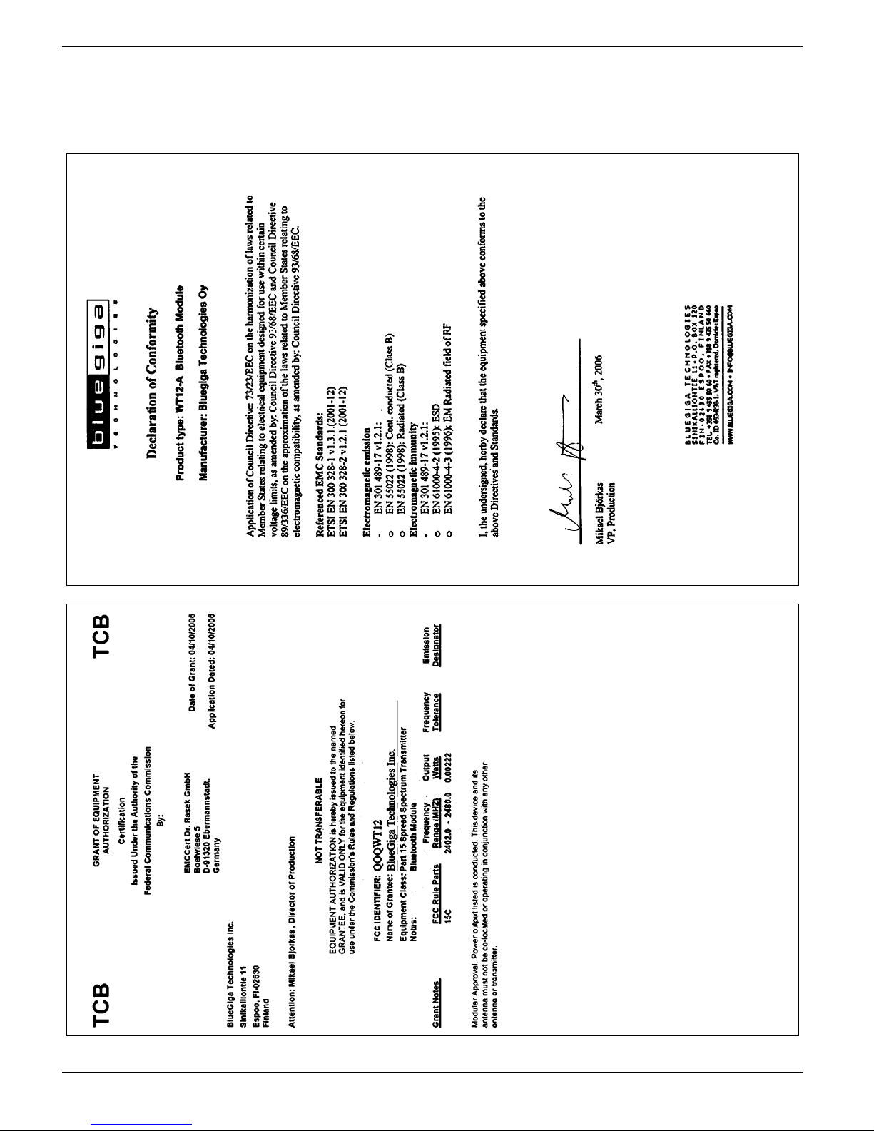
19 Appendix
19.1 Bluetooth Declaration of Conformity

SYSTRONIK Appendix
EUROLYZER® ST / STe 47
19.2 DIN EN 50379 Certificate
 Loading...