

Systron Donner 100A Service manual


OPERATION
&
MAINTENANCE
HANDBOOK
CONCORD INSTRUMENT DIVISION
Syrtron
Drtve
r
10
Tel: (415) 676-5000 TWX: 910-481-9479 . Cable: SYSTRONOONNER
Concord, Caltforn~a 94518 . U.S.A.
MODEL
700A
PULSE GENERATOR
Part
Number
37000
-
690
WARRANTY
Systron-Donner instruments are warranted during a period of one year from date of shipment to
original purchaser to be free from defects in material and workmanship. This warranty does not apply
to vacuum tubes, except as these are warranted by tube manufacturers. The liability of Seller under
this warranty is limited to replacing or repairing any instrument or component thereof which is returned
by Buyer, at his expense, during such period and which has not been subjected to misuse, neglect.
improper installation, repair, alteration, or accident. Seller shall have the right to final determination as
a
to the existence and cause of
damages. This warranty is in lieu of any other warranty, expressed, implied, or statutory; and no
agreement extending or modifying it will be binding upon Seller unless in writing and signed by
authorized officer.
defect. In no event shall Seller
RECEIVING INSPECTION
Every Systron-Donner instrument is carefully inspected and is in perfect working order at the time of
shipment. Each instrument should be checked as soon as received. If the unit is damaged in any way, or
a
fails to operate,
Whenever a Systron-Donner instrument requires service, the nearest Systron-Donner representative
should be contacted; all representatives will provide immediate
necessary.
Please specify both model and serial number in all correspondence concerning Systron-Donner instruments. Address all inquiries on operation or applications to your nearest sales representative; or, Sales
Manager, Concord Instrument Division, Systron-Donner Corporation,
California
claim should immediately be filed with the transportation company.
94518.
be
liable for collateral or consequential
a
duly
service or arrange factory returns when
10
Systron Drive, Concord.

-
MODEL
S
OOA
-
-
+
-
-
Thr
forrnanc~
ing
of
a
variety
state
circuits
It)rmanc~,
positive
and
variable
cither
chronous
single
are
for
anrl
pulsr
singly
cycIt=
supplied
pulse
Datapulsr,
pulse
over
eating,
drblay
gen~rakorrlrsigned
of
reduce
in
a
cunvenic~nhlv
nrgative
rate,
width,
broarl
or
dou\~It.pulsr
trlggerinc.
for
svstem
in
Model
lOOA
Modrl
el~ctronic
conlplpxity
outputs
amplitude,
ranges.
and
either
Two
applicationand
the
sin~lc
Pulse
Generator
100Aia
equipmrnt.
compact
operation,
internal,
pulse
an
for
and
provide
package.
dplirrr
synchronizing
anti
Front
rnorle.
L
rlplay
economical
general
Unfqur.,
natts
are
panel
synchronous or
external,
to
provide
high
purpose
versatile
Simultaneous
into
513
continuously
controls
or
trigger
a
reference
per-
test-
all
solicl
per-
ohms,
select
asyn-
manual
outputs
iii

MODEL 1 WA
TITLE PAGE
FRONTISPIECE
TABLE OF CONTENTS
LlST OF SCHEMATICS
LlST OF
l
LLUSTRATIONS
LlST OF TABLES
SECTION
I
SPEC1 FICATIONS
TABLE OF CONTENTS
PAGE
i
iii
v
vi
vi
vii
Repetition Rate
External Trigger
Manual Cycling
Gated Operation
Trigger Outputs
Pulse Mode
Pulse Delay
Pulse Width
Main Pulse Output
Rise and Fall Time
Jitter
Waveform Aberration
Output Protection
Output Mixing
Operating Temperature
Power Required
Physical Characteristics
Accessories Available
SECTION
SECTION
I1 OPERATION
2.1
2.2
2.3
2.4
2.5
Ill
THEORY OF OPERATION
General Information
Controls and Connectors
Functional Verification
Operating Instructions
Definitions
3.1 General Description
3.2 Circuit Description
MODEL 100A
SECTION
SECTION V
Drawing Number
Figure Number
IV
MAINTENANCE
4.1 Preventive Maintenance
4.2 Parts Removal
4.3 Troubleshooting
4.4 Calibration
PARTS LlST
5.1 Abbreviations and Symbols
5.2 Repetition Rate Switch Assembly
5.3
5.4 Pulse Width Switch Assembly
5.5 Front Panel Assembly
5.6 Back Panel Assembly
5.7 Main Circuit Board Assembly
Pulse Delay Switch Assembly
LlST OF SCHEMATICS
Description
Block Diagram
Schematic - Model 100A Pulse Generator
Schematic
LlST OF
-
Model 100A Pulse Generator
-
Power Supply
l
LLUSTRATIONS
Title
PAGE
1
OOA
Model
Model
Front Panel
Model
Back Panel
Networks for Transistor Load
Output Decoupling Circuits
Reverse Voltage Protection
Output Mixing
Output Pulse Characteristics
Waveform Diagrams
Repetition Rate Oscillator
Trigger Multivibrator
External Trigger Amplifier
Accessories
100A Controls and Connectors
l00A Controls and Connectors
Figure Number
Title
Delay
Multivibrator
Output Drivers
Parts Location - Schematic
Top View
Bottom View - Model lOOA
LIST
OF
and
-
Model 100A
TABLES
Amplifiers
37000
MODEL
-
152
lOOA
PAGE
3-11
3-14
4
-5
4
-8
4
-9
Table Number
4-1
Title
Troubleshooting
4
-6
vii
MODEL
l00A
SECTION
I
SPECIFICATIONS
1.1
1
hertz to 10 megahertz in eight decade ranges for either
0.
single or double pulse operation. Effective rates to 20 mega-
hertz may be set up in the double pulse mode.
1.2
operates at
minimum duration of 20 nanoseconds, or 50 hertz to
10 megahertz from
and level controls provide triggering at any point on the
input waveform more than 0.25 volts and less than 5 volts
above or below the average dc level. Input impedance is
greater than 2. 5k ohms. The maximum transient amplitude
which may be applied safely is
1.3
pulse pushbutton provides one cycle of output (single or
double pulse
Repetition Rate
Repetition rate is continuously variable from
External Trigger
The external trigger input is ac coupled, and
0 to 10 megahertz from f0.25 volt pulses with a
1
volt rms sine maves.
+5
volts.
Slope polarity
Manual Cycling
In the single pulse mode, actuating the single
mode).
1.4
ous), synchronously gated, or asynchronously gated. Signal
levels more positive than
the outputs in either gated mode. The maximum level which
may
Gated Operation
The gating mode is selected as nongated (continu-
t2
volts are required to enable
hc
applied safely is 10 volts.
MODEL
1.4.
1
1 OOA SPECIFICATIONS
Synchronous Gating
this mode and is turned on for the duration of an applied gate
pulse.
and synchronized to the gate signal.
1.4.2 Asynchronous Gating
and the rate oscillator operates continuously.
outputs and the reference trigger begin with the first cycle
(internally or externally triggered) after
occurs and stop when the gate pulse subsides. The advanced
trigger is not gated and occurs at the oscillator repetition
rate.
1.5
1.5. 1 Advanced Trigger
minimum amplitude of 1.
is typically 15 nanoseconds in duration.
ternally triggered operations only, the advance trigger
occurs approximately
fore the reference trigger.
1.5.2 Reference Trigger
minimum amplitude of 2.0 volts from a 50 ohm source, and
is typically 15 nanoseconds in duration. When triggered
from an external source, the reference trigger occurs
approximately 30 nanoseconds after the external trigger.
The repetition rate oscillator
Both main outputs and both trigger
The pulse delay circuit is gated in
Trigger
The advanced trigger is a positive pulse with a
The
Outputs
7
volts from a 50 ohm source, and
10% of the repetition rate period be-
reference trigger is a positive pulse with a
i: normally off in
output. are gated
thi: mode,
the
gate pul~e
Available on in-
Main
pul: e
1.6
the pulse mode switch.
Pulse Mode
Single or double pul~e operation is zelected
hy
SPECIFICATIONS MODEL lOOA
1.6. 1 Single Pulse
at the end of the delay period.
1. 6.2 Double Pulse
outputs, the first approximately 40 nanoseconds after the
reference trigger, and the
the pulse delay controls.
One pulse per cycle occurs in the main outputs
Two identical pulses per cycle occur in the main
second at a time determined by
Pulse Delay
40 nanoseconds with respect to the reference trigger, or
60 nanoseconds with respect to an external trigger,
maximum of 10 seconds in seven decade ranges with a
100:l multiplier.
pulse period up to a repetition rate of 1 megahertz, decreasing to
The reference trigger is counted down when the delay is
greater than the pulse period, with stable countdown ratios
greater than 100: 1 possible; the advance trigger is not
counted down.
1.8
50%
the
35 nanoseconds (40 nanoseconds maximum) to 10 seconds in
seven decade ranges with a
duty cycle is at least
Pulse delay is continuously variable from
up to a
Delay is variable over at least
50% above 4 megahertz and 30% at 10 megahertz.
70% of the
Pulse Width
Pulse width is continuously variable (measured at
point of the leading and trailing edges) from typically
100:l multiplier. The maximum
60% and is typically 7070.
Main
Pulse Output
0. 5 to 10 volts into 50 ohms with simultaneous positive and
negative dc coupled outputs (baselines are at ground). The
source impedance decreases with amplitude and is approxi-
mately 50 ohms at amplitudes less than
Pulse amplitude is continuously variable from
5
volts.
MODEL IOOA SPECIFICATIONS
1.10
time is typically less than
~naximurn) with the outputs terminated in 50 ohm resistive
loads.
1.11
than
decade on the width and delay ranges with more than
10: 1 coverage).
1.12
aberration are typically less than
k70/0)
connected 50 ohm terminations).
1.13
nation of front panel control settings and will withstand
short circuits to ground of any duration.
is not rated for operation into loads at other than ground
potential.
Rise and Fall Time
Rise time is less than 5 nanoseconds, and fall
7
nanoseconds (10 nanoseconds
Jitter
Repetition rate, delay, and width jitter are less
0.
15%
(typically 0. 1%) on each range (within the highest
Waveform Aberration
Overshoot, preshoot, ringing, and top slope
f5%
(with a maximum
at amplitudes greater than 3 volts (with properly
Output Protection
Output stages will not be damaged by any combi-
The instrument
of
1.14
negligible loss of amplitude. Same or opposite polarity
outputs may be resistor mixed with a resultant loss of
amplitude. Outputs may not be directly coupled together.
Output Mixing
Same polarity outputs may be diode mixed with a
SPECIFICATIONS
1.15 Operating Temperature
MODEL
lOOA
The instrument is designed for operation in
ambient temperatures of 0
1.16
and 50-400 hertz
regulated against line and load changes.
1.17
Dilnensions are 3-112 inches high by 8-112 inches wide and
11 inches deep.
tached line cord and
front panel are brushed aluminum with black etched mark-
ings and trim. The russet brown top, bottom, and side
panels are removable. A tilt-up bracket is provided.
Instruments
unit) or Type 1006 (dual unit) Rack Mounting Sets.
1.18
1. 18. 1 Type 1005 Rack Mounting Set
19 inch wide by 3-112 inch high rack panel, offset to either
side of center.
Power Required
Approximately 15 watts at 105-125/210-230 volts
ac is required.
Physical Characteristics
Instrument weight is approximately 8 pounds.
Each instrument is furnished with an at-
NEMA
may
he
rack mounted by Type 1005 (single
Accessories Available (Figure
This set mounts a single instrument in a standard
0
to 50° C (32O to 122O
All power supplies are
3-prong plug. The cabinet and
F).
1-1)
1.18.2
19 inch wide by 3- 112 inch high rack panel.
1.18.3
termination of 50 ohm coaxial cables for fast-rise pulse
outputs.
Type 1006 Rack Mounting Set
a
This set mounts two instruments in
Type
2003A 50 ohm Termination
This specially designed load provides proper
standard
MODEL
1.
18.4
trigger output (advanced or reference) for applications
requiring a negative synchronous trigger.
lOOA SPECIFICATIONS
2
Type
The 2 101 transformer inverts the poeitive
101 Inverting Transformer
1. 18.5
outputs with approximately 1 volt loss of amplitude.
1.
18.
6
pulse rise and fall times.
1.
18.
7
supplied with each instrument. Additional handbooks are
available at a slight additional charge.
Type 2302 Mixing Unit
The mixing unit combines two same polarity
Type 240 1 Variable Integrator.
This accessory provides a means of varying
Instruction Manual
One operation and maintenance handbook is

Figure
1-1.
Model
lOOA
Accessories.
MODEL l00A
SECTION
II
OPERATION
General Information
CAUTION
The outputs are designed for 50 ohm
resistive loads. An inductive load or
active circuit connected directly to an
output may damage the instrument.
2.4
Refer to paragraph
Instructions) for non-standard load
connection and output mixing
tion.
Pulse amplitude, width, delay, and repetition
rate are continuously variable over broad ranges, and pro-
vide an infinite variety of pulse parameter combinations to
satisfy many test requirements.
operation,
flexible external gating and triggering, and countdoun
capabilities extend the
operating convenience is gained through 1000: 1
control and 100: 1 range multiplication of pulse width and
delay. Available accessories provide variable rise and
fall times, reference trigger inversion, low loss output
mixing and minimum distortion load termination.
simultaneous positive and negative outputs,
instrunlent's versatility. Extra
(Operating
inforrna-
Single or double pulse
vernler
Gating capabilities consist of synchronous, asyn-
chronous, and coincidence gating. The output pulse train is
synchronized to the leading edge of an externally applied
gate waveform in the synchronous mode.
nous mode, the output pulse train begins with the first
advance trigger after the gate pulse occurs and continues
until the gate pulse subsides; the output is quiescently off
between gate pulses while the
provides advance trigger outputs.
gated in both modes while the advance trigger is gated in
the synchronous mode only. Coincidence gating is achieved
by application of both a gate signal and an external trigger
pulse so that output pulses occur only when the two are coincident.
rate oscillator continuously
The reference trigger is
In the asynchro-
MODEL lOOA OPERATION
Frequency division by synchronous countdown is
obtained from either internal or external triggering when
the delay is set greater than the trigger period and the output pulse rate is a subharmonic of the trigger rate. The
reference trigger occurs at the subharmonic rate in either
case while the advanced trigger occurs at the oscillator rate
for internal triggering and is turned off for external triggering.
2.2
2.2.1
transformer primary and lights the pilot lamp when the
switch is turned
2.2.2
either internal or external triggering and the repetition rate
range for internally triggered operation. The smaller vernier knob provides continuously variable control of all
ranges. There are eight decade ranges and the instrument
is set to the rate indicated on the front panel when the
nie r is fully clockwise.
ment to be triggered manually for one cycle of output by the
SINGLE PULSE pushbutton.
permit the instrument to be triggered from an external
source by either a positive or negative going waveform.
(t)
the
instrument for operation from an external source.
Controls
Power Switch
The
Repetition Rate
The REPETITION RATE rotary switch selects
The SINGLE PULSE position permits the instru-
The EXT TRIG
The TRIGGERING LEVEL control determines
or
(-)
amplitude of a signal that will trigger the
and
POWER
ON.
Connectors (Figure
switch connects ac power to the
SLOPE
(t)
and
2-1)
(-)
positions
ver-
A BNC connector is provided for the external
TRIGGER INPUT.


Figure
2-1
b.
Model
IOOA
Controls
and
Connectors.
I
I
I
I
I
OPERATION MODEL lOOA
2.2.
3
Pulse Delay
seven decade ranges and the smaller vernier knob provides
The PULSE DELAY rotary switch selects one of
continuously variable control of each range.
The instrument is set to the delay indicated on the front panel when
the vernier is fully clockwise.
The ranges are multiplied
by 100 when the vernier knob is pulled out.
NOTE:
limited to a single range step.
by vernier control causes pulse distortion.
may become unstable because recovery time
Vernier control of pulse delay and width should be
Too much range reduction
Also the outputs
is
longer for
higher ranges.
2.2.4 Pulse Width
The PULSE WIDTH rotary switch selects one of
seven decade ranges and the smaller vernier knob provides
continuously variable control for each range. The instrument is set to the width indicated on the front panel when
the vernier is fully clockwise.
The ranges are multiplied
by 100 when the vernier knob is pulled out.
2.2.5 Amplitude
The POSITIVE and NEGATIVE pulse AMPLITUDE
knobs provide continuously variable amplitude control of the
simultaneously occurring main outputs. The baseline for
both outputs is at ground potential.
nectors couple the main outputs to external loads.
The POS OUTPUT and
NEG
OUTPUT
BNC
con-
The
GRD jack provides access to the instrument ground for test
connections.
2.2.
6
Gate Mode
The main outputs are continuous when the GATE
MODE switch is in the NON-GATED position but are interrupted and occur in gated bursts, as controlled by an ex-
ternally applied gate signal, when the
switch is in either the
SYNC or the ASYNC position.
MODEL IOOA
In the SYNC position, the repetition rate oscillator
is disabled and the main output pulses occur only during the
pulse interval of an applied gate signal.
pulse of a gated burst is synchronized to the leading edge of
the gate pulse and both trigger outputs are gated.
rate oscillator is disabled in the ASYNC position, and on in-
ternally triggered operations the advance trigger is available
as a clock pulse.
begin with the first rate oscillator pulse after the start of
gate pulse and continue until the gate pulse subsides, for
either internal or external triggering.
The pulse delay circuit, rather than the repetition
Main output and reference trigger pulses
The fir st main
0PERP.TION
a
ENABLING GATE INPUT BNC connector.
2.2.7 Pulse Mode
the
PULSE
per cycle occurs at the outputs,
trigger for
~ulses occur when the switch
is delayed approximately 30
trigger, and the second is delayed for
by the delay controls.
2.2.8 Trigger Output
the ADVANCE and REFERENCE trigger outputs to external
instruments.
2.2.9 Power Input
3-prong plug is attached to the back of the instrument.
connects the power transformer primaries for operation
from either a 115 or a 230 volt ac input.
cartridge type fuse mounted on the back
The external gate signal is connected to the
Single or double pulse operation is selected by
MODE switch. In the
a
period set by the delay controls.
The TRIGGER OUTPUT BNC connectors couple
A 6-foot, 3-wire ac line cord with a
The
115/230 selector switch on the back panel
Overload protection is provided by a
SGL
delayed from the reference
is
in the DBL ~o~ition. the first
nano~econds from the reference
position, one pul~e
Two
identical
a
period determined
NEMA
112
ampere
pancl.
OPERATION
MODEL
1
OOA
2.3
of the instrument and an introduction to the
2.3.
1
Functional Verification
The following procedure provides a brief check
CAU
TION
The instrument is designed for resistive
loads only. Reactive loads connected
directly to the output will produce pulse
distortion. Inductive loads may damage
the instrument. Refer to paragraphs
2.4.4
load connections.
Equipment (or equivalent) Required
a.
b.
through
A
general purpose oscilloscope of at least
15 megahertz
NOTE:
adequate for the basic tests outlined here but
a sampling oscilloscope is needed for a full
range check to verify specifications.
axial attenuators for the main pulse and
trigger outputs may also be required because
many sampling oscilloscopes are limited to
inputs below
A 50
2
watts dissipation such as a Datapulse
2003A
2.4.6
The general purpose oscilloscope is
ohm coaxial termination capable of
Power Termination.
for nonstandard
bandpass with triggered sweep.
250
millivolts.
control^.
Co-
NOTE.
for most combinations of control settings
but should be used with care because pulse
output power approaches
duty cycle waveforms at full amplitude.
A
c.
nectors capable of
A
d.
of
A
one watt termination ie adequate
2
watts for high
50
ohm coaxial termination with
1
/
2
watt dissipation.
general purpose signal generator capable
2
volts into
500
ohms (the square wave
BNC
con-
MODEL
IOOA OPERATION
amplitude calibrator of many oscilloscopes
may be adequate).
2.3.2
e. Three
(3-4
feet long) 50 ohm coaxial cables
with BNC connectors, and one BNC Tee connector.
Test Connections and Settings
CAU
TION
Check the position of the 1151230 volt
slide switch on the back panel for
agreement with the line voltage before
connecting the power cord.
Connect the instrument to a suitable power
a.
source.
Connect a 50 ohm coaxial cable from the POS
b.
OUTPUT to the oscilloscope input, and terminate the cable at the oscilloscope using the
(2
50 ohm
watt) coaxial termination and the
BNC Tee connector.
Connect a 50 ohm cable from the REFERENCE
c.
TRIGGER OUTPUT to the oscilloscope trigger
input, and terminate the cable in 50 ohms at
the oscilloscope using the
112 watt termi-
nation.
d.
Set the instrument controls as follows:
Control Setting
POWER switch OFF
REPETITION RATE
range 1.0 MHz
REPETITION RATE
vernier midrange
PULSE DELAY range
1. OpS
PULSE DELAY vernier midrange
PULSE WIDTH range 1.
OpS
PULSE WIDTH vernier fully clockwise
OPERATION
MODEL
POSITIVE AMPLITUDE 5V
NEGATIVE AMPLITUDE 5V
GATE MODE switch NON-GATED
PULSE MODE switch SGL
lOOA
3.
Set the oscilloscope sweep speed to
e.
and the vertical sensitivity to 2V/CM.
3
Main Pulse Output
a. Turn the POWER switch ON. Note that the
a
pilot lamp goes on, and
rectangular pulse
(approximately 5 volts high and 1 microsecond wide with a flat top and near vertical
leading and trailing edges) appears on the
oscilloscope trace.
b. Turn the POSITIVE AMPLITUDE control in
both directions and verify that the amplitude
3
decreases to
volts and increases to 10 volts
uniformly without any noticeable effect on
waveshape.
5
volt position.
the
Return the amplitude control to
c. Disconnect the coaxial cable from the POS
OUTPUT and reconnect the cable to the NEG
OUTPUT.
Note that the negative output looks
like the positive output inverted.
Repeat step
d.
(b)
for the NEGATIVE AMPLI-
TUDE control. Reconnect the POS OUTPUT
to the oscilloscope input.
e. Turn the PULSE WIDTH vernier counter-
clockwise.
the
control and decreases smoothly. Turn
Note that the pulse width follows
the vernier to the fully clockwise position.
0. 2pS/CM
i.
Turn the PULSE DELAY vernier in both
tlirections
control moving
rlght.
po
sltion.
and
Kt,turn
note that the pulse follows the
snloothly to the left and to the
the vernier to the minimum
MODEL lOOA
OPERATION
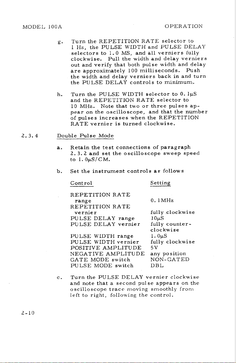
Turn the REPETITION RATE selector to
g.
1 Hz, the PULSE WIDTH and PULSE DELAY
selectors to 1.0 MS, and all verniers fully
clockwise. Pull the width and delay verniers
out and verify that both pulse width and delay
are approximately 100 milliseconds. Push
the width and delay verniers back in and turn
the PULSE DELAY controls to minimum.
h.
Turn the PULSE WIDTH selector to
and the REPETITION RATE selector to
10 MHz.
pear on the oscilloscope, and that the number
of pulses increases when the REPETITION
RATE vernier is turned clockwise.
Double Pulse Mode
a. Retain the test connections of paragraph
2.3.2 and set the oscilloscope sweep speed
to I.
Set the instrument controls
b.
Control Setting
REPETITION RATE
range
REPETITION RATE
vernier
PULSE DELAY range
PULSE DELAY vernier
PULSE WIDTH range
PULSE WIDTH vernier
POSITIVE AMPLITUDE
NEGATIVE AMPLITUDE
GATE MODE switch
PULSE MODE switch
Note that two or three pulses ap-
OpS/CM.
a? follows
fully clockwise
1
ops
fully counterclockwise
ops
1.
fully clockwise
5v
any position
NON-GATED
DBL
0.
1pS
c. Turn the PULSE DELAY vernier clockwise
and note that a second pulse appears on the
oscilloscope trace moving smoothly from
left to right,
following the control.
OPERATION MODEL lOOA
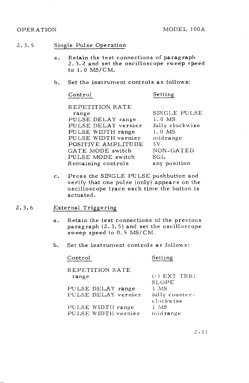
2.3.5 Single Pulse Operation
Retain the test connections of paragraph
a.
2.
3.2
and set the oscilloscope sweep speed
to 1.0 MS/CM.
Set the instrument controls as follows:
b.
2.3.
Control
Setting
REPETITION RATE
range
PULSE DELAY range
PULSE DELAY vernier
PULSE WIDTH range
PULSE WIDTH vernier
POSITIVE AMPLITUDE
GATE MODE switch
PULSE MODE switch
Remaining controls
Press the SINGLE PULSE pushbutton and
c.
SINGLE PULSE
1.0
MS
fully clockwise
MS
1.0
midrange
5
v
NON-GATED
SGL
any position
verify that one pulse (only) appears on the
oscilloscope trace each time the button is
actuated.
6
External Triggering
Retain the test connections of the previous
a.
paragraph
(2.
3.5) and set the oscillo?cope
sweep speed to 0.5 MS/CM.
b. Set the instrument controls as follows:
Control
Setting
REPETITION RATE
(i
)
EXT
range
TRIG;
SLOPE
1
PULSE DELAY range
MS
PULSE DELAY vernier lully counter-
c
lockwise
PULSE WIDTII range
I
MS
PU1,SE U IDTH vernier nildranjie
L40DE1, l0OA OPERATION
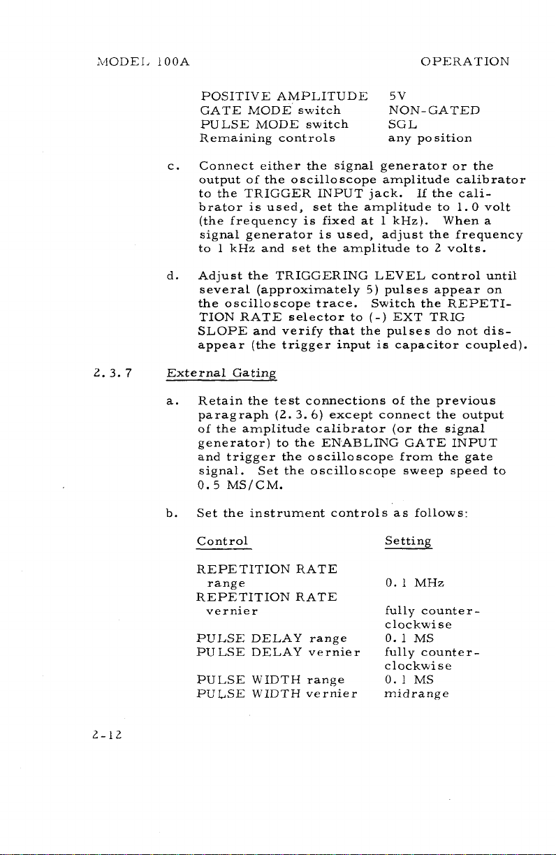
POSITIVE AMPLITUDE
GATE MODE switch NON-GATED
PULSE MODE switch SGL
Remaining controls any position
c. Connect either the signal generator or the
output of the oscilloscope amplitude calibrator
to the TRIGGER INPUT jack. If the calibrator is used, set the amplitude to 1.
(the frequency is fixed at 1 kHz). When a
signal generator is used, adjust the frequency
to
1
kHz and set the amplitude to 2 volts.
d. Adjust the TRIGGERING LEVEL control until
several (approximately 5) pulses appear on
the oscilloscope trace. Switch the REPETI-
TION RATE selector to
SLOPE and verify that the pulses do not disappear (the trigger input is capacitor coupled).
2.3.7 External Gating
a. Retain the test connections of the previous
paragraph
of the amplitude calibrator (or the signal
generator) to the ENABLING GATE INPUT
and trigger the oscilloscope from the gate
signal.
0.5
Set the oscilloscope sweep speed to
MS/CM.
5V
(-)
EXT TRIG
(2.
3.6) except connect the output
0
volt
b. Set the instrument controls as follows:
Control
REPETITION RATE
range
REPETITION RATE
vernier
PULSE
PULSE DELAY vernier
PULSE WIDTH range
PULSE WIDTH vernier
DELAY range
Setting
0.1 MHz
fully counter-
clockwise
0.1
MS
fully counter
clockwise
0.
I
MS
midrange
-
OPERATION
MODEL
lOOA
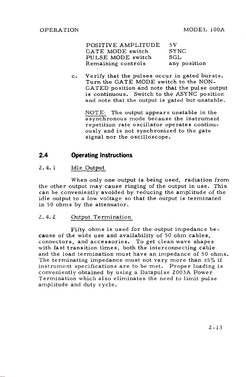
POSITIVE AMPLITUDE
GATE MODE switch
PULSE MODE switch SGL
Remaining controls any position
Verify that the pulses occur in gated bursts.
c.
Turn the GATE MODE switch to the
GATED position and note that the pulse output
is continuous.
and note that the output is gated but unstable.
NOTE:
asynchronous mode because the instrument
repetition rate oscillator operates continu-
ously and is not synchronized to the gate
signal nor the oscilloscope.
2.4
2.4.
the other output may cause
can be conveniently avoided by reducing the amplitude of the
idle output to a low voltage so that the output is terminated
in 50 ohms by the attenuator.
2.4.2
Operating Instructions
1
Idle Output
When only one output
Output Termination
The output appears unstable in the
Switch to the ASYNC position
is
ringing of the output in use. This
being used, radiation from
5V
SYNC
NON-
Fifty ohms is used for the output impedance because of the wide use and availability of 50 ohm cables,
connectors, and accessories. To get clean wave shapes
with fast transition times, both the interconnecting cable
and the load termination must have an impedance of 50 ohms.
The terminating impedance must not vary more than
instrument specifications are to be met. Proper loading is
conveniently obtained by using a Datapulse
Termination which also eliminates the need to limit pulse
amplitude and duty cycle.
2003A Power
k50/0 if
MODEL 100A
OPERATION
Output Cabling
When the pulse generator is connected to a load
that is several feet away, clean waveforms with low dis-
tortion are maintained by using a 50 ohm coaxial cable terminated in 50 ohms at the load rather than at the instrument.
Terminating at the pulse generator, using clip leads, or
using coaxial cable with the wrong characteristic impedance
will have the same pulse distorting effect as terminating in
the wrong impedance.
2.4.4 Nonlinear Loads
Operating directly into nonlinear devices
~uch as
transistors and diodes that exhibit high impedance in one direction and low impedance in the other causes waveform distortion. This can be prevented by terminating the pulse generator in a network that reflects uniform loading in both directions. Two methods for driving the base of a transistor,
or operating into a diode (the base-emitter junction of a
transistor resembles a diode) are illustrated in Figure 2-2.
In the resistor coupled network, transistor
QL is biased off
between pulses and is turned on during the pulse interval;
while in the capacitor coupled circuit,
QL is quiescently on
and is turned off by the applied pulse.
R1, R2, and Rj and capaci-
tor
C1
depend primarily on the transistor characteristics in
both circuits.
Values for resistors
R1
is calculated from the equations given in
the figure to provide proper termination for the pulse generator (50 ohms) and prevent ringing.
C2, in the capacitor
coupled network, depends on pulse width and repetition rate,
and is determined by the given equations. For a PNP tran-
sistor, the polarity of the input pulse, the applied voltage,
In
and the diode are reversed.
both networks, load mismatch
and waveform distortion are more pronounced at fast rise
and fall times.
2.4.5 Output
An
Decoupling
emitter follower may be used to decouple the
output from a nonlinear load when the passive networks of
Figure 2-2 are unsuitable. The circuits of Figure 2-3 are
useful, for example, when more power
i~
required than can
 Loading...