

Systium Technologies 555 Assembly Manual
SySTIUM
®
TECHNOLOGIES
Assembly Guide
Model 555

SySTIUM® TECHNOLOGIES MotherBoard ReadyTM System • MODEL 555
Radio Frequency Interference Notice (USA)
This equipment has been tested and found to comply with the limits for a Class B digital device, pursuant to Part 15 of
the FCC Rules. These limits are designed to provide reasonable protection against harmful interference in a residential
installation. This equipment generates, uses, and can radiate radio frequency energy and, if not installed and used in
accordance with the instructions, may cause harmful interference to radio communications. However, there is no
guarantee that interference will not occur in a particular installation. If this equipment does cause harmful interference to
radio or television reception, which can be determined by turning the equipment off and on, the user is encouraged to
try to correct the interference by one or more of the following measures:
• Reorient or relocate the receiving antenna.
• Increase the separation between the equipment and the receiver.
• Connect the equipment into an outlet on a circuit different from that to which the receiver is connected.
• Consult the dealer or an experienced radio/TV technician for help.
Any changes or modifications not expressly approved by the grantee of this device could void the user’s authority to
operate the equipment. The customer is responsible for ensuring compliance of the modified product.
Only peripherals (computer input/output devices, terminals, printers, etc.) that comply with FCC class B limits may be
attached to this computer product. Operation with noncompliant peripherals is likely to result in interference to radio and
TV reception.
All cables used to connect to peripherals must be shielded and grounded. Operation with cables, connected to
peripherals that are not shielded and grounded may result in interference to radio and TV reception.
Manufacturer: SySTIUM® Technologies, LLC
New Hope, MN 55428
763-537-3600
Contact: Customer Support
NOTE
If a Class A device is installed within this system; then the system is to be considered a Class A system. In this
configuration, operation of this equipment in a residential area is likely to cause harmful interference.
Radio Frequency Interference Notice (CDN)
This Class B digital apparatus complies with Canadian ICES-003:2004
Cet appareil numérique de Ia classe B est conforme a Ia norme NMB-003:2004 du Canada.
Declaration of the Manufacturer or Importer
This system is compliant with Low Voltage Directive 2006/95/EC using the standard EN 609501:2006/A11:2009/A1:2010/A12:2011, (IEC 60950-1:2005 (2nd Edition); Am 1:2009).
This system is compliant with EU directive 2004/108/EC using the standards EN55022:2010 and EN55024:2010.
Disclaimer Statement
SySTIUM® Technologies makes no warranty of any kind with regard to this material, including, but not limited to, the
implied warranties of merchantability and fitness for a particular purpose. SySTIUM® Technologies assumes no
responsibility for any errors that may appear in this document. SySTIUM® Technologies makes no commitment to
update nor to keep current the information contained in this document. No part of this document may be copied or
reproduced in any form or by any means without prior written consent of SySTIUM® Technologies.
Third-party brands and trademarks are the property of their respective owners.
SySTIUM® TECHNOLOGIES MotherBoard ReadySM System • MODEL 555
ASSEMBLY GUIDE
Assembly Safety Instructions
Assembly of a computer system using the Systium
Model 555 enclosure t shall be done only by technically
qualified personnel. Follow the instructions in the
document “Model 555 Maintaining Regulatory
Compliance” to meet and maintain the safety and
product regulatory compliance of this product when
assembling a computer system using this product.
WARNINGS
Read and adhere to all of these instructions and
instructions supplied with this assembly. Failure
to follow these instructions will result in voiding
the products regulatory compliance statements.
The procedures in this document assume familiarity
with the general terminology associated with personal
computers and with the safety practices and regulatory
compliance required for using and modifying electronic
equipment.
WARNINGS
TO PREVENT ACCESS TO HIGH
ELECTRICAL ENERGY PARTS, DO NOT
REMOVE THE COVERS WHILE THE
SYSTEM IS POWERED ON!
Do not open the power supply. The power supply
in this computer contains no user-serviceable
parts. To avoid personal injury or damage to
your equipment, refer repair or replacement of
the power supply to qualified technical personnel
only. All other areas and components of this
computer are considered user-accessible.
CAUTIONS
Electrostatic discharge (ESD) can damage disk
drives, add-in cards, and other components.
Follow the procedures described in this chapter
only at an ESD workstation. If such a station is
not available, you can provide some ESD
protection by wearing an anti-static wrist strap
and attaching it to a metal part of the chassis.
Add-in cards can be extremely sensitive to ESD
and always require careful handling. After
removing the card from its protective wrapper or
from the computer, place the card flat on a
grounded, static-free surface, component side
up. Use a conductive foam pad (f available, but
not the board wrapper Do not slide the board
over any surface.
For proper cooling and airflow, always close the chassis
before turning on the computer system. Operating the
computer system without the chassis closed can
damage system parts.
Before You Begin
1. Be sure to follow each procedure in the correct
order.
2. Set up an equipment log to record the computer’s
model and serial numbers, all installed options,
and other information about the computer. This
information must be saved as a record of the
product’s configuration and compliance with the
allowable configuration options.
3. We recommend that you use an anti-static wrist
strap and a conductive foam pad when working
on the computer.
4. You will need a Phillips (#1 and #2 bits)
screwdriver and Needle Nose Pliers.
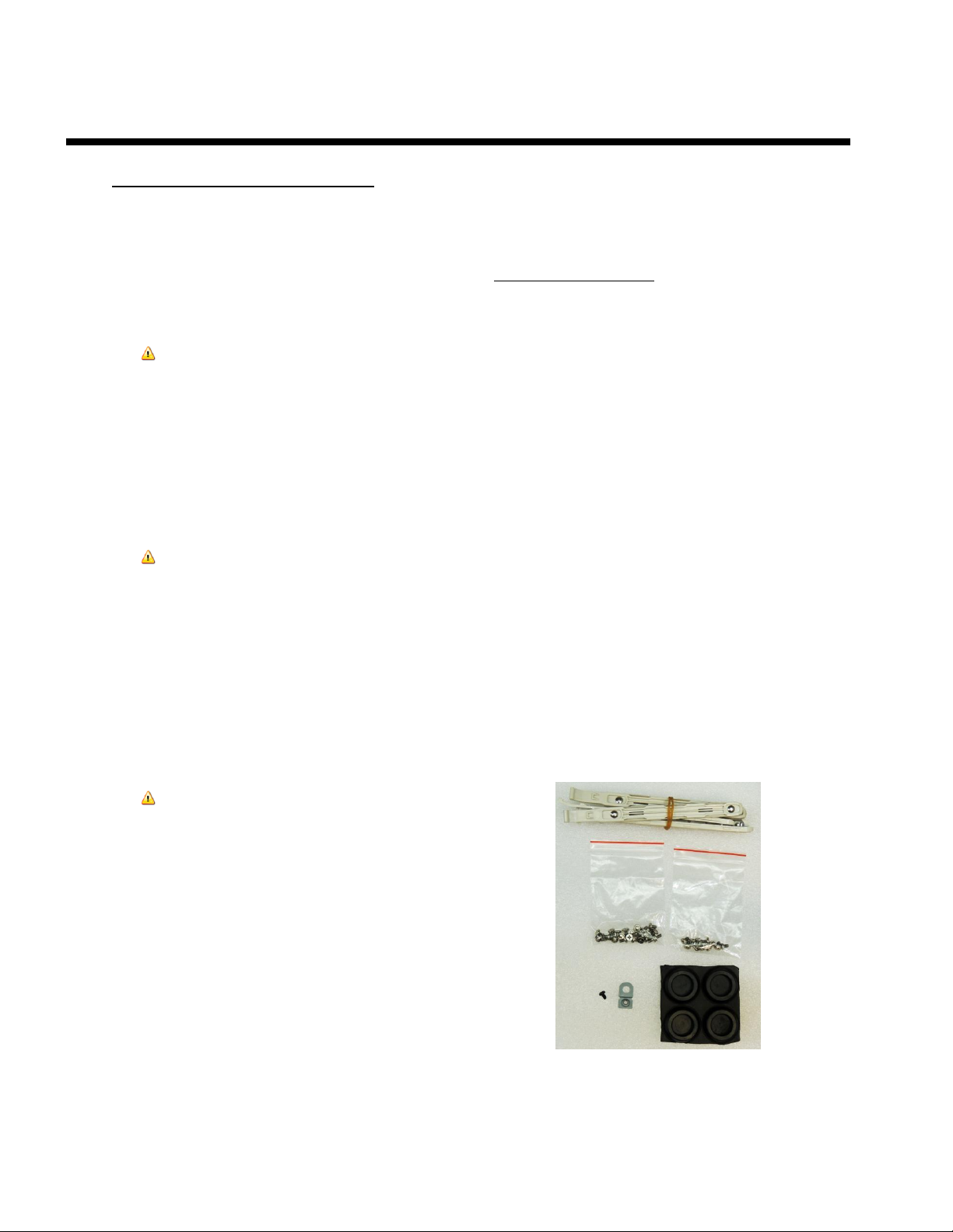
NOTE
The integration kit provides screws for the
following as shown in Figure 1:
• Six 3.5 peripheral mounting slides
• One lock tab and its associated .25” 6-32
Screw
• Eleven 6-32 Phillips Screws
• Six M3 Phillips screw
• Four Chassis Feet
FIGURE 1
Copyright © 2013, SySTIUM® Technologies, LLC
PN: 91609-00 Rev01
 Loading...