

Series Matrix X
M3216AX
M3216XX
M3208AX
M1608AX
Installation
Manual
2850-00002
SYS E
M

SYSEM

Page 12
Specifications
..........................................................
Page 11
Junction Boxes
................................................................
Page 10
LON® Network Cable Lengths
................................................
Page 10
LON® Network Cables
........................................................
Page 9
Repeater
........................................................................
Page 9
Termination
....................................................................
Page 8
Bus Topology
...................................................................
Page 8
Selection of network Topology
................................................
Page 8
LON® Installation
........................................................
Page 7
Video standard selection
...................................................
Page 7
Rear panel indicator
............................................................
Page 7
Front panel indicator
...........................................................
Page 7
LED indicators
.............................................................
Page 6
First time start
............................................................
Page 6
Other connections
...........................................................
Page 6
Remote Sites
..................................................................
Page 6
Video input- and output expansion using the M3216XX
.......................
Page 6
Video input- and output expansion
............................................
Page 5
Video output expansion
........................................................
Page 5
Video input expansion
.........................................................
Page 4
Video expansion
.............................................................
Page 4
Video connections
.......................................................
Page 4
LON® connection
.............................................................
Page 3
Mains fuse
....................................................................
Page 3
Mains installation
............................................................
Page 3
Unpacking the unit
..........................................................
Page 3
Installation
................................................................
Page 2
Trademarks
...................................................................
Page 2
Approvals
.....................................................................
Page 2
Compatibility
.................................................................
Page 2
Validity
........................................................................
Page 2
Introduction
..............................................................
SYSEM

Introduction
The Series Matrix X consists of a number of video matrix units controlled via LONWORKS®:
Ÿ M3216AX: 32 video inputs / 16 video outputs with loop facilities on both video
inputs and outputs for easy expansion.
Ÿ M3208AX: 32 video inputs / 8 video outputs with loop facilities on both video inputs
and outputs for easy expansion.
Ÿ M1608AX: 16 video inputs / 8 video outputs.
Ÿ M3216XX: Used as an cost saving expansion unit in combination with the M3216AX
only. In an expanded system not all matrix units have cameras or monitors
connected. At these location(s) the M3216XX unit is used which consequently is
equipped with video loop connectors only; no BNC- video connectors are available.
By interconnecting several Matrix X units the number of video inputs and/or outputs is
increased.
The video input terminations can be programmed to 75
Ω or high impedance (Hi-Z).
All settings are selected remotely using the S111SX Node Manager - no settings are
possible on the unit itself, except selection of video standard; either PAL/CCIR (factory
default) or NTSC/RS-170.
Daily operation is carried out via the keyboards Series K111xX.
Validity
This manual cover the Matrix X types M3216AX, M3216XX, M3208AX and M1608AX,
serial number MxxxxxX-0100, where “xxxxx” represents the typenumber, or higher.
The described Remote Site functionality is available with the Node Manager V.2.0 or higher.
Compatibility
The Matrix X is compatible with any SYSTEM X component.
Any device outputting a standard 1 V
pp
video signal may be connected to the video inputs.
Approvals
All electronic equipment can emit, or be sensitive to, induced electromagnetic noise, which
can be conducted the connected wires or transmitted as electromagnetic fields.
Electromagnetic noise can cause malfunction or damage to the equipment.
The Matrix X is -certified and approved in accordance with the EU-directives regarding
Electromagnetic Compatibility, the EMC-directive, and Low Voltage safety, the LVD-directive
with respect to the EN 50081-1 (EMC, emission), the EN 50130-4 (EMC, immunity) and the
EN 60950 (LVD, safety) standards.
WARNING: To fulfil the above regulations make sure to carefully follow
the installation instructions in this manual.
Trademarks
Echelon®, LON® and LONWORKS® are trademarks of Echelon Corporation registered in the
United States of America and other countries.
SYSEM

Installation
Carefully follow the instructions in order not to cause mal-function, damage to the
equipment or humans. Incorrect installation will void the warranty and repairs will
consequently be invoiced according to current scale charges.
All connections are shown on the figures at the fold-out page at the back of this manual.
After all connections have been made installation is completed by switching on the mains
supply. Finally should the Service Pin be activated, however, prior to pressing the Service Pin
make sure the S111SX Node Manager is running and connected to the LON
®
network.
Please note, that it is of outmost importance to keep track of the order in which the various
System X units are activated e.g. by carefully noting the exact time the Service Pin is
activated. This information is crucial when identification and configuration of each unit is
carried out later using the S111SX Node Manager.
Unpacking the unit
Check that the carton box contains the following items:
Ÿ A Matrix X of the correct type (M3216AX, M3216XX, M3208AX or M1608AX).
Ÿ A connector/mounting kit, consisting of:
2 pcs. rack mounting ears.
2 pcs. 9-pin D-SUB connectors.
1 pc. LON
®
connector and cable clamp.
Various screws and washers.
Ÿ Installation manual (this manual).
Carefully check for any sign of damage. Any such damage or parts missing should be
reported to your supplier prior to installation.
Mains installation
The Matrix X must be used with a 3-wire mains connection (2W+PE @ min. 0,75 mm2,
PE=yellow/green, N=blue).
The unit adapts itself to the actual mains voltage; no adjustments are needed.
WARNING: If permanently connected to mains, a readily accessible
disconnect device (mains switch) shall be incorporated in the building
installation wiring.
If pluggable connection to mains has been made, the socket-outlet shall
be present near the equipment and shall be easily accessible.
Mains connection requires installation by an instructed person.
The unit is designed for continous operation.
Mains fuse
A replaceable fuse is located at the power supply board.
Ÿ Designator: F1
Ÿ Rating: F2,5AH, 250V
SYSEM
LON® connection
All SYSTEM X components (nodes) are connected together in a common LONWORKS
®
communication network.
Refer to the drawings at the fold-out page at the end of this manual. Connection is polarity
insensitive. A detailed description of cabling, network topology, temination etc is included in
the LON
®
Installation section located later in this instruction.
Note: If you have no previous experience with LON® , study the LON® Installation section
carefully!
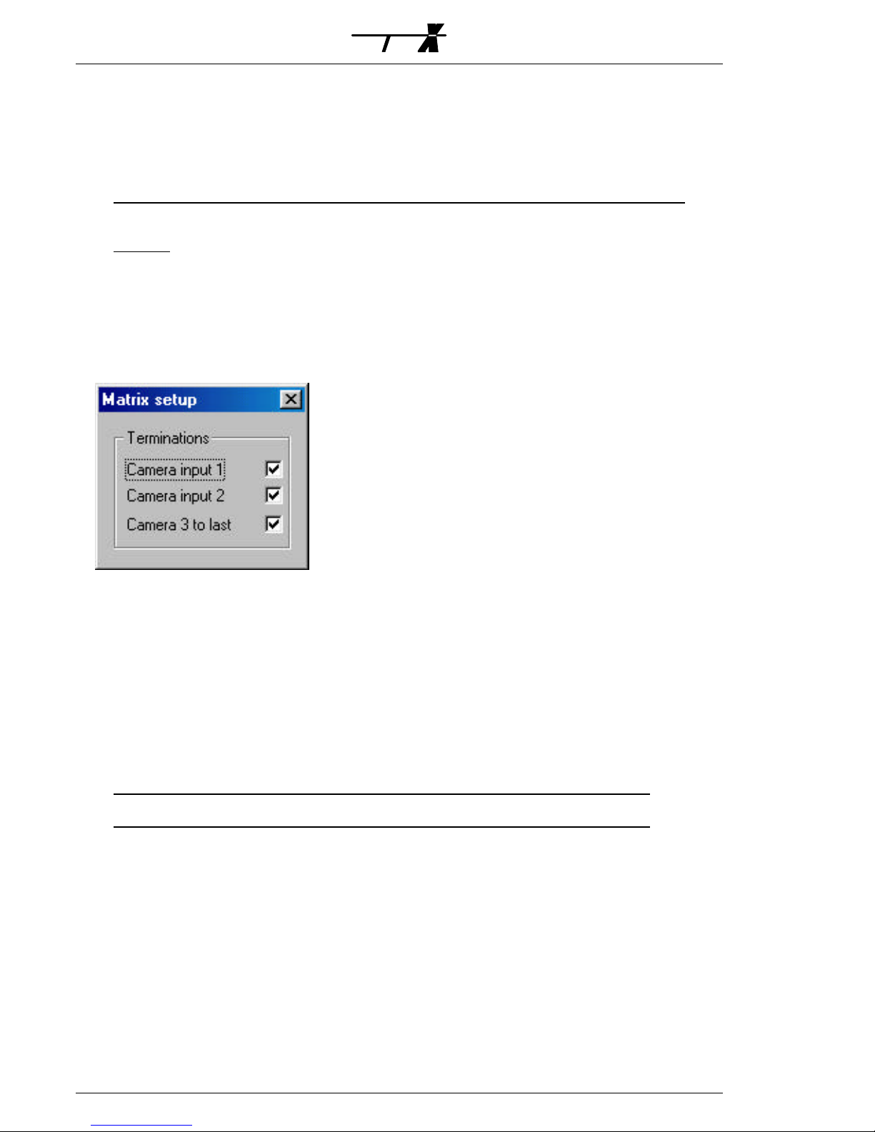
Video connections
Refer to the drawings at the fold-out page at the end of this manual.
The video input terminations can be programmed to 75
Ω or high impedance (Hi-Z) using
the S111SX Node Manager as shown below:
The relevant video signal standard; either PAL/CCIR (factory default) or NTSC/RS-170, is
selected by means of internal jumper(s); refer to the Video standard selection section.
Video expansion
Expansion of video inputs and/or outputs is carried out by combining several Matrix X units
and looping the video connections. For optimum video performance inter-connect the units
as shown on the fold-out page drawings.
On the M3216AX/XX and the M3208AX video looping is established by inter-connecting
the video loop connectors with the special XLOOP cables, available in three different lengths;
350 mm, 675 mm and 1100 mm. Refer to the fold-out page drawings for instructions and
selection of the appropriate cable.
Note: XLOOP cables are not included and should be ordered seperately from your supplier.
The M3216XX is a unit designed as a video expansion unit to be used in combination with
the M3216AX only. It is equipped with video loop connectors only; no BNC- video connectors
are available.
The M1608AX is not equipped with video loop connectors. Video expansion must therefore
be made by inter-connecting the BNC video inputs/outputs using BNC dual straight
“Y”-adaptors as described below.
SYSEM

Video input expansion
Ÿ M3216AX/3208AX: Connect a XLOOP cable from the LOOP MON connector on the
first unit to the neighbouring LOOP MON connector on the unit above or below.
Further units are interconnected in the same way.
Connect cameras 1-32 to the video inputs on first unit, cameras 33-65 to the second
unit a.s.o. Video input terminations should be activated on all units; i.e. set to 75
Ω.
Connect the monitors to the video outputs on one of the units; when three or more
units are used to the unit in the middle for optimum performance.
Ÿ M1608AX: Connect each video output on the first unit with the corresponding
output on the second unit using BNC dual straight “Y”-adaptors. Further units are
interconnected in the same way.
Connect cameras 1-16 to the video inputs on first unit, cameras 17-32 to the second
unit a.s.o. Video input terminations should be activated on all units; i.e. set to 75
Ω.
Connect the monitors to the unused “leg” on the “Y”-adaptors fitted on the first or
last unit.
Video output expansion
Ÿ M3216AX: Connect a XLOOP cable from the LOOP CAM. 1-16 connector on the first
unit to the neighbouring LOOP CAM. 1-16 connector on the next unit.
Furthermore connect a XLOOP cable from the LOOP CAM. 17-32 connector on the
first unit to the neighbouring LOOP CAM. 17-32 connector on the next unit. For
further expansion with more monitor outputs, i.e. more than 32, additional units are
added in the same way.
Connect cameras 1-32 to the video inputs on first unit only, and activate the video
input terminations, i.e. set them to 75
Ω, on the last unit only.
Connect the monitors 1-16 to the video outputs on the first unit and monitors 17-32
to the second unit a.s.o.
Ÿ M3208AX: Connect a XLOOP cable from the LOOP CAM. 1-16 connector on the first
unit to the neighbouring LOOP CAM. 1-16 connector on the next unit.
Furthermore connect a XLOOP cable from the LOOP CAM. 17-32 connector on the
first unit to the neighbouring LOOP CAM. 17-32 connector on the next unit. For
further expansion with more monitor outputs, i.e. more than 16, additional units are
added in the same way.
Connect cameras 1-32 to the video inputs on first unit only, and activate the video
input terminations, i.e. set them to 75
Ω, on the last unit only.
Connect the monitors 1-8 to the video outputs on the first unit and monitors 9-16
to the second unit a.s.o.
Note: M3216AX units and M3208AX units can freely be combined. By combining e.g. a
M3216AX and a M3208AX unit a 24 video output matrix is made.
By combining two M3216AX’s and one M3208AX unit a matrix with 40 video outputs is formed.
Ÿ M1608AX: Fit BNC dual straight “Y”-adaptors on the video inputs on the first unit
and connect the cameras to one of the “legs”. Connect the other leg to the
corresponding video inputs on the second unit. Further units are interconnected in
the same way.
Activate the video input terminations, i.e. set them to 75
Ω, on the last unit only.
Connect the monitors 1-8 to the video outputs on the first unit, monitors 9-16 to
the second unit a.s.o..
SYSEM

Video input- and output expansion
Simply follow and combine the instructions given in the above two sections.
For optimum video performance connect the cameras, monitors and XLOOP cables as
shown on the fold-out page drawings.
Note that the LOOP MON connectors should be interconnected with XLOOP cables on units
with the same monitor range setting; e.g. all monitor 1-16 units should have their LOOP
MON connectors interconnected, all monitor 17-32 units should have their LOOP MON
connectors interconnected a.s.o. Do not make any LOOP MON connections from e.g. a
monitor 1-16 unit to a monitor 17-32 unit. Refer to the example of a 96 input / 48 output
matrix on the fold-out page.
Video input- and output expansion using the M3216XX
The M3216XX is identical to the M3216AX,
except for not being equipped with
BNC-connectors for video inputs and outputs. In
an expanded system not all matrix units have
cameras or monitors connected and the
M3216XX can consequently be used at these
positions as shown on the figure.
Remote Sites
It is possible to interconnect two, or more,
individual matrix systems, so-called Sites, each consisting of a single or multiple Matrix X units
(i.e. an expanded matrix system).
This will enable display and control of cameras connected to one site on the monitors
connected to another site.
Using several, distributed matrix systems; i.e. Sites, will often reduce and simplify the
cabling needed, campared to a single, central matrix.
Also the Ernitec SYSTEM 1000M matrix can be used as a remote system, meaning that
from a System X it is possible to view and operate cameras connected to the remote
SYSTEM 1000M. The I151SX-REMOTE protocol conversion box must be used as interface
between the LON
®
Network and a serial port on the SYSTEM 1000M.
In general, a number of video links must be established between the Sites. In other words,
a number of monitor outputs on one site are connected to a corresponding number of video
inputs on another site.
The minimum number of video links is one only; however, the more video links available,
the more different Remote Site cameras may be displayed at the locat site monitors
simultaneously. Obviously, there is no idea in having more video links from the Remote Site
than local site monitors. In other words, if the local site has eight monitor outputs there is no
need to establish more than eight video links from the remote site.
One Site may be connected to and surveilled from several other sites and by establishing
two sets of video links between two sites, one in each direction, each site can view cameras
from the other site.
It is not
possible to “daisy-chain” sites; i.e. view remote cameras connected to a third site
via a second site.
Other connections
The 9-pin DSUB connectors on the front and the rear of the matrix are reserved for internal
use and for future applications.
SYSEM
RS232 / RS485
LOOP CAM. 1-16
LOOP CAM. 1-16
2 6
4 8
135
7
10 141218
16 20
22 26
LOOP CAM. 17-32
243028 32
11
9 13
15 19
17
LOOP CAM. 17-32
23
21 25
27 31
29
LOOP MON.
2 6
4 8
10 14
12
LON
16
LOOP MON.
1
3 7511
9 13
15
M3216AX
115VAC/230VAC
RS232 / RS485
LOOP CAM. 1-16
LOOP CAM. 1-16
2 6
4 8
135
7
10 141218
16 20
22 26
LOOP CAM. 17-32
243028 32
11
9 13
15 19
17
LOOP CAM. 17-32
23
21 25
27 31
29
LOOP MON.
2 6
4 8
10 14
12
LON
16
LOOP MON.
1
3 7511
9 13
15
M3216AX
115VAC/230VAC
1-16
33-64
65-96
1-32
RS232 / RS485
LOOP CAM. 1-16
LOOP CAM. 1-16
2 6
4 8
135
7
10 141218
16 20
22 26
LOOP CAM. 17-32
243028 32
11
9 13
15 19
17
LOOP CAM. 17-32
23
21 25
27 31
29
LOOP MON.
2 6
4 8
10 14
12
LON
16
LOOP MON.
1
3 7511
9 13
15
M3216AX
115VAC/230VAC
17-32
RS232 / RS485
LOOP CAM. 1-16
LOOP CAM. 1-16
2 6
4 8
135
7
10 141218
16 20
22 26
LOOP CAM. 17-32
243028 32
11
9 13
15 19
17
LOOP CAM. 17-32
23
21 25
27 31
29
LOOP MON.
2 6
4 8
10 14
12
LON
16
LOOP MON.
1
3 7511
9 13
15
M3216AX
115VAC/230VAC
RS232 / RS485
LOOP CAM. 1-16
LOOP CAM. 1-16 LOOP CAM. 17-32
LOOP CAM. 17-32
LOOP MON.
LON
LOOP MON.
M3216XX
115VAC/230VAC
M3216XX
RS232 / RS485
LOOP CAM. 1-16
LOOP CAM. 1-16 LOOP CAM. 17-32
LOOP CAM. 17-32
LOOP MON.
LON
LOOP MON.
M3216XX
115VAC/230VAC
M3216XX

First time start
After all connections have been made installation is completed by switching on the mains
supply.
Make sure the S111SX Node Manager software is running and the PC-interface is
connected to the LON
®
network.
Activate the Service Pin using a small screw-driver or equivalent, refer to the fold-out page
drawing for exact location of the Service Pin.
Please note, that it is of outmost
importance to keep track of the order in which the
various System X units are activated e.g. by carefully noting the exact time the Service Pin is
activated. This information is crucial when identification and configuration of each unit is
carried out later using the S111SX Node Manager.
Note: Strictly follow the above instructions to avoid possible configuration problems.
The Service Pin may be activated later also if reconfiguration of the network is needed,
however, always make sure the S111SX Node Manager software is on-line prior to pressing
the Service Pin.
LED indicators
A green LED is placed at the front and an yellow LED at the rear panel.
Front panel indicator
The green LED indicates the status of the matrix:
Ÿ Steadily flashing once every second: Normal operation.
Ÿ Constantly on or off: Fault situation; disconnect from mains supply and
re-connect again.
Ÿ Flashing erractic: Download of new settings in progress.
Rear panel indicator
The yellow LED indicates the LON
®
network status:
Ÿ Off indicates normal operation; the unit is configured and running.
Ÿ Flashing and on indicates that the unit isn’t configured; run the S111SX
Node Manager and press the Service Pin.
Note: The LON® LED flashes shortly when the Service Pin is activated - this is not a fault
condition.
Video standard selection
By enabling a two-pole pinheader; i.e. shorting the two terminals with a “jumper”, located
on the main board the NTSC/RS-170 video standard is selected. The M3216AX features two
main PCB’s each having a pinheader. Top PCB is handling video outputs 9-16, bottom PCB
video outputs 1-8.
Factory default setting is PAL/CCIR; i.e. no jumper installed. Installing/removal of the jumper
must be followed by a matrix re-boot.
Refer to the fold-out page drawing for exact location of the pinheader.
SYSEM

LON® Installation
Note: If you have no previous experience with LON® installation, study this section carefully!
All SYSTEM X components (nodes) are connected together in a common LONWORKS
®
communication network.
The network is polarity insensitive and therefore either of the two twisted pair wires can be
connected to either of the LON
®
connectors on the SYSTEM X components.
Due to the risk of cross-talk/interference, it is recommended not to run LON
®
Network
cables close to high voltage cable, or cables carrying video signals.
Note: In countries where the CE approval is mandatory, LON® cables with an overall screen must
be used in order to comply with EMC/EMI standard EN 50130-4. The cable screen should be
connected to the cable clamp next to the LON
®
connector.
Selection of network Topology
In a free topology network, there are no demands as to how the cables are routed
between the nodes. It can be point-to-point, bus, star, tree, or a mixture.
Free Topology
Termination
When using free topology, the maximum cable length in one segment is approx. 500
meters, and is calculated adding together all cables used. The maximum number of nodes in
one segment is 64. If more that 500 meters, or more than 64 nodes, is required, two or
more network segments can be made, using a repeater between each segment.
Bus Topology
In a bus topology network, all nodes are connected on a bus. Cable stubs can be used to
connect the individual nodes to the bus, as long as the length of the stub is maximum 3
meters.
The advantage of bus topology, is that the cable length can be longer than when using free
topology. This can be useful e.g. when making network connection to remote PTZ cameras.
Bus Topology
Termination Termination
The maximum number of nodes on one bus is 64. Maximum length of the network bus
depends on the type of cable used. If more nodes, and/or longer cable length, is required,
two or more network segments can be made, using a repeater between each segment.
SYSEM

Termination
Each network segment require termination for
proper data transmission performance. The type of
termination varies depending on whether Free
topology or Bus topology is used.
In a free topology network segment, only one
termination is required and may be placed anywhere
on the network. The termination resistor should be a
52
Ω, 1/4W type.
In a bus topology networksegment, two
terminations are required, one at each end of the bus. The termination resistors should each
be a 105
Ω, 1/4W type.
Termination resistors, which are included with the SYSTEM X keyboard, are easily fitted
using the LON
®
connectors on the SYSTEM X units as shown on the figure.
Repeater
If the maximum numbers of nodes (max. 64) or total cable distance are exceeded, a
repeater can be added to interconnect two or more network segments.
A repeater can also be used to convert from a free topology network to a bus topology
network. This can be useful when e.g. making network connection to remote PTZ cameras.
Information on suppliers of suitable repeaters and converters can be obtained from your
supplier. Note that only one Repeater should be placed in series between any two nodes in a
segment.
Bus Topology
Termination Termination
Free Topology
Termination
3-way
Repeater
Free Topology
Termination
SYSEM
LON®cable
Termination
resistor

LON® Network Cables
The following five cables/cable types have been validated by Echelon
®
, but other cables may
be used provided they have specifications similar to the ones listed below:
Anixter 4QJB2
5)
Coferro J-Y(St)Y
5)
Waschek 240208
5)
Eupen J-Y(St)Y Lg
5)
Yes0,8mm20,4AWGJ-Y(St)Y3) 2x2x0.8
Anixter 9F220154
5)
Available
0,65mm
22AWG
Level
IV
2)
cable
-
No
1,3mm
16AWG
Belden
85102
(Tefzel
jacket) or
-
No
1,3mm
16AWG
Belden 8471 (PVC jacket) or equivalent
Belden 1624
5)
Belden 1633A
5)
Belden 1668A
5)
Available0,5mm24AWGTIA/EIA 568A1) Category 5 cable
Examples
Shield
4)
Diameter
AWG
Validated Cables and Cable Types
1)
Any cable that meets the TIA/EIA 568A standard, is suitable for LON® Networks.
2)
Standard originally specified by the National Electrical Manufacturers Association (NEMA).
3)
The J-Y(St)Y cable is normally only available in Europe.
4)
In order to comply with EMC/EMI standard EN 50130-4, shielded cable must be used.
5)
With shield.
A list of cable suppliers can be found in e.g. the K111DX Keyboard X manual.
LON® Network Cable Lengths
900 meters
320/500 meters
J-Y(St)Y 2x2x0,8
1400 meters
400/500 meters
Level IV
2700 meters
500/500 meters
Belden 85102
2700 meters
400/500 meters
Belden 8471
900 meters
250/450 meters
TIA/EIA
568A Category 5
Bus Topology
Max. Total Length
Free Topology
Max. Node-to-Node/Total Length
Cable type
SYSEM

Junction Boxes
When splicing/terminating cables in the LON
®
Network installation, the following methods
are normally used:
A Pass-Thru Junction Box is used to splice two cables. No SYSTEM X nodes or connectors
are provided at a pass-thru junction box.
Pass-Thru Junction Box
LON Network
LON Network
A Stub Junction Box is used to splice two cables and provide a stub for servicing a local
SYSTEM X node.
Stub Junction Box
LON Network
LON Network
To local node
A local Loop Junction Box is used to terminate two cables, and provide a wiring loop for
servicing one, or more, local SYSTEM X nodes.
Loop Junction Box
LON Network
LON Network
Local loop
SYSEM

Specifications
EN 50081-1, EN 50130-4 / EN 60950
Approvals EMC/LVD
D=excl.
connectors.
W excl.“rack
ears”.
88,5/426/214
(19”-2HU)
132,5/426/214 (19”-3HU)Dimensions H/W/D
@ 230/115 VAC
75 mA / 150 mA
105 / 210 mA
Current consumption
Auto-selected
230/115 VAC, 50/60 Hz
Nominal Mains voltage
78 kbps FTT-10
LONWORKS
®
TP/FT Free- or Bus-topology
Comms interface
<1,5%
Luninance non-linearity
<1,0%
Differential gain
<0,8°
Differential phase
2T Pulse/Bar
<0,4%
K-rating
<6 nsec.
Chrominance delay
Weighted
<-75 dB
Noise
@ 4,43 MHz<-60 dBCrosstalk,
input-to-input
-3 dB
10 Hz - 12 MHz
Video bandwidth
For expansion.
No
Yes
Yes
Yes
Video loop out (XLOOP)
1 Vpp, 75
Ω
880
16
Video outputs (BNC)
1 Vpp, 75
Ω
16320
32
Video inputs (BNC)
Note
M1608AX
M3208AX
M3216XX
M3216AX
SYSEM
HEAD OFFICE: ERNITEC A/S , HØRKÆR 24, DK-2730 HERLEV, DENMARK
TELEPHONE: +45 44 50 33 00, TELEFAX: +45 44 50 33 33
HOMEPAGE: http://www.ernitec.com, E-MAIL: ernitec@ernitec.dk
UK OFFICE: ERNITEC UK, GERRARD HOUSE, WORTHING ROAD, EAST PRESTON, WEST SUSSEX, BN16 1AW
TELEPHONE: 01903 77 27 27, TELEFAX: 01903 77 27 07
E-MAIL: sally@ernitec-uk.co.uk
GERMAN OFFICE: ERNITEC GmbH., STORMARNRING 28, 22145 STAPELFELD
TELEPHONE: (040) 675625 0, TELEFAX: (040) 675625 25
E-MAIL: ernitec@aol.com
FRENCH OFFICE: ERNITEC FRANCE, No 29 PARC CLUB DU MILLENAIRE, 1025 RUE HENRI BECQUEREL,
34036 MONTPELLIER CEDEX 1
TELEPHONE: 04 67 15 10 15 , TELEFAX: 04 67 64 01 81
E-MAIL: ernitec@ernitec.fr
MIDDLE EAST OFFICE: ERNITEC ME, HAMRA-MAKDESI STR., YOUNIS CENTER-5th FLOOR, OFFICE NO. 503
P.O. BOX 113/5721, BEIRUT, LEBANON
TELEPHONE: +961 1 751 796, TELEFAX: +961 1 751 795
HOMEPAGE: http://www.ernitecme.com, E-MAIL: malek_kabrit@ernitecme.com

SYSEM
Mains connection
Brown=Live
Blue=Neutral
Yellow/green=Ground
115/230 VAC auto-select.
Mains connection requires
installation by an instructed person.
LON
®
cable
Cable Shield
N/C
(reserved)
RS232 / RS485
LOOP CAM. 1-16
LOOP CAM. 1-16
2 6
4
8
1
3
5
7
10 14
12
18
16 20
22 26
LOOP CAM. 17-32
24
30
28 32
11
9 13
15 19
17
LOOP CAM. 17-32
23
21 25
27 31
29
LOOP MON.
2 6
4
8
10 14
12
LON
16
LOOP MON.
1
3 7
5
11
9 13
15
M3216AX
115VAC/230VAC
1-32
(1-16)
M3216AX: 1-16
Mxx08AX: 1-8
LON
"LONWORKS
®
" service pin:
NOTE: To be activated only
when the S111SX Node
Manager is on-line.
Note exact time of activation.
"LONWORKS
®
" indication:
OFF=Configured.
ON/Flashing=Unconfigured.
Matrix X basic connections
RS232 / RS485
LOOP CAM. 1-16
LOOP CAM. 1-16
2 6
4
8
1
3
5
7
10 14
12
18
16 20
22 26
LOOP CAM. 17-32
24
30
28 32
11
9 13
15 19
17
LOOP CAM. 17-32
23
21 25
27 31
29
LOOP MON.
2 6
4
8
10 14
12
LON
16
LOOP MON.
1
3 7
5
11
9 13
15
M3216AX
115VAC/230VAC
RS232 / RS485
LOOP CAM. 1-16
LOOP CAM. 1-16
2 6
4
8
1
3
5
7
10 14
12
18
16 20
22 26
LOOP CAM. 17-32
24
30
28 32
11
9 13
15 19
17
LOOP CAM. 17-32
23
21 25
27 31
29
LOOP MON.
2 6
4
8
10 14
12
LON
16
LOOP MON.
1
3 7
5
11
9 13
15
M3216AX
115VAC/230VAC
RS232 / RS485
LOOP CAM. 1-16
LOOP CAM. 1-16
2 6
4 813
5
7
10 14
12
18
16 20
22 26
LOOP CAM. 17-32
24
30
28 32
11
9 13
15 19
17
LOOP CAM. 17-32
23
21 25
27 31
29
LOOP MON.
2 6
4 8
10 14
12
LON
16
LOOP MON.
1
3 7
5
11
9 13
15
M3216AX
115VAC/230VAC
M3216AX: 1-16
M3208AX: 1-8
33-64
65-96
1-32
75
Ω
75
Ω
RS232 / RS485
LOOP CAM. 1-16
LOOP CAM. 1-16
2 6
4
8
1
3
5
7
10 14
12
18
16 20
22 26
LOOP CAM. 17-32
24
30
28 32
11
9 13
15 19
17
LOOP CAM. 17-32
23
21 25
27 31
29
LOOP MON.
2 6
4
8
10 14
12
LON
16
LOOP MON.
1
3 7
5
11
9 13
15
M3216AX
115VAC/230VAC
RS232 / RS485
LOOP CAM. 1-16
LOOP CAM. 1-16
2 6
4
8
1
3
5
7
10 14
12
18
16 20
22 26
LOOP CAM. 17-32
24
30
28 32
11
9 13
15 19
17
LOOP CAM. 17-32
23
21 25
27 31
29
LOOP MON.
2 6
4
8
10 14
12
LON
16
LOOP MON.
1
3 7
5
11
9 13
15
M3216AX
115VAC/230VAC
RS232 / RS485
LOOP CAM. 1-16
LOOP CAM. 1-16
2 6
4
8
1
3
5
7
10 14
12
18
16 20
22 26
LOOP CAM. 17-32
24
30
28 32
11
9 13
15 19
17
LOOP CAM. 17-32
23
21 25
27 31
29
LOOP MON.
2 6
4
8
10 14
12
LON
16
LOOP MON.
1
3 7
5
11
9 13
15
M3216AX
115VAC/230VAC
M3216AX: 17-32
M3208AX: 9-16
1-32
75
Ω
Hi-Z
Hi-Z
M3216AX: 1-16
M3208AX: 1-8
M3216AX: 33-48
M3208AX: 17-24
75
Ω
Video input expansion
Video output expansion
LON
®
LON
®
LON
®
LON
®
XLOOP350XLOOP350
XLOOP350XLOOP350
C1-32, M1-16
C33-64, M1-16
C65-96, M1-16
C1-32, M1-16
C1-32, M17-32
C1-32, M33-48
*Set with the S111SX NodeManager
*
*
*
*
*
*
*
*
*
*
RS232 / RS485
2
1
10864
53 7 9
161412
11 13 15
642
1 53
8
LON
7
M1608AX
115VAC/230VAC
?A/?A
50/60 Hz
xxxx-xxxxx
Serial no.
M1608AX
M3216AX
*
*

SYSEM
Video input & output expansion
Example: 96 input / 48 output matrix
+
75
Ω
LOOP CAM. 1-16
LOOP CAM. 1-16 LOOP CAM. 17-32
LOOP CAM. 17-32
LOOP MON.
LOOP MON.
XLOOP350
LOOP CAM. 1-16
LOOP CAM. 1-16 LOOP CAM. 17-32
LOOP CAM. 17-32
LOOP MON.
LOOP MON.
LOOP CAM. 1-16
LOOP CAM. 1-16 LOOP CAM. 17-32
LOOP CAM. 17-32
LOOP MON.
LOOP MON.
LOOP CAM. 1-16
LOOP CAM. 1-16 LOOP CAM. 17-32
LOOP CAM. 17-32
LOOP MON.
LOOP MON.
LOOP CAM. 1-16
LOOP CAM. 1-16 LOOP CAM. 17-32
LOOP CAM. 17-32
LOOP MON.
LOOP MON.
LOOP CAM. 1-16
LOOP CAM. 1-16 LOOP CAM. 17-32
LOOP CAM. 17-32
LOOP MON.
LOOP MON.
LOOP CAM. 1-16
LOOP CAM. 1-16 LOOP CAM. 17-32
LOOP CAM. 17-32
LOOP MON.
LOOP MON.
LOOP CAM. 1-16
LOOP CAM. 1-16 LOOP CAM. 17-32
LOOP CAM. 17-32
LOOP MON.
LOOP MON.
LOOP CAM. 1-16
LOOP CAM. 1-16 LOOP CAM. 17-32
LOOP CAM. 17-32
LOOP MON.
LOOP MON.
M3216AX: 17-32
M3208AX: 9-16
75
Ω
75
Ω
Hi-Z
Hi-Z
Hi-Z
Hi-Z
Hi-Z
Hi-Z
1-32
33-64
65-96
XLOOP675
C1-32, M1-16
C33-64, M1-16
M3216AX: 1-16
M3208AX: 1-8
C65-96, M1-16
C1-32, M17-32
C33-64, M17-32
C65-96, M17-32
C1-32, M33-48
M3216AX: 33-48
M3208AX: 17-24
C33-64, M33-48
C65-96, M33-48
JP 12 Video Standard
Selection:
Disabled: PAL/CCIR.
Enabled: NTSC/RS-170.
Note:
Reboot after changes.
Note:
On M3216AX set on
both top and bottom PCB.
Video Standard Selection

SYSEM
RS232 / RS485
LOOP CAM. 1-16
LOOP CAM. 1-16
2 6
4 813
5
7
10 14
12
18
16 20
22 26
LOOP CAM. 17-32
24
30
28 32
11
9 13
15 19
17
LOOP CAM. 17-32
23
21 25
27 31
29
LOOP MON.
2 6
4 8
10 14
12
LON
16
LOOP MON.
1
3 7
5
11
9 13
15
M3216AX
115VAC/230VAC
RS232 / RS485
LOOP CAM. 1-16
LOOP CAM. 1-16
2 6
4
8
1
3
5
7
10 14
12
18
16 20
22 26
LOOP CAM. 17-32
24
30
28 32
11
9 13
15 19
17
LOOP CAM. 17-32
23
21 25
27 31
29
LOOP MON.
2 6
4
8
10 14
12
LON
16
LOOP MON.
1
3 7
5
11
9 13
15
M3216AX
115VAC/230VAC
1-16
33-64
65-96
1-32
RS232 / RS485
LOOP CAM. 1-16
LOOP CAM. 1-16
2 6
4
8
1
3
5
7
10 14
12
18
16 20
22 26
LOOP CAM. 17-32
24
30
28 32
11
9 13
15 19
17
LOOP CAM. 17-32
23
21 25
27 31
29
LOOP MON.
2 6
4
8
10 14
12
LON
16
LOOP MON.
1
3 7
5
11
9 13
15
M3216AX
115VAC/230VAC
17-32
RS232 / RS485
LOOP CAM. 1-16
LOOP CAM. 1-16
2 6
4 813
5
7
10 14
12
18
16 20
22 26
LOOP CAM. 17-32
24
30
28 32
11
9 13
15 19
17
LOOP CAM. 17-32
23
21 25
27 31
29
LOOP MON.
2 6
4 8
10 14
12
LON
16
LOOP MON.
1
3 7
5
11
9 13
15
M3216AX
115VAC/230VAC
RS232 / RS485
LOOP CAM. 1-16
LOOP CAM. 1-16 LOOP CAM. 17-32
LOOP CAM. 17-32
LOOP MON.
LON
LOOP MON.
M3216XX
115VAC/230VAC
M3216XX
RS232 / RS485
LOOP CAM. 1-16
LOOP CAM. 1-16 LOOP CAM. 17-32
LOOP CAM. 17-32
LOOP MON.
LON
LOOP MON.
M3216XX
115VAC/230VAC
M3216XX
Video input & output expansion using the M3216XX
LOOP CAM. 1-16
LOOP CAM. 1-16 LOOP CAM. 17-32
LOOP CAM. 17-32
LOOP MON.
LOOP MON.
LOOP CAM. 1-16
LOOP CAM. 1-16 LOOP CAM. 17-32
LOOP CAM. 17-32
LOOP MON.
LOOP MON.
LOOP CAM. 1-16
LOOP CAM. 1-16 LOOP CAM. 17-32
LOOP CAM. 17-32
LOOP MON.
LOOP MON.
LOOP CAM. 1-16
LOOP CAM. 1-16 LOOP CAM. 17-32
LOOP CAM. 17-32
LOOP MON.
LOOP MON.
LOOP CAM. 1-16
LOOP CAM. 1-16 LOOP CAM. 17-32
LOOP CAM. 17-32
LOOP MON.
LOOP MON.
LOOP CAM. 1-16
LOOP CAM. 1-16 LOOP CAM. 17-32
LOOP CAM. 17-32
LOOP MON.
LOOP MON.
LOOP CAM. 1-16
LOOP CAM. 1-16 LOOP CAM. 17-32
LOOP CAM. 17-32
LOOP MON.
LOOP MON.
LOOP CAM. 1-16
LOOP CAM. 1-16 LOOP CAM. 17-32
LOOP CAM. 17-32
LOOP MON.
LOOP MON.
LOOP CAM. 1-16
LOOP CAM. 1-16 LOOP CAM. 17-32
LOOP CAM. 17-32
LOOP MON.
LOOP MON.
17-32
1-32
33-64
65-96
1-16
33-48
M3216XX
M3216XX
M3216XX
M3216XX
Basic principle
Example: 96 input / 32 output matrix
Recommended configuation
Example: 96 input / 48 output matrix

SYSEM
RS232 / RS485
LOOP CAM. 1-16
LOOP CAM. 1-16
2 6
4
8
1
3
5
7
10 14
12
18
16 20
22 26
LOOP CAM. 17-32
24
30
28 32
11
9 13
15 19
17
LOOP CAM. 17-32
23
21 25
27 31
29
LOOP MON.
2 6
4
8
10 14
12
LON
16
LOOP MON.
1
3 7
5
11
9 13
15
M3216AX
115VAC/230VAC
Remote Sites
Remote Site with SYSTEM 1000M
Example: Cameras connected to the SYSTEM 1000M
can be viewed and PTZ-controlled from the Matrix X.
Two video links are established for simultaneous view of
two different remote cameras.
MAINS IN
N L
SELECT
MAINS
J9
Ih=63mA
F1
C51
C52
TERM
OFF
S3
ON
J7
B-B+
RS485 TX
TEST
1
J2
TERM
OFF
ON
S5
115
2
3
0
T1
L2
U20
C48
Ih=400mA
F2
L1
C49
C50
C47
FL2
FL1
D15
~+~
-
o
U1
J4
U5
SYSTEM X
0498-00069 V.0.0
PROTOCOL CONVERTER
U2
1 2 43 65 7 8
RS485 RX/TX
B+ B- TX RX GND
RS232
J5
E3
GNDLINE LINE
LON
J8
C39
C41
RESET_N
+12V
E1
U7
U4
U3 U15
U18
U6
0 32KX8
1 64KX8
J1
1
20MHz
E2
U10
TMS
1
TDI
TD0
J3
JTAG
VCC
TCK
GND
RUN LED
C
A
U16
LON SERVICE
U14
C
S4
A
RS232 / RS485
LOOP CAM. 1-16
LOOP CAM. 1-16
2 6
4 813
5
7
10 14
12
18
16 20
22 26
LOOP CAM. 17-32
24
30
28 32
11
9 13
15 19
17
LOOP CAM. 17-32
23
21 25
27 31
29
LOOP MON.
2 6
4 8
10 14
12
LON
16
LOOP MON.
1
3 7
5
11
9 13
15
M3216AX
115VAC/230VAC
01
020304
05
060708
09
10
11
12
131415
16
17
181920
21
22
23
24
25
262728
29
30
31
32
01 03 05 07
02 04 06 08
+
1
2
5 1
69
5 1
69
5 1
69
SIO 1
SIO 2
ARC-NET
ON
OFF
ON
OFF
ON
OFF
Type:
207 - 264 VAC
25 VA
45 - 60 Hz
Made in Denmark
ON
1208M
Serial Number:
1208.21-017
SERIAL PORT *1 SETUP
TYPE : RS-232
DEVICE : IEC
BAUDRATE: 19200
RETRANS : 2
RTX TIME: 0.5 SEC
PRESS (ESC) TO QUIT
5 1
69
TX RX GND
RS232
J5
RS-232-C
03
02
05
Tx
GND
Rx
7
8
31
32
E.g.
REMOTE SYSTEM SETUP REMOTE SYSTEM ID:
*1 (10=MAIN)
MAIN CONNECTED TO
SERIAL PORT: 1
PRESS (ESC) TO QUIT
I151SX-REMOTE
RS232 / RS485
LOOP CAM. 1-16
LOOP CAM. 1-16
2 6
4 813
5
7
10 14
12
18
16 20
22 26
LOOP CAM. 17-32
24
30
28 32
11
9 13
15 19
17
LOOP CAM. 17-32
23
21 25
27 31
29
LOOP MON.
2 6
4 8
10 14
12
LON
16
LOOP MON.
1
3 7
5
11
9 13
15
M3216AX
115VAC/230VAC
RS232 / RS485
LOOP CAM. 1-16
LOOP CAM. 1-16
2 6
4 813
5
7
10 14
12
18
16 20
22 26
LOOP CAM. 17-32
24
30
28 32
11
9 13
15 19
17
LOOP CAM. 17-32
23
21 25
27 31
29
LOOP MON.
2 6
4 8
10 14
12
LON
16
LOOP MON.
1
3 7
5
11
9 13
15
M3216AX
115VAC/230VAC
#1
#2
#3
Example: Cameras connected to Sites #1 and #3 can be displayed
and controlled on the Site #2 monitors.
Minimum one video link must be established from Sites #1 and #3
- the more video links present, the more different remote cameras
may be viewed simultanously on Site #2 monitors..
 Loading...