

Page 1
INSTALLATION AND MAINTENANCE INSTRUCTIONS
FOR INTERCONNECTING MULTIPLE ZONECHECK UNITS
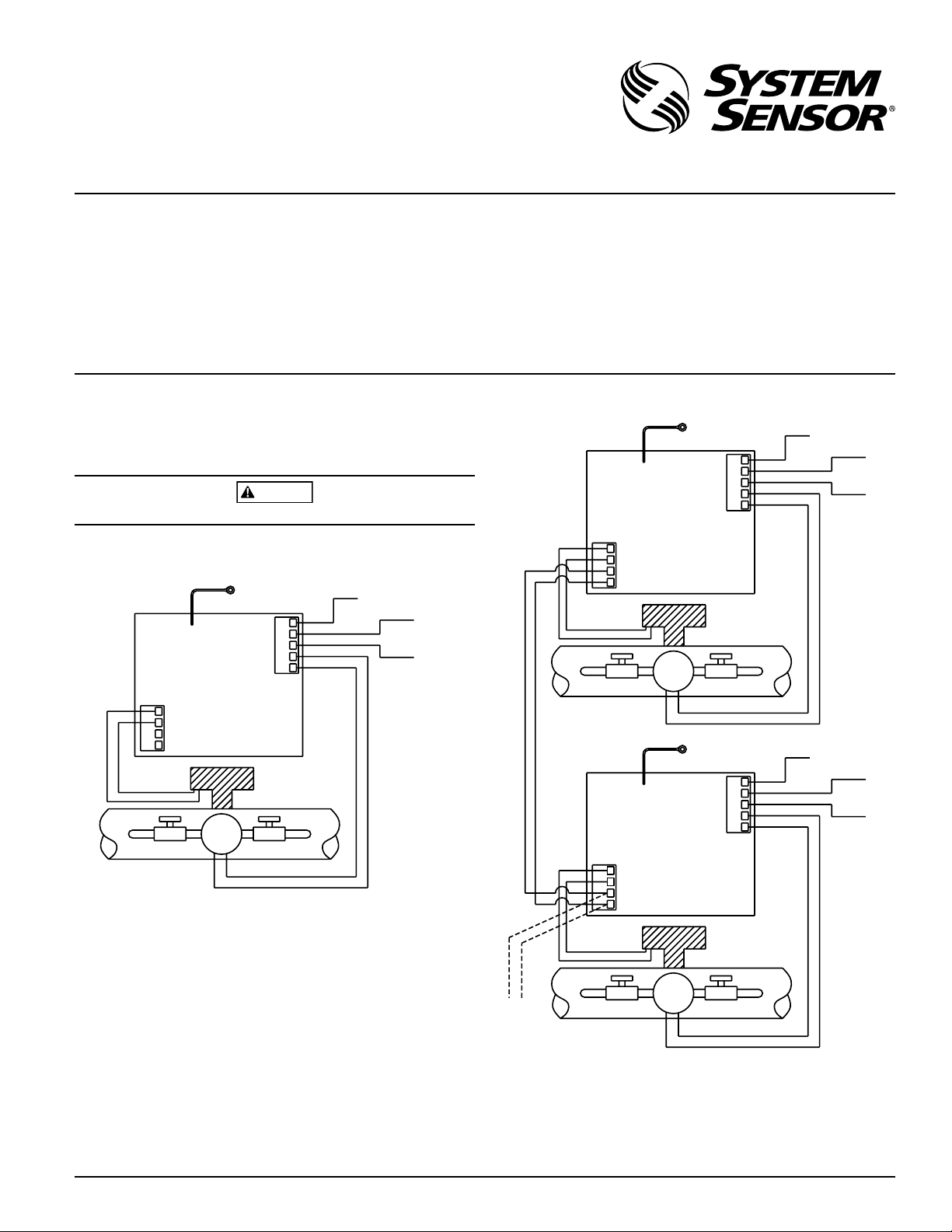
WIRING DIAGRAM FOR STAND ALONE APPLICATION
FOR INTERCONNECTING MULTIPLE ZONECHECK UNITS
}
}
WATERFLOW
DETECTOR
JUNCTION BOX
OR ATTACH TO
PUMP
AC POWER
AC GROUND
TO EARTH GND.
PUMP
PUMP
AC
AC
GND
INTER-CONNECT
WF INPUT
WARNING
ZCK-1, ZCK-1E, ZCK-1EG, ZCK-1EN and ZCK-50
Zonecheck Key Switch for Control and
3825 Ohio Avenue, St. Charles, Illinois 60174
1-800-SENSOR2, FAX: 630-377-6495
Monitoring of the Zonecheck Flow Switch Tester
ELECTRICAL SPECIFICATIONS
Operating Voltage: ZCK-1: 120V, 60Hz; ZCK-1E, ZCK-1EG, ZCK-1EN and ZCK-50: 220VAC, 50Hz, 7.5W Max.
Operating Temperature: 0°C to 49°C (32°F to 120°F)
Operating Humidity: 5% to 95% RH (non-condensing)
Mounting Options: Includes back box for surface or flush mounting.
For pre-wiring, use a 411/16˝ x 411/16˝ back box
Operation Modes: Self Test: Wired locally. Timed out, pump disabled after 2min ±15sec
Group Test: Interconnected
LED Operation: Ready state: No LED
Test initiation: Green LED
Flow switch activation: Red LED (ZCK-1), Green LED (ZCK-1E, ZCK-1EG, ZCK-1EN and ZCK-50) Tested to EN 61010-1
Note: Zonecheck key switch features a time out function in Self Test mode that
allows the user to start the flow switch test which will end automatically after
two minutes. The waterflow detector will be activated during the 2 minute
timeframe, upon activation the waterflow detection LED on the zonecheck
key switch will turn on and remain that way until the key is returned to the
standby position.
If this product is not used as specified, it may become impaired.
FIGURE 2: FOR INTERCONNECTING MULTIPLE ZONECHECK UNITS
TO EARTH GND.
OR ATTACH TO
JUNCTION BOX
GND
AC
AC
PUMP
PUMP
I56-1610-009R
www.systemsensor.com
AC GROUND
AC POWER
FIGURE 1: WIRING DIAGRAM FOR STAND ALONE APPLICATION
TO EARTH GND.
OR ATTACH TO
WF INPUT
}
INTER-CONNECT
}
PUMP
JUNCTION BOX
GND
AC
AC
PUMP
PUMP
WATERFLOW
DETECTOR
AC GROUND
NOTE: WF INPUT not required for key switch operation if waterflow detector is connected to a panel or other monitoring device. AC power and pump
wiring must conform to NEC or your local codes.
ZCK-1E, ZCK-1EG, ZCK-1EN AND ZCK-50
If the pump used in this application is grounded, it must share the same input/output earth ground as the device.
An overcurrent protection device such as a switch or circuit breaker is required. The protection device must be clearly marked and have a maximum
rating of 16 A.
There are no ventilation requirements.
PRE-OPERATION GUIDELINES
Contact central monitoring station or appropriate fire safety personnel prior
to testing Zonecheck.
AC POWER
W0158-00
WF INPUT
}
INTER-CONNECT
}
WATERFLOW
DETECTOR
PUMP
TO EARTH GND.
OR ATTACH TO
JUNCTION BOX
GND
AC
AC
PUMP
PUMP
TO NEXT
ZONECHECK
SWITCH FOR
INTERCONNECT
WF INPUT
}
INTER-CONNECT
}
PUMP
WATERFLOW
DETECTOR
AC GROUND
AC POWER
W0158-00
D770-31-00 1 I56-1610-009R
Page 2

WARNING
Only activate the Zonecheck key switch when the valves are opened and the
sprinkler system is full.
ZONECHECK TESTING: SELF-TEST MODE
ZCK-1
To activate the Zonecheck wired locally to the key switch insert key and turn
to the right. The green LED will illuminate to show that the pump has been
activated. After two minutes the green LED will turn off to show the pump
has been deactivated. The red LED will illuminate once the waterflow detector
has been activated and will remain on until the key is returned to the standby
position.
NOTE: The red LED will not illuminate if the waterflow detector is not wired
to the key switch. When testing has been completed, turn the key back to the
standby position.
ZCK-1E, ZCK-1EG, ZCK-1EN AND ZCK-50
To activate the Zonecheck wired locally to the key switch insert key and turn
to the right. Green LEDs will illuminate when either the pump or the waterflow detector are activated. After two minutes the pump led will turn off,
showing that the pump has been deactivated. The water flow detection LED
will remain on until the key is returned to the standby position.
NOTE: The LED for the waterflow detector will not illuminate if the detector
is not wired to the key switch. When testing has been completed, turn the key
back to the standby position.
ZONECHECK TESTING: GROUP-TEST MODE
All Zonecheck systems whose key switches are interconnected (refer to interconnecting wiring diagram), may be activated from any key switch. To initiate
the group test, insert key and turn to the left.
The LEDs on the key switch used to initiate the group test indicate the activity
for the Zonecheck unit and waterflow detector connected to that key switch only.
When testing has been completed, turn the key back to the standby position.
Please refer to insert for the Limitations of Fire Alarm Systems
System Sensor warrants its enclosed product to be free from defects in materials and
workmanship under normal use and service for a period of three years from date of
manufacture. System Sensor makes no other express warranty for the enclosed product.
No agent, representative, dealer, or employee of the Company has the authority to increase or alter the obligations or limitations of this Warranty. The Company’s obligation
of this Warranty shall be limited to the replacement of any part of the product which
is found to be defective in materials or workmanship under normal use and service
during the three year period commencing with the date of manufacture. After phoning
System Sensor’s toll free number 800-SENSOR2 (736-7672) for a Return Authorization
number, send defective units postage prepaid to: System Sensor, Returns Department, RA
D770-31-00 2 I56-1610-009R
©2010 System Sensor
Three-Year Limited Warranty
#__________, 3825 Ohio Avenue, St. Charles, IL 60174. Please include a note describing
the malfunction and suspected cause of failure. The Company shall not be obligated to
replace units which are found to be defective because of damage, unreasonable use,
modifications, or alterations occurring after the date of manufacture. In no case shall the
Company be liable for any consequential or incidental damages for breach of this or any
other Warranty, expressed or implied whatsoever, even if the loss or damage is caused by
the Company’s negligence or fault. Some states do not allow the exclusion or limitation of
incidental or consequential damages, so the above limitation or exclusion may not apply
to you. This Warranty gives you specific legal rights, and you may also have other rights
which vary from state to state.
 Loading...