

Page 1
D770-32-00 1 I56-0053-003R
Zonecheck
Flow Switch Tester
INSTALLATION AND MAINTENANCE INSTRUCTIONS
3825 Ohio Avenue, St. Charles, Illinois 60174
1-800-SENSOR2, FAX: 630-377-6495
www.systemsensor.com
Important
Please Read Carefully And Save
This instruction manual contains important information about the installation and operation of a Zonecheck Flow Switch Tester. Purchasers who
install waterflow detectors for use by others must leave this manual or a
copy of it with the user.
Read all instructions carefully before beginning. Follow only those instructions that apply to the model you are installing.
Use Zonecheck Flow Switch Testers in wet-pipe systems only. Do NOT use
them in dry pipe, deluge, or preaction systems.
Do not use in potentially explosive atmospheres. Do not allow unused
wires to remain exposed.
Principles Of Operation
Retrofit Model
Zonecheck Flow Switch Tester shall mount on any clear steel pipe span of
the appropriate nominal size, either in a vertical upflow or horizontal run,
between 6″ and 12″ from the flow switch. Flow Switch Tester shall consist
of a recirculating pump, operating at nominal 110V or 220V as appropriate,
two (2) sets of valves and elbows to facilitate the circulation of the water,
a System Sensor vane-type waterflow detector, and a key switch to activate
the recirculating pump. When activated, the pump shall circulate the water
within the sprinkler riser around the waterflow detector vane to simulate
the flow of one sprinkler head in operation. The activating key switch shall
provide the means to be wired locally to one Flow Switch Tester, or interconnected with other key switches for group activation. Flow Switch Tester
shall be available for manifold and retrofit installation applications.
Manifold Model Specifications
Zonecheck Flow Switch Tester manifold models shall consist of a schedule 10 pipe assembly of the appropriate nominal size. Manifold assembly
CAUTION
Specifications
Static Pressure Rating: 175 PSI
Operating Temperature Range: 32°F–120°F (0°C–49°C)
Compatible Pipe
(Manifold Models): Schedule 10, 2″–4″ diameter
Compatible Pipe
(Retrofit Models): Schedule 10 and 40, 2″–8″ diameter
(50 mm through 200 mm)
Service Use: Inspection, Testing and
Maintenance of Water-Based
Fire Protection Systems: NFPA 25;
National Fire Alarm Code: NFPA 72
Manifold Assembly Length
(Manifold Models): 25.6″ (65 cm)
Component Connections:
Manifold Models: Retrofit Models:
2 ea. - 1″ NPT/25mm 2 ea. - 1″ NPT/25mm British Standard
British Standard Thread elbows
Thread elbows 2 ea. - 25mm British Standard
Thread elbows
Valves: Red: Standard valve
Green: Contains check valve
Warranty: 3 years
shall provide grooved ends for accepting the appropriate grooved connection fittings. Manifold assembly shall include no less than two drain ports
with the appropriate drain plugs. Manifold Zonecheck models shall come
with the pump, valves, elbows, pipe assembly, drain plugs, and System
Sensor waterflow detector pre-assembled.
Manifold Models
Domestic Models with 1
10 V Pump Canadian Models with 110 V Pump
ZC20, ZC25, ZC30, ZC40 ZC20A, ZC25A, ZC30A, ZC40A
Retrofit Models
Domestic Models Canadian Models International Models
with 110 V Pump with 110 V Pump with 220 V Pump
ZCR20 ZCR20A ZCR20E
ZCR25 ZCR25A ZCR25E
ZCR30 ZCR30A ZCR30E
ZCR40 ZCR40A ZCR40E
ZCR60 ZCR60A ZCR60E
ZCR80 ZCR80A ZCR80E
Replacement Parts
ZCK-1 Zonecheck 110V Keyswitch ZCK-1E Zonecheck 220V Keyswitch
ZCP-110 Zonecheck 110V Pump ZCP-220 Zonecheck 220V Pump
Do NOT install Zonecheck on copper piping.
General Installation Recommendations
Before installing any waterflow-related device, be thoroughly familiar
with: NFPA 72: National Fire Alarm Code
NFPA 13: Installation of Sprinkler Systems, Section 3.17
NFPA 25: Inspection, Testing and Maintenance of Sprinkler Systems
CAUTION
Electrical Specifications
Pump Operating Voltages: Domestic/Canadian models:
1.63A@110 V, 60 Hz
International models: .88A@220 V, 50Hz
Key Switch Operating Voltage: ZCK-1 110V, 60Hz; ZCK-1E: 220V, 50Hz
Key Switch Mounting Options: Includes back box for surface or flush
mounting. For pre-wiring, use a
411/16″ x 411/16″ back box
Key Switch Operation Modes: Self-test: Wired locally
Group test: Interconnected
Key Switch LED Operation: Ready state: No LED
Test Initiation: Green LED
Flow switch activation: Red LED
Page 2
Zonecheck pump) on the other. IMPORTANT: There are two
Zonecheck valves enclosed with each Retrofit kit: 1.) A ‘Red’-handled
valve, which is a standard valve that serves as an inlet valve; and, 2.)
A ‘Green’-handled valve, which is an outlet valve that contains a check
valve. The valves must be oriented properly for Zonecheck to work
correctly. If mounting Zonecheck to a vertical riser, attach the Red
valve so that it will be above the pump, as the assembly would appear
after installion (See Figure 1 for illustration). If mounting Zonecheck
to a horizontal run of pipe, attach the red valve so that it will be downstream, in relation to the sprinkler system waterflow, from the
Zonecheck pump (See Figure 1 also). Attach the mechanical tees (supplied by others), ensuring that both tees are parallel to each other and
perpendicular to the Zonecheck assembly. Ensure that all joints are
tight and set the entire assembly aside.
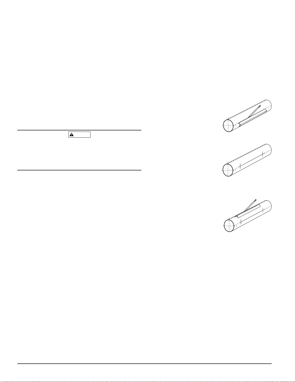
3. Place the aluminum angle template on the pipe (leg ends contacting
pipe surface) locating one edge of the leg where the mechanical tee
holes will be drilled. Scribe or draw a pencil line on the
pipe the full length of the template. Note: Ensure
that both legs of the aluminum template
are in complete contact along their
entire length with the pipe surface to
ensure that the scribed line will run
along the center line of the pipe. Failure
to follow this step may cause damage to the Zonecheck product or
leakage.
4. Measure the center-to-center distance between the
mechanical tees and transfer that measured distance to the scribed line on the pipe surface. IMPORTANT: Ensure that the
markings on the pipe are located so
that the stripes on the Zonecheck pump
housing will be parallel to the floor
after installation (See Figure 1 for installation). Failure to follow this
step may result in pump seizure.
5. The Waterflow detector will typically mount to the pipe 90 degrees from
the location of the pump, as space permits. To determine
the location of the flow switch, scribe a second line
parallel to the line made in Step 3 and mark the
midpoint between the mechanical tees
This intersection line will locate the hole
for the waterflow device. Ensure that this
location will permit access to both the
detector and the Zonecheck assembly. If
located on horizontal pipe, ensure that the waterflow detector, once
mounted, will be located on the topside of the pipe. Ensure that the
intended location does not result in the detector being mounted upsidedown, as condensation may collect in the housing and impair the operation of the detector. See Figure 1 for illustration.
6. Refer to the suggested hole size requirements from the mechanical tee
manufacturer and the waterflow manufacturer and drill the three holes
where marked in Steps 4 & 5. IMPORTANT: Before drilling, verify that
the stripes on the Zonecheck pump housing will be parallel to the floor
after installation, as noted in Step 4 (See Figure 1 for illustration).
When drilling the holes with a hole saw, make certain that the center
of the cut does not remain in the pipe. Clean the outside of the pipe to
remove dirt, metal chips, and cutting lubricant.
7. Mount the completed Zonecheck assembly to the sprinkler pipe.
Secure the U-bolts of the mechanical tees and tighten to manufacturer’s recommended torque.
8. Remove the waterflow detector from the carton and install on pipe.
The direction-of-flow arrow shown on the saddle must match the
direction of the waterflow in the pipe. Refer to the manufacturer’s
instructions for mounting the waterflow detectors.
9. Refer to the wiring diagram (see Figure 2.) for proper electrical connections for stand-alone or multiple unit keyswitch installation.
Other applicable NFPA standards, local codes, and the requirements of the
authority having jurisdiction also apply.
Failure to follow these directions may prevent the device from reporting
the flow of water in the event the associated sprinkler system is activated
by a fire. System Sensor is not responsible for devices that have been
improperly installed, tested, or maintained.
1. Mount the Zonecheck Flow Switch Tester where there is adequate
clearance for installation and removal and a clear view of it for inspections.
2. When installing a manifold model, locate 6 to 7 feet above the floor to
protect from possible damage. When installing a retrofit model, mount
between 6″ and 12″ from the flow switch.
3. On horizontal runs, orient the Zonecheck Flow Switch Tester on the
side of the pipe only. Failure to do so may impair the operation of the
Zonecheck pump (see Figure 1). For vertical flow applications, mount
the Zonecheck Flow Switch Tester on pipe through which water flows
upward. Otherwise, the unit may not operate properly.
4. Mount the Zonecheck Flow Switch Tester at least 6 inches from a fitting that changes the direction of water flow and no less than 24 inches from a valve or drain.
5. Be sure the direction-of-flow arrow shown on the saddle matches the
direction of the waterflow in the pipe.
Before installing a Zonecheck Flow Switch Tester:
1. Contact central monitoring station or appropriate fire safety personnel
before installing the Zonecheck Flow Switch Tester.
2. Identify and close tightly the sprinkler system’s zone valve.
3. Close both (Red & Green) Zonecheck valves.
4. Drain the sprinkler zone.
Installation Guidelines
Manifold Model
1. Remove the assembled manifold unit from the carton.
2. Prepare to install the manifold unit to the riser. If mounting the manifold unit to a vertical riser, orient the assembly with the red valve
above the Zonecheck pump. If mounting the manifold to a horizontal
waterflow pipe, orient the assembly with the red valve on the downstream end of the waterflow pipe (see Figure 1). Verify that the stripes
on the Zonecheck pump housing will be parallel to the floor after
installation. If Zonecheck will be located on a horizontal pipe, ensure
that the waterflow detector, once mounted, will be located on the topside of the pipe (see Figure 1 for illustration). Ensure that the intended location does not result in the detector being mounted upside
down, as water may collect in the housing and impair the operation of
the detector.
3. Mount the Schedule 10 pipe (to which the Zonecheck pump and
Waterflow Detector are mounted) to the riser using industry-accepted
practices in conjunction with applicable NFPA standards, local codes,
and the authority having jurisdiction.
4. Refer to the wiring schematic for proper electrical connections for
stand-alone or multiple unit keyswitch installation.
Retrofit Model
1. Remove contents from the carton.
2. Assemble the Zonecheck unit. If the mechanical tees used to attach the
Zonecheck unit to the sprinkler pipe have a British Standard Pipe
Thread (BSPT) outlet, select the elbows contained within the bag
marked ‘BSPT/BSPT’. If the mechanical tees have an NPT thread outlet, select the elbows contained within the bag marked ‘NPT/BSPT’
(Note: the embossed ‘A’ on the elbow designates the NPT thread).
Choose the appropriate elbows. Connect the BSPT threaded end of the
90-degree elbows to each of the Zonecheck valves, insert the gasket
into the valve, and connect each valve to the correct side of the
Zonecheck pump. Each valve has a female BSPT threaded end (connected to the elbow) on one side and a male union (connected to the
CAUTION
D770-32-00 2 I56-0053-003R
Page 3

Figure 2. Wiring Diagrams
D770-32-00 3 I56-0053-003R
WIRING DIAGRAM FOR STAND ALONE APPLICATION
}
}
FOR INTERCONNECTING MULTIPLE ZONECHECK UNITS
}
}
}
}
AC POWER AND PUMP WIRING
MUST CONFORM TO NEC OR
YOUR LOCAL CODES.
OR OTHER MONITORING DEVICE.
WATERFLOW
DETECTOR
KEYSWITCH OPERATION IF WATERFLOW
DETECTOR IS CONNECTED TO PANEL
WF INPUT NOT REQUIRED FOR
NOTE:
AC GROUND
AC POWER
GND
JUNCTION BOX
AC
PUMP
PUMP
AC
WF INPUT
WATERFLOW
DETECTOR
INTER-CONNECT
PUMP
TO EARTH GND.
OR ATTACH TO
JUNCTION BOX
OR ATTACH TO
JUNCTION BOX
OR ATTACH TO
INTERCONNECT
SWITCH FOR
ZONECHECK
TO NEXT
AC GROUND
AC POWER
GND
AC
PUMP
PUMP
AC
TO EARTH GND.
PUMP
WF INPUT
INTER-CONNECT
PUMP
AC POWER
AC GROUND
TO EARTH GND.
PUMP
PUMP
AC
AC
GND
INTER-CONNECT
WF INPUT
WATERFLOW
DETECTOR
Figure 1. Zonecheck Installation
Correct Horizontal Installation
Correct Vertical Installation
Incorrect Horizontal Installation Incorrect Horizontal Installation
RED VALVE
WATERFLOW
DETECTOR
GREEN
VALV E
ZONECHECK
PUMP
RED VALVE
GREEN
VALV E
ZONECHECK
PUMP
WATERFLOW
DETECTOR
ZONECHECK
PUMP
ZONECHECK
PUMP
CORRECT
Pump stripes
(horizontal)
INCORRECT
Pump stripes
(vertical)
Page 4

D770-32-00 4 I56-0053-003R
©
2000 System Sensor
Three-Year Limited Warranty
System Sensor warrants its enclosed Zonecheck Flow Switch Tester to be
free from defects in materials and workmanship under normal use and
service for a period of three years from date of manufacture. System Sensor
makes no other express warranty for this Flow Switch Tester. No agent, representative, dealer, or employee of the Company has the authority to
increase or alter the obligations or limitations of this Warranty. The
Company’s obligation of this Warranty shall be limited to the repair or
replacement of any part of the Flow Switch Tester which is found to be
defective in materials or workmanship under normal use and service during the three year period commencing with the date of manufacture. After
phoning System Sensor’s toll free number 800-SENSOR2 (736-7672) for a
Return Authorization number, send defective units postage prepaid to:
System Sensor, Repair Department, RA #__________, 3825 Ohio Avenue,
St. Charles, IL 60174. Please include a note describing the malfunction and
suspected cause of failure. The Company shall not be obligated to repair or
replace units which are found to be defective because of damage, unreasonable use, modifications, or alterations occurring after the date of manufacture. In no case shall the Company be liable for any consequential or
incidental damages for breach of this or any other Warranty, expressed or
implied whatsoever, even if the loss or damage is caused by the Company’s
negligence or fault. Some states do not allow the exclusion or limitation of
incidental or consequential damages, so the above limitation or exclusion
may not apply to you. This Warranty gives you specific legal rights, and
you may also have other rights which vary from state to state.
1. Zonecheck Flow Switch Testers may not work or operate properly if
sprinkler piping being monitored is plugged with pipe scale, mud,
stones or other foreign material. Sprinkler systems should be checked
regularly for such blocking material, following the instructions in
Chapter 5 of NFPA Standard 13A.
The Limitations of Zonecheck Flow Switch Tester
WARNING
2. All valves controlling a sprinkler water supply should be sealed or
locked in the normally open position. The normally open position
should be monitored by a sprinkler supervisory switch.
Please refer to insert for the Limitations of Fire Alarm Systems
Pre-Operation Guidelines
Contact central monitoring station or appropriate fire safety personnel
prior to testing Zonecheck.
Zonecheck Testing: Self-Test Mode
To activate the Zonecheck wired locally to the ZCK-1 key switch (refer to
stand-alone wiring diagram), insert key and turn to the right. The green
LED on the ZCK-1 will illuminate to show that the pump has been activated. The red LED on the ZCK-1 will illuminate once the waterflow detector has been activated. The red and green LEDs will remain illuminated
until the key is switched to the standby position. NOTE: The red LED will
not illuminate if the waterflow detector is not wired to the ZCK-1 key
switch. When testing has been completed, turn the key back to the standby position.
Only activate the Zonecheck ZCK-1 key switch when the valves are
opened and the sprinkler system is full.
WARNING
Zonecheck Testing: Group-Test Mode
All Zonecheck systems whose ZCK-1 key switches are interconnected
(refer to interconnecting wiring diagram), may be activated from any ZCK1 key switch. To initiate the group test, insert key and turn to the left.
The LEDs on the key switch from where the group test was initiated only
indicate the activity for the Zonecheck connected directly to that key
switch. The red and green LEDs will remain illuminated until the key is
switched to the standby position.
When testing has been completed, turn the key back to the standby
position.
Trouble Shooting Recommendations for Zonecheck Flow Switch
Tester
The unit fails to activate the remote alarm signal
1. Is there power to the circulator, i.e. Zonecheck pump?
2. Is the impeller spindle turning? If not, switch off at the key switch.
Turn the spindle manually with a screwdriver for several turns then
switch on the keyswitch.
3. Is the circulator fitted correctly for the flow of water to move the paddle?
4. Is the green handled valve fitted on the delivery side of the circulator?
5. Are the Zonecheck valves in the “open” position?
6. Is the signal wiring operating correctly? Check the wiring.
After installing a Zonecheck Automatic Flow Switch Tester:
1. Backfill and hydraulically test the system.
2. Contact central monitoring station or appropriate fire safety personnel.
3. Open the main isolation valve slowly until fully opened.
4. Open both Zonecheck valves fully.
CAUTION
 Loading...