

Page 1
INSTALLATION AND MAINTENANCE INSTRUCTIONS
XR2 Detector Installation/Removal
Tool for use with System Sensor
Plug-in Detectors
General Description
The XR2 Detector Installation/Remov al Tool is designed for
use with System Sensor plug-in smoke detectors. This tool
permits installation and removal of detectors in elevated
mounting locations up to 18 feet (5.5 meters) high when it
is used with XP-4 extension poles (ordered separately).
Tool Assembly And Disassembly
The XR2 installation/removal tool consists of a head assembly and connecting tube that is used with a set of XP-4
extension poles sold separately (see Figure 1).
To assemble the tool, attach the head assembly to one of
the XP-4 extension poles by sliding the small end of the top
extension pole into the coupler end of the head assembly . A
hole near the end of the tube on the head assembly fits
over the button of the extension pole to lock the head assembly to the extension pole. The extension poles lock to
each other in the same way.
To disassemble, depress the lock button until the head assembly can be disengaged from the extension poles. The
extension poles can be separated from each other in the
same manner.
Detector Installation
To install a System Sensor plug-in detector into a low profile base:
1. Insert and rotate the detector head into the installation
and removal tool until the detector head bottoms and
snaps into place.
2. Raise the tool to the ceiling until the detector head enters
the mounting base and the locking ears on the detector
head meet the ring inside the mounting base.
A Division of Pittway
3825 Ohio Avenue, St. Charles, Illinois 60174
1-800-SENSOR2, FAX: 630-377-6495
3. Rotate the tool clockwise until the locking ears enter
their respective slots.
4. Continue rotating the tool until the detector is fully engaged in the base. When this happens the detector cannot be rotated any further.
NOTE: For conventional detectors, the detector automati-
cally defeats the locking feature on the shorting
spring in the base and then re-engages it, so that
the next detector receives power from the alarm
system.
5. Carefully pull the tool from the detector head.
Detector Removal
To remove a System Sensor low profile plug-in detector
head from a base:
1. Raise the installation/removal tool to ceiling height, locate the tool over the detector, and push up and rotate
until the tool snaps onto the detector head.
2. Rotate the tool counterclockwise until the detector disengages from the mounting base.
3. Lower the tool slowly and make certain that the detector head is disengaged completely.
4. Continue lowering the tool. When the detector head is
at floor level, the detector can be remo v ed fr om the tool
for inspection, testing, or cleaning.
Notes:
1. On conventional bases, when the detector is removed,
the shorting jumper remains defeated; it does not complete the circuit by connecting the + IN and + OUT
terminals. This should cause a fault or trouble condition
at the panel. The jumper must be set manually.
2. Plug-in bases have a built-in tamper-resist feature that,
if activated, must be disabled before the removal tool
Figure 1. XR2 Detector Installation/Removal Tool and XP-4 Extension Pole:
1 I56-588-03
A78-2437-00
Page 2
can be used. See the instruction sheet packed with the
detector head for instructions on disabling the tamperresist feature.
Magnetic Testing
To attach the magnet to the pole:
1. Pull the connecting pin and remove the Installation/Removal head from the pole assembly.
2. Push and hold the lock button, and remove the connecting tube from the pole.
3. Remount the other end of the connecting tube to the
pole, making sure that the lock button snaps into place.
4. Slide the magnet into the slots and cover with the plastic
cap.
NOTE: Shipping bag with magnet may be tied to connect-
ing pin ring.
To Test The Detector:
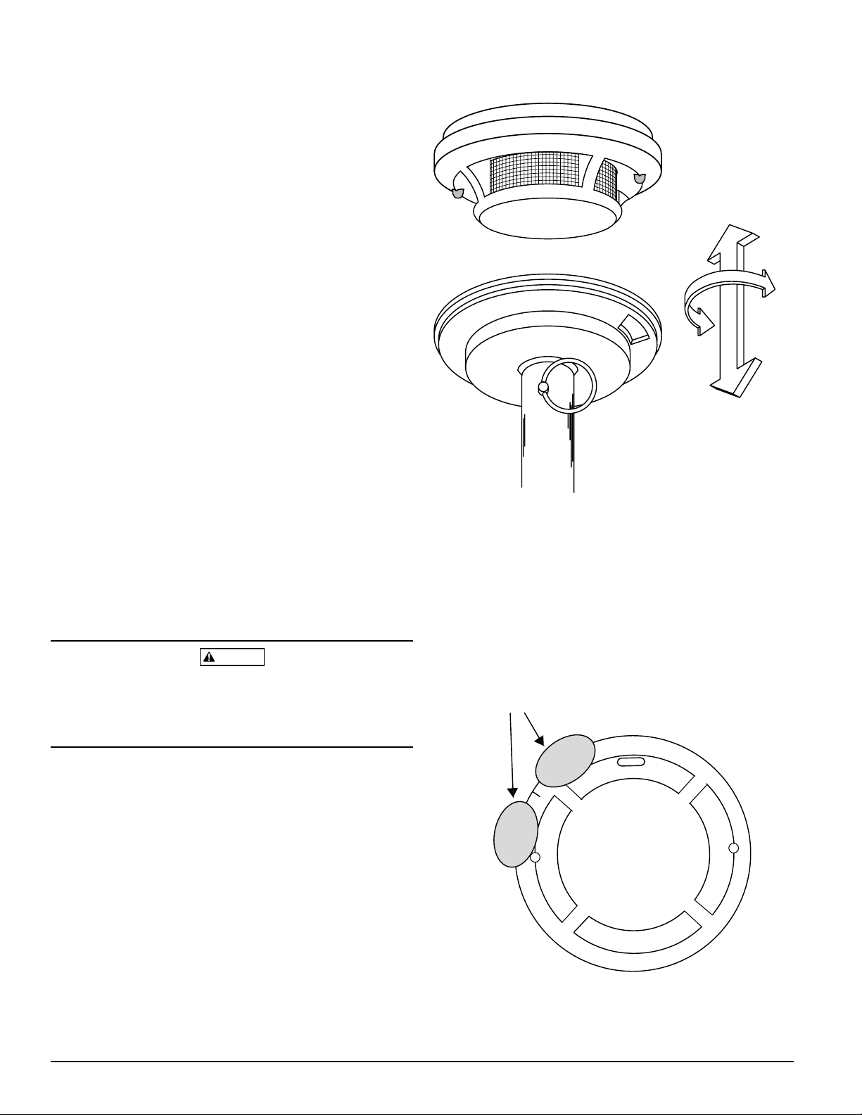
1. Hold the test magnet near the raised mark on the smoke
detector in one of the test areas shown in Figure 3.
NOTE: If the smoke detector does not alarm after 20 sec-
onds, move the magnet to the other test area and
repeat.
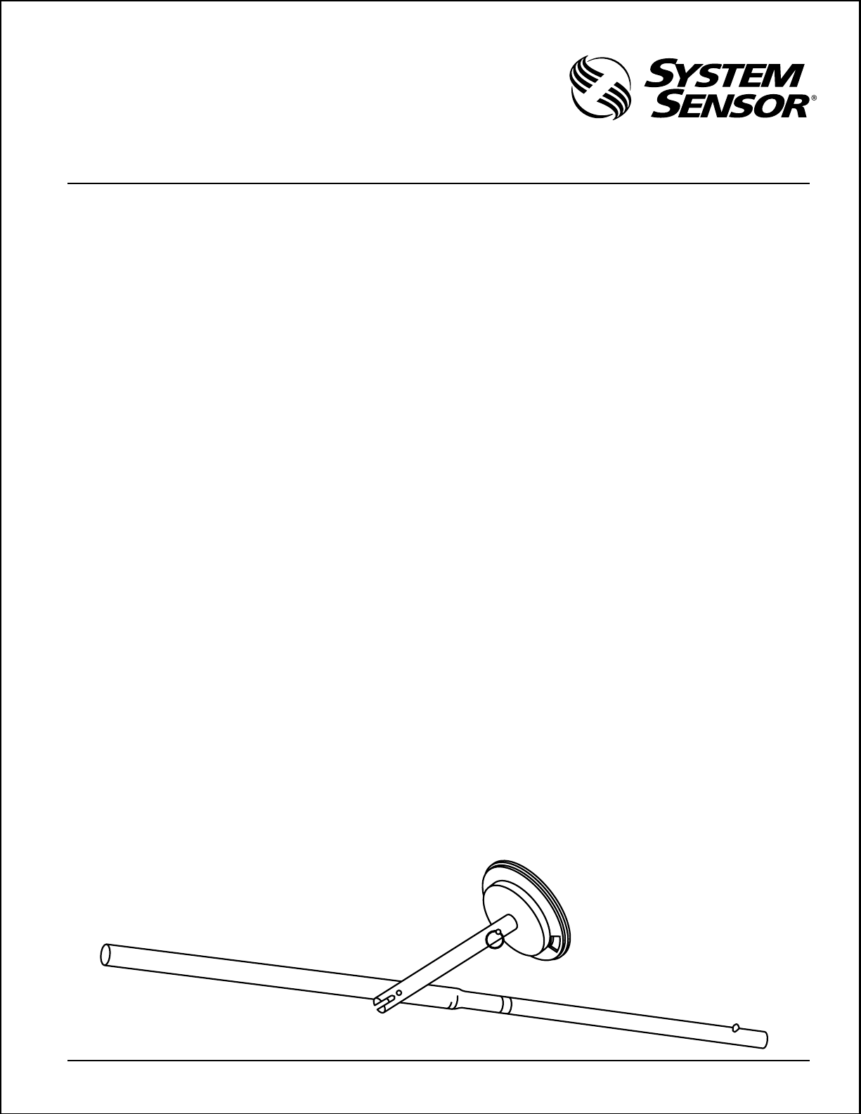
Figure 2. Insertion of detector head into cup of XR2:
2. Smoke detector LEDs should light and panel should indicate alarm.
3. Push the reset button on the panel to reset the smoke
detector.
4. See the smoke detector manual for additonal information.
WARNING
When using the XR2 removal tool with the XP-4 extension
poles, avoid any contact with overhead wiring. The wood
insulators in the extension poles are not effective in all
shock hazard situations.
A78-2438-00
Figure 3:
MAGNET TEST AREAS
D
O
N
O
2 I56-588-03
T
N
I
A
P
T
A78-2424-01
© System Sensor 1996
 Loading...