

Page 1
INSTALLATION AND MAINTENANCE INSTRUCTIONS
3825 Ohio Avenue, St. Charles, Illinois 60174
1-800-SENSOR2, FAX: 630-377-6495
www.systemsensor.com
SpectrAlert Advance
Weatherproof Plate
For use with models WTP-SP, WTP-SPW
SPECIFICATIONS
Operating Temperature: -40° F to 151° F (-40° C to 66° C)
Enclosure Rating: Meets NEMA 3R, IP22 rating requirements
WALL PRODUCT LENGTH WIDTH DEPTH FROM WALL
Speaker Strobe 7.25˝ 6.26˝ 3.0˝ Including Speaker and Lens
Speaker 7.25˝ 6.26˝ 1.3˝ Including Speaker
Note: This product may only be installed in conjunction with an outdoor SpectrAlert Advance Speaker or Speaker Strobe
Models: SPRK-R, SPSRK-R, SPWK-R, SPSWK-R, SPWK, SPRK, SPSWK, SPSWK-P, SPSRK, SPSRK-P (-R models ship minus the outdoor back box , standard
outdoor and -P models ship with an outdoor back box which is not needed when using the weatherproof plate)
Notice: This manual shall be left with the owner/user of this equipment.
Note: This product meets NEMA 3R for indoor or outdoor use to provide a
degree of protection against falling dirt, rain, sleet, or snow; and that will be
undamaged by the external formation of ice on the enclosure.
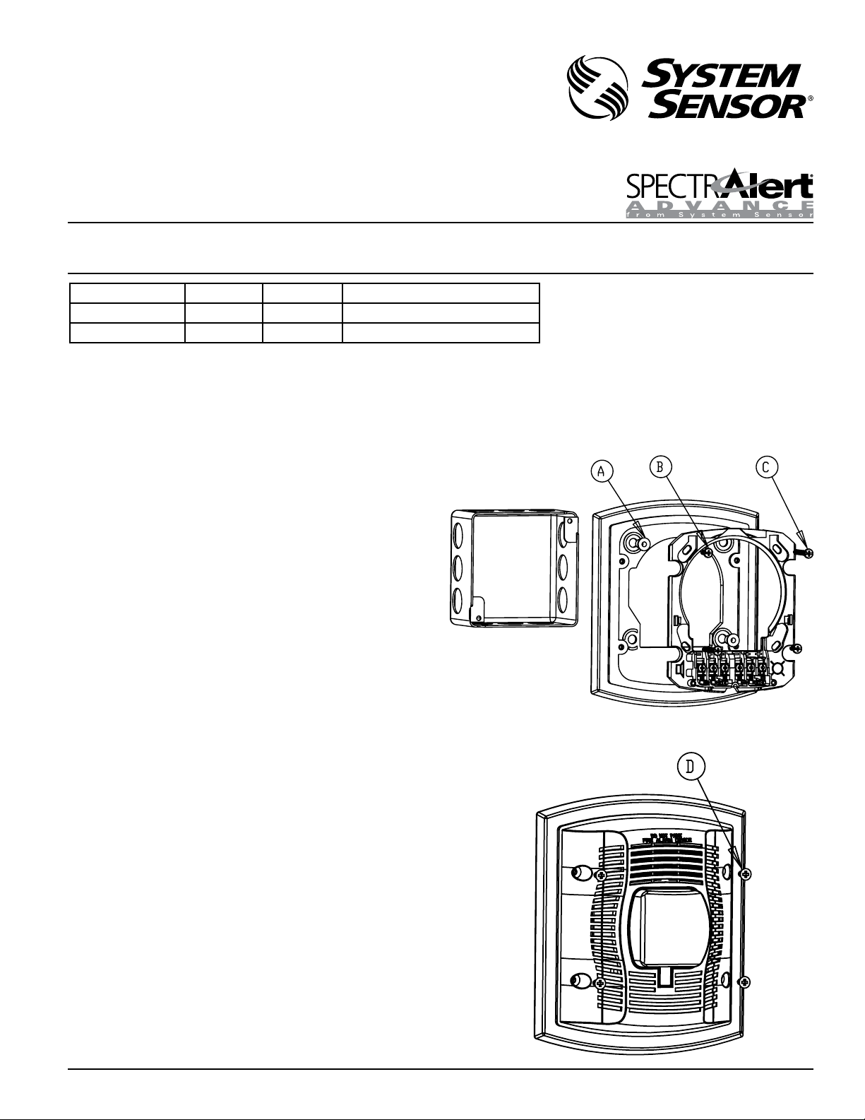
FIGURE 1: WTP-SP AND DEVICE MOUNTING PLATE ASSEMBLY AND
ATTACHMENT TO BACK BOX.
I56-3385-002R
GENERAL DESCRIPTION
For installation with SpectrAlert Advance outdoor or outdoor replacement (-R)
speakers and speaker strobes. This accessory plate allows an outdoor unit to
be flush mounted on a number of different surfaces including brick, ceramic
tile, concrete and masonry brick. The weatherproof plate is offered in red and
white and is sold separately from the device.
INSTALLATION:
1. The WTP-SP series of products may be used indoors or outdoors. They
must be installed using the proper SpectrAlert Advance K series product.
Do not attempt to use weatherproof plates with devices other than those
specified for use with this product.
2. Attach device mounting plate to the WTP-SP as shown in Fig 1. The
WTP-SP is compatible with 4x4x2-1/8” back boxes.
a. Check orientation of the back box to the WTP-SP plate and observe
which holes will be used for mounting to the back box
b. Place Well Nuts (A) into the two holes that will NOT be used in
mounting the WTP-SP to the back box (See Fig. 1).
c. Place the device mounting plate on the WTP-SP and secure using the
two #8-32 x ½” pan head screws (B) into the Well Nuts.
d. Secure the WTP-SP and device mounting plate assembly to the back
box (C) using the two #8-32 x 2” pan head screws.
e. Tighten screws until the WTP-SP assembly contacts the wall surface
evenly.
3. It is the responsibility of the installer to make sure that all openings and
connections are sealed properly. An outdoor rated silicon caulk (not
supplied) may be applied around the WTP-SP to fill in around grout lines
or uneven surfaces.
4. Connect field wiring to terminals. Please follow instruction manual supplied with the device.
5. Attach the device to the mounting plate by hooking the tabs on the device housing into the grooves on the mounting plate. Then, swing product into position to engage the pins on the device with the terminals
on the mounting plate. Make sure that the tabs on the back are fully
engaged with the mounting plate.
6. Secure the device to the WTP-SP (See Fig. 2), using the four #8-32 x 3/8”
flat head screws (D).
A0429-00
FIGURE 2:DEVICE AND WTP-SP ASSEMBLY.
A0430-00
SS-110-004 1 I56-3385-002R
Page 2

Please refer to insert for the Limitations of Fire Alarm Systems
System Sensor warrants its enclosed product to be free from defects in materials and
THREE-YEAR LIMITED WARRANTY
workmanship under normal use and service for a period of three years from date of
manufacture. System Sensor makes no other express warranty for this product. No agent,
representative, dealer, or employee of the Company has the authority to increase or alter
the obligations or limitations of this Warranty. The Company’s obligation of this Warranty
shall be limited to the replacement of any part of the product which is found to be defective in materials or workmanship under normal use and service during the three year
period commencing with the date of manufacture. After phoning System Sensor’s toll
free number 800-SENSOR2 (736-7672) for a Return Authorization number, send defective units postage prepaid to: System Sensor, Returns Department, RA #__________, 3825
Ohio Avenue, St. Charles, IL 60174. Please include a note describing the malfunction and
suspected cause of failure. The Company shall not be obligated to replace units which
are found to be defective because of damage, unreasonable use, modifications, or alterations occurring after the date of manufacture. In no case shall the Company be liable
for any consequential or incidental damages for breach of this or any other Warranty,
expressed or implied whatsoever, even if the loss or damage is caused by the Company’s
negligence or fault. Some states do not allow the exclusion or limitation of incidental or
consequential damages, so the above limitation or exclusion may not apply to you. This
Warranty gives you specific legal rights, and you may also have other rights which vary
from state to state.
SS-110-004 2 I56-3385-002R
©2009 System Sensor
 Loading...