

Page 1
INSTALLATION AND MAINTENANCE INSTRUCTIONS
CAUTION
31/4˝
1
3
/4˝
3
1
/4˝
PIPE TEE FITTING
PLASTIC VANE
TEE DEPTH
REFER TO
TEE DEPTH
TABLE
INSTALLATION GAGE
END OF PADDLE TREE MUST
FIT BETWEEN TOP OF TEE
AND BOTTOM OF HEX TEE
ADAPTOR FLANGE
HEX TEE
ADAPTOR
1˝ NPT THREAD
WATER FLOW
ACTUATOR
ASSEMBLY
FLOW
ACTUATOR
LEVER
TAMPER
PROOF
WRENCH
(P/N WFDW)
COVER
GROUND
SCREW
(GREEN)
MOUNTING
PLATE
PADDLE
FILLISTER
HEAD
SCREW
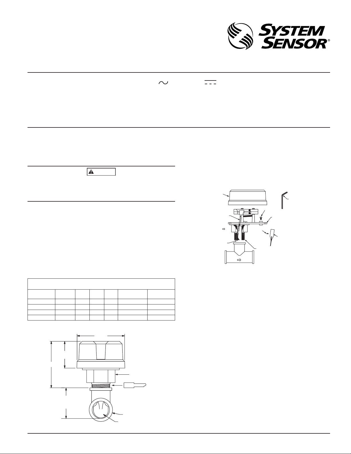
WFDTNR Vane-type Waterflow Detector
SPECIFICATIONS
Contact Ratings: 10 A @ 125/250 VAC ; 2.5 A @ 24 VDC
Triggering Threshold Bandwidth (Flow Rate): 4 to 10 GPM
Static Pressure Rating: 250 PSI (Max.)
Dimensions (Installed): 31⁄4 in H × 31⁄4 in W × 41⁄4 in D; 31⁄4 in above pipe tee
Operating Temperature Range: 32°F to 120°F (0°C to 49°C)
Shipping Weight: 1.5 lbs
Enclosure Rating: IP56
U. S. Patent Number: 5,213,205
IMPORTANT
Please Read Carefully And Save
This instruction manual contains important information about the installation
and operation of waterflow detectors. Purchasers who install waterflow detectors for use by others must leave this manual or a copy of it with the user.
Read all instructions carefully before beginning.
Use vane-type waterflow detectors in wet-pipe systems only. DO NOT USE IN
DRY-PIPE, DELUGE, OR PRE-ACTION SYSTEMS. The sudden inrush of water
in such systems may break the vane off or damage the mechanism. Do not use
in potentially explosive atmospheres. Do not leave unused wires exposed.
INSTALLATION GUIDELINES
Before installing any waterflow alarm device, be thoroughly familiar with:
NFPA 72: Installation, Maintenance and Use of Local Protective Signalling Systems
NFPA 13: Installation of Sprinkler Systems, specifically Section 3.17
NFPA 25: Inspection, Testing and Maintenance of Sprinkler Systems, specifi-
cally Chapters 4 and 5, and Section 5.3.3.2
NFPA 13D: Standard for Residential Dwellings
NFPA 13R: Standard for Multifamily Dwellings
FIGURE 2. ASSEMBLY DIAGRAM:
I56-0509-009R
3825 Ohio Avenue, St. Charles, Illinois 60174
1-800-SENSOR2, FAX: 630-377-6495
www.systemsensor.com
PRINCIPLES OF OPERATION
Vane-type waterflow detectors mount to wet-pipe systems only. Water flow in
the pipe deflects a vane. Deflection of the vane produces a switched output.
All detectors will activate on a sustained flow of water greater than 10 gallons
per minute (gpm) but will not activate if the flow rate is less than 4 gpm.
COMPATIBLE PIPE TEES/RISERS
Model WFDTNR fits 1- to 11⁄2-inch NPT threaded ferrous and brass, 1- to
2-inch sweat brass, 11⁄2-inch polybutylene plastic and 1-inch pvc plastic tees
having a 1-inch threaded NPT branch (see Figure 1 and chart for recommended tee depths). For 2-inch cast and malleable threaded tees use 2-inch
paddle (P02-0023-00) provided. Use 1-inch CPVC paddle when installing detector on 1-inch slip by 1-inch slip by 1-inch FPT NIBCO tee.
APPROXIMATE TEE DEPTH REQUIREMENTS (SEE FIGURE 1)
Tee Depth Threaded Sweat Poly B CPVC
1 × 1 × 1˝ 21/8˝ 13/4˝ N/A 21/4˝ 215/32˝ 213/16˝
1
1
/4 × 11/4 × 1˝ 21/2˝ 21/6˝ N/A N/A N/A N/A
1
1
/2 × 11/2 × 1˝ 23/4˝ 21/4˝ 21/2˝ N/A N/A N/A
2 × 2 × 1˝ 3
1
/4˝ 23/4˝ N/A N/A N/A N/A
CPVC/Spears/
Victaulic
FIGURE 1. MOUNTING DIMENSIONS:
CPVC/Tyco
Other applicable NFPA standards, local codes and the requirements of the
authority having jurisdiction.
Failure to follow these directions may result in failure of the device to report
a waterflow condition. System Sensor is not responsible for devices that have
been improperly installed, tested or maintained.
1. Mount the detector where there is adequate clearance for installation and removal
and a clear view of it for inspection. See Figure 1 for mounting dimensions.
2. Locate to protect from damage, 6-7 feet above the floor.
3. On horizontal runs, position the detector on top of the pipe or on the
side. Do not mount it upside down.
4. Mount detector at least 6 inches from a fitting which changes the direction of the water flow.
5. BE SURE DIRECTION-OF-FLOW ARROW MATCHES ACTUAL DIRECTION OF FLOW IN THE PIPE.
MOUNTING INSTRUCTIONS
1. This WFDTNR waterflow detector is designed to fit only the appropriate tee fitting.
N770-06-00 1 I56-0509-009R
W0124-00
NOTE: Leg of tee perpendicular to flow of water must have a 1-inch NPT
thread. Do not use a reducer to achieve the correct thread size. Failure
to follow this instruction will result in failure of the detector to report a
waterflow condition.
2. WFDT units are shipped without the paddles mounted to the actuator.
Select the correct size paddle for the tee being used the appropriate nominal pipe diameter size is molded on the surface of the paddles. Align hole
on stem of paddle with hole on actuator lever. Fasten together using a
#4-40×1⁄4-inch fillister head screw supplied in bag assembly. See Figure
2. Use only the screw provided with the WFDTNR. Drive screw head
W0125-00
Page 2
through hole in paddle until it seats firmly to actuator lever surface. No
CAUTION
WARNING
+
+
–
–
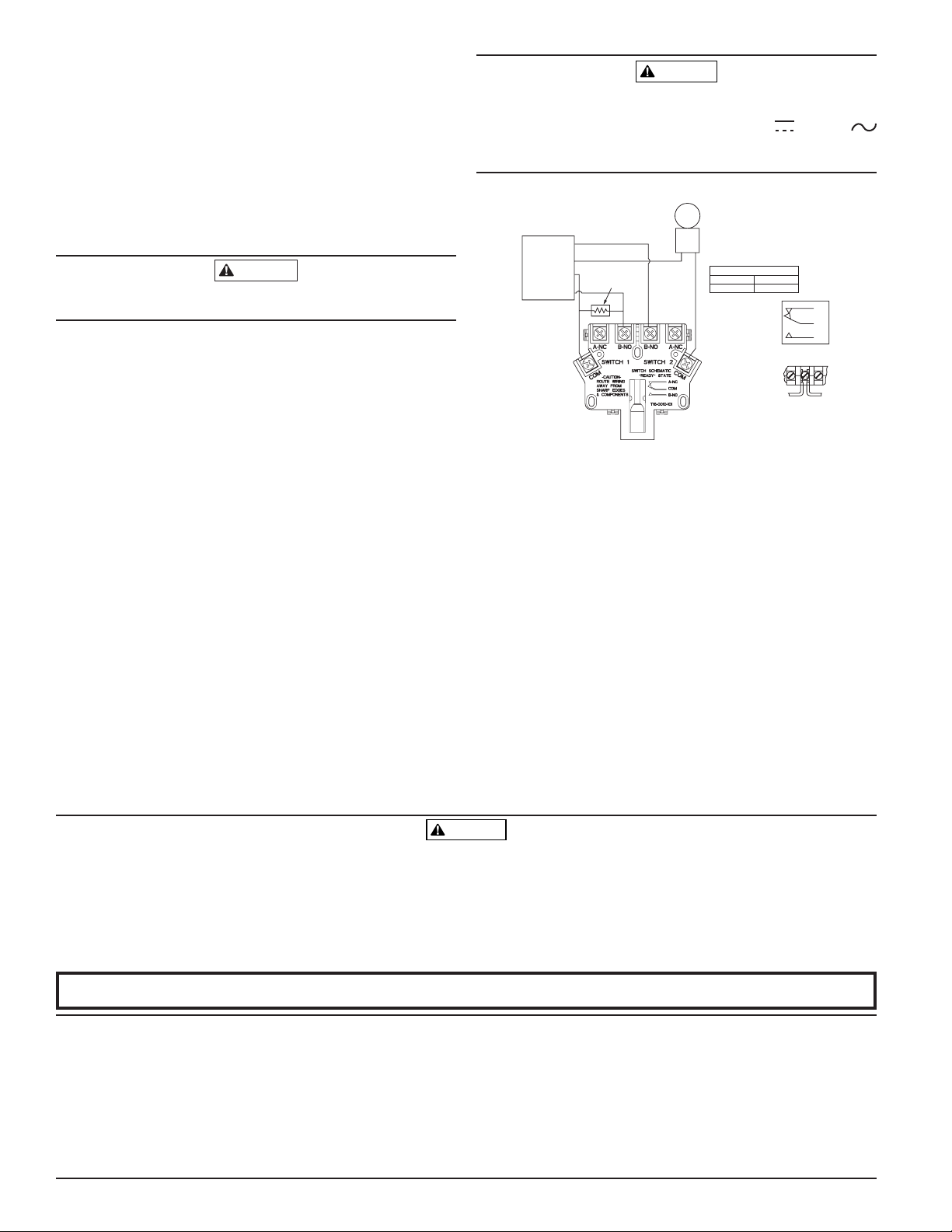
SSM24-X
SSV120-X
NOTE: COMMON AND B-NO
CONNECTIONS WILL CLOSE
WHEN VANE IS DEFLECTED, I.E.,
WHEN WATER IS FLOWING. DUAL
SWITCHES PERMIT
APPLICATIONS TO BE COMBINED
ON A SINGLE DETECTOR.
BREAK WIRE AS
SHOWN FOR
SUPERVISION OF
CONNECTION. DO
NOT ALLOW
STRIPPED WIRE
LEADS TO EXTEND
BEYOND SWITCH
HOUSING. DO NOT
LOOP WIRES.
POWER
24VDC OR
120VDC
INITIATING
LOOP
UL LISTED
COMPATIBLE
CONTROL PANEL
CONTACT RATINGS
125/250 VAC
24 VDC
10 AMPS
2.5 AMPS
SCHEMATIC OF
INDIVIDUAL
SWITCH IN
“NO WATERFLOW”
CONDITION
SUGGESTED EOL
RESISTOR
B-NO
COM
A-NC
WARNING
washer is required. For paddle replacement refer to Maintenance section.
3. Thread detector onto tee fitting and tighten with wrench. Use of thread
sealant or tape is recommended. Use height gage (located at end of paddle tree) to ensure proper depth of detector on tee fitting. See Figure 1.
Height gage must fit between top of tee fitting and under side of hex tee
adapter. A gap between gage and tee adapter is acceptable. When correctly installed, the detector must face in the proper direction of waterflow and be aligned with the pipe.
4. Remove the plastic cover with the tamper proof wrench provided. Move
the actuator lever back and forth to check for binding. If the vane binds,
remove the detector and correct the problem before proceeding.
Be sure the direction-of-flow arrow points in the correct direction, otherwise a
waterflow condition will go unreported. See Figure 2.
OPERATIONAL TESTING
Always notify a central station monitoring waterflow alarms before repairing,
maintaining, or testing waterflow alarm devices.
1. Fill the sprinkler and check for leaks around the WFDTNR. If it leaks,
check to see that the fittings are tight. If leak persists, drain the system
and remove the detector (see removal instructions under Maintenance).
Check for damaged threads or cracked fitting. Reinstall detector and
check again for leaks. Do not proceed until all leaks have been stopped.
2. With cover removed, connect an ohmmeter or continuity tester across
(COM and B-NO) terminal switch contacts. The ohmmeter should show an
open circuit, no continuity (when the red switch buttons are depressed).
3. Deflect the actuator lever to release the switch buttons. The ohmmeter or
continuity tester should show a short circuit when the switch buttons are
released.
4. Open the inspector’s test valve to allow the detector to indicate a flow
condition. The detector should remain activated until the inspector’s test
valve is closed. Air pockets in the sprinkler system may prevent the detector from firing immediately.
5. Replace the cover and tighten the security screws with the tamper proof
wrench. Store wrench is a secure place.
FIELD WIRING
1. The WFDT has two SPDT switches. Switch contacts (COM and B-NO) are
closed when water is flowing and open when water is not flowing. Connect the switches as shown in Figure 3 depending on the application.
2. When connected to a listed sprinkler/fire alarm control panel, the initiating circuit must be non-silenceable.
3. A ground screw is provided with all WFDT units. When grounding is required, clamp wire with screw in hole located between conduit entrance
holes. See Figure 2.
High Voltage. Electrocution Hazard. Do not handle live AC wiring or work on a device to which AC power is applied. Doing so may result in severe injury or death.
When utilizing switches at voltages greater than 74VDC or 49VAC
means to provide all–pole disconnection must be incorporated in the field wiring, such as a circuit breaker.
FIGURE 3. FIELD WIRING:
W0372-00
MAINTENANCE
To prevent accidental water damage, control valves should be shut tightly
and the system completely drained before waterflow detectors are removed
or replaced.
Inspect detectors in accordance with applicable NFPA codes and standards
and/or the authority having jurisdiction for leaks. Test detectors at least quarterly as described under Operational Testing to insure proper operation. This
device is not designed for use on “dry pipe” systems. Test more often if required by the authority having jurisdiction.
Under normal conditions System Sensor waterflow detectors should provide
years of trouble-free service. If, however, the switch enclosure becomes faulty,
request Part No. A77-01-08. If damage occurs to paddle, order replacement
kit PRK9. Refer to procedure below for removal of detector on pipe. Do not
repair or replace any other waterflow detector components in the field. If any
other part of the detector does not perform properly, replace the entire detector. Failure to follow this instruction may result in failure of the detector to
report a waterflow condition.
Proceed as follows to remove a detector:
1. Drain the pipe
2. Turn off electrical power to the detector, and then disconnect wiring
3. Unscrew WFDTNR from tee fitting
1. Waterflow detectors may not work or operate properly if sprinkler piping being
monitored is plugged with pipe scale, mud, stones or other foreign material.
Sprinkler systems should be checked regularly for such blocking material, following the instructions in Chapter 5 of NFPA Standard 13A.
2. Alarms generated by the activation of waterflow detectors may not be received
by a central station if telephone or other communication lines to the detector
are out of service, disabled, or open.
3. Vane-type waterflow detectors have a normal service life of 10-15 years. Hard water systems, however, may substantially reduce waterflow detector service life.
4. Waterflow detectors are not a substitute for insurance. Building owners should
always insure property and lives being protected by sprinkler systems.
5. If valves controlling the water supply to a sprinkler system are closed, vanetype waterflow detectors will not work. All valves controlling a sprinkler water
supply should be sealed or locked in the normally open position. The normally
open position should be monitored by a sprinkler supervisory switch.
Please refer to insert for the Limitations of Fire Alarm Systems
THE LIMITATIONS OF WATERFLOW ALARM DEVICES
System Sensor warrants its enclosed waterflow detector to be free from defects in materials and workmanship under normal use and service for a period of three years from date
of manufacture. System Sensor makes no other express warranty for this waterflow detector. No agent, representative, dealer, or employee of the Company has the authority to
increase or alter the obligations or limitations of this Warranty. The Company’s obligation
of this Warranty shall be limited to the repair or replacement of any part of the waterflow
detector which is found to be defective in materials or workmanship under normal use
and service during the three year period commencing with the date of manufacture.
After phoning System Sensor’s toll free number 800-SENSOR2 (736-7672) for a Return
Authorization number, send defective units postage prepaid to: System Sensor, Return
N770-06-00 2 I56-0509-009R
©2007 System Sensor
THREE-YEAR LIMITED WARRANTY
Department, RA #__________, 3825 Ohio Avenue, St. Charles, IL 60174. Please include a
note describing the malfunction and suspected cause of failure. The Company shall not
be obligated to repair or replace units which are found to be defective because of damage,
unreasonable use, modifications, or alterations occurring after the date of manufacture.
In no case shall the Company be liable for any consequential or incidental damages for
breach of this or any other Warranty, expressed or implied whatsoever, even if the loss
or damage is caused by the Company’s negligence or fault. Some states do not allow the
exclusion or limitation of incidental or consequential damages, so the above limitation
or exclusion may not apply to you. This Warranty gives you specific legal rights, and you
may also have other rights which vary from state to state.
 Loading...