

System Sensor WFD Series, WFD20, WFD25, WFD30, WFD35 Installation And Maintenance Instructions Manual
...Page 1

INSTALLATION AND MAINTENANCE INSTRUCTIONS
WFD Vane-type Waterflow
3825 Ohio Avenue, St. Charles, Illinois 60174
Detectors
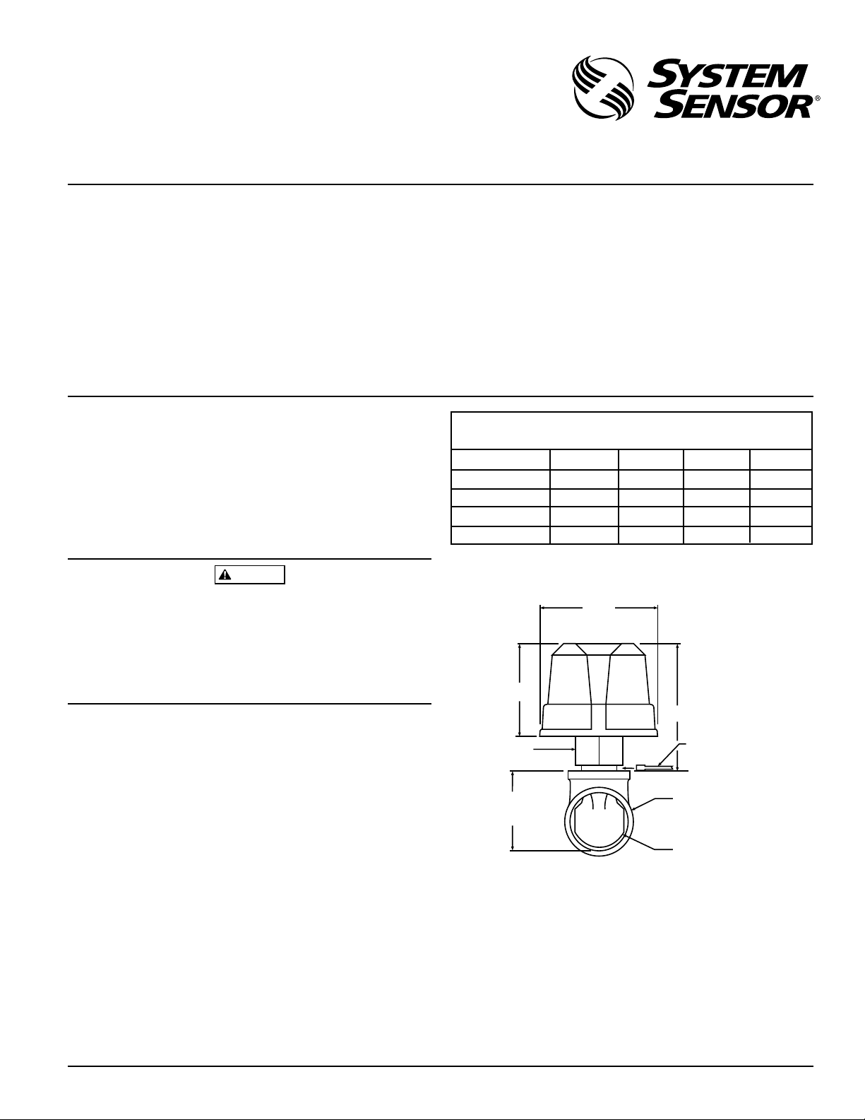
Specifications
Contact Ratings: 10 A @ 125/250 VAC
2.5 A @ 24 VDC
Triggering Threshold Bandwidth (Flow Rate): 4 to 10 gpm
Static Pressure Rating: 250 PSI (Max) 2" – 8"
Dimensions, Installed: 3.5"H x 3.0"W x 6.7"D
Operating Temperature Range: 32°F to 120°F (0°C to 49°C)
Compatible Pipe: Steel water pipe, schedule 10 or 40.
Shipping Weight: 4 to 7 lb., according to size.
Enclosure Rating: NEMA 4, as tested by Underwriters Laboratories, Inc.
(requires optional Outdoor Cover Gasket Model WFDN4 and cover part #C58-164-01)
Important
Please Read Carefully And Save
This instruction manual contains important information
about the installation and operation of waterflow detectors.
Purchasers who install waterflow detectors for use by others must leave this manual or a copy of it with the user.
Read all instructions carefully before beginning. Follow
only those instructions that apply to the model you are installing.
Principles Of Operation
Vane-type waterflow detectors mount to water-filled pipes
in sprinkler systems. Waterflow in the pipe deflects a vane,
which produces a switched output–usually after a specified
delay. All waterflow detectors have a pneumatically controlled mechanical delay mechanism. Delays do NOT accumulate; they reset if the flow of water stops before the
entire delay has elapsed. All switches actuate when the water flow rate is 10 gallons per minute or greater, but will not
actuate if the flow rate is less than 4 gallons per minute.
1-800-SENSOR2, FAX: 630-377-6495
A Division of Pittway
CAUTION
Use vane-type waterflow detectors in wet-pipe systems
only. Do NOT use them in dry pipe, deluge, or preaction
systems. The sudden inrush of water in such systems may
break the vane or damage the mechanism.
Do not use in potentially explosive atmospheres. Do not allow unused wires to remain exposed.
This System Sensor installation manual covers the following waterflow detectors for sprinkler/fire alarm applications.
Models
WFD20 Waterflow detector, Schedule 10/40, 2"
WFD25 Waterflow detector, Schedule 10/40, 2-1/2"
WFD30 Waterflow detector, Schedule 10/40, 3"
WFD35 Waterflow detector, Schedule 10/40, 3-1/2"
WFD40 Waterflow detector. Schedule 10/40, 4"
WFD50 Waterflow detector, Schedule 10/40, 5"
WFD60 Waterflow detector, Schedule 10/40, 6"
WFD80 Waterflow detector, Schedule 10/40, 8"
D770-01-00 1 I56-459-07
Technical Manuals Online! - http://www.tech-man.com
Page 2
CAUTION
Do NOT use any of the WFD models on copper pipe. The
clamping forces of the mounting bolts may collapse the
pipe sufficiently to prevent the detector from functioning
properly.
Do NOT install steel or iron pipe sections in copper piping
for mounting a waterflow detector. Incompatibility between the dissimilar metals causes bimetallic corrosion.
Installation Guidelines
Before installing any waterflow alarm device, be thoroughly familiar with:
NFPA 72: National Fire Alarm Code
NFPA 13: Installation of Sprinkler Systems, Section 3.17
NFPA 25: Inspection, Testing and Maintenance of Sprin-
kler Systems
Other applicable NFPA standards, local codes, and the requirements of the authority having jurisdiction
Failure to follow these directions may prevent the device
from reporting the flow of water in the event the associated
sprinkler system is activated by a fire. System Sensor is not
responsible for devices that have been improperly installed,
tested, or maintained.
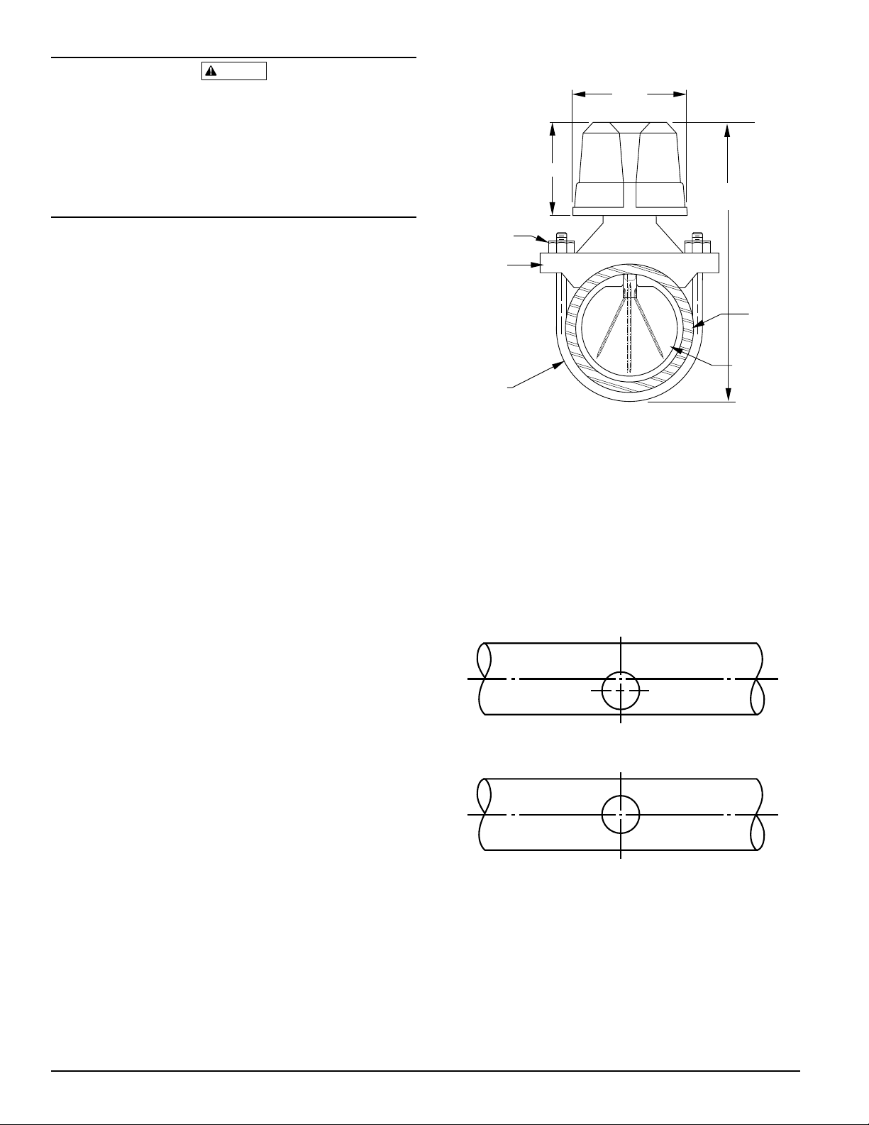
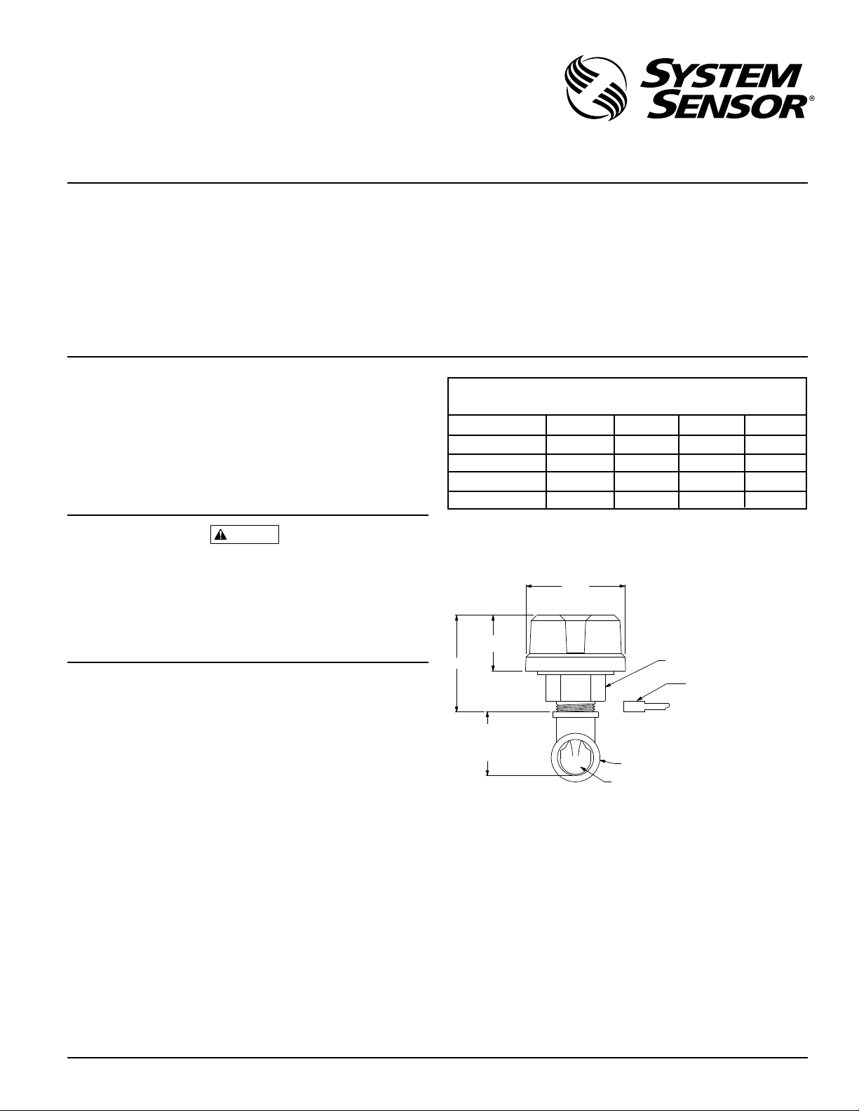
Figure 1. Mounting dimensions:
3-3/4"
3"
U-bolt nut
Pipe saddle
U-bolt
Overall width = pipe diameter + 3"
Pipe diameter
plus 5-1/4"
Pipe
Plastic vane
A78-1609-00
1. Mount the detector where there is adequate clearance for
installation and removal and a clear view of it for inspections. See Figure 1 for mounting dimensions.
2. Locate to protect from damage–6 to 7 feet above the
floor.
3. On horizontal runs, position the detector on the top or
side of the pipe. Do not mount it upside down because
condensation may collect in the housing and impair the
operation of the detector.
For vertical flow applications, mount the detector on
pipe through which water flows upward. Otherwise, the
unit may not operate properly.
4. Mount the detector at least 6 inches from a fitting that
changes the direction of water flow and no less than 24
inches from a valve or drain.
5. Be sure the direction-of-flow arrow matches the direction
of flow in the pipe.
Mounting Instructions
1. Drain the pipe.
2. Cut a hole at the desired location. Center the hole in the
pipe, as shown in Figure 2, and be sure the hole is perpendicular to the center of the pipe. Before drilling, use a
punch or scribe to mark the drill site to prevent the bit
from slipping. If the hole is off center, the vane will bind
against the inside wall of the pipe. Use a drill or hole
saw to cut a hole of the proper diameter. See Table 1 for
hole size.
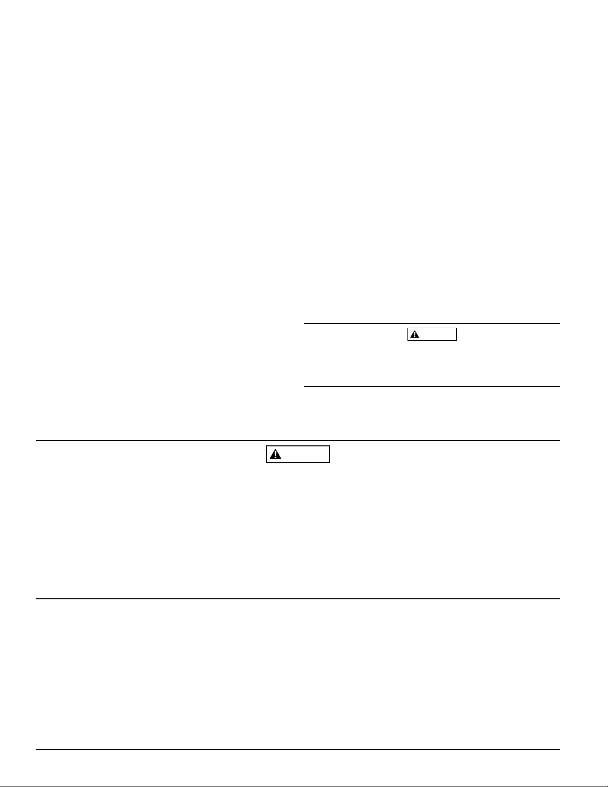
Figure 2. Mounting hole location:
Wrong
Right
Remove burrs from edge of hole. Clean out scale and foreign
matter for one pipe diameter on each side of hole.
A78-1496-01
D770-01-00 2 I56-459-07
Technical Manuals Online! - http://www.tech-man.com
Page 3
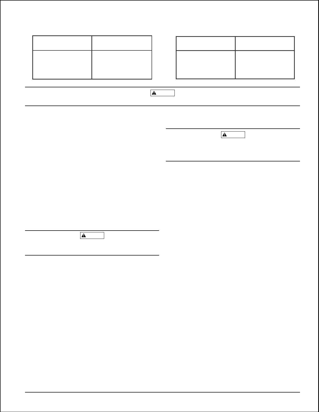
Table 2:Table 1:
WFD SIZE Hole Size
2" - 3-1/2
4" - 8
When drilling the hole with a hole saw, make certain that the center of the cut does not remain in the pipe.
3. Remove burrs and sharp edges from the hole. Clean and
remove all scale and foreign matter from the inside of
the pipe for one diameter on each side of the hole to ensure free movement of the vane. Clean the outside of the
pipe to remove dirt, metal chips, and cutting lubricant.
4. Seat the O-ring or gasket against the saddle and mount
the detector directly to the pipe. Carefully roll the vane
opposite the direction of flow and insert it through the
hole. Seat the saddle firmly against the pipe so that the
locating boss goes into the hole.
5. Install the U-bolt, tightening the nuts alternately to en-
sure a uniform seal. See Table 2 for torque values.
6. Remove the metal cover with the tamper-proof wrench
provided. Move the actuator lever back and forth to
check for binding. If the vane binds, remove the detector
and correct the cause before proceeding.
Be sure the direction-of-flow arrow points in the right direction or else water flow will go unreported. See Figure 3.
Preoperation Testing
1. Fill the sprinkler system and check for leaks around the
waterflow detector. If it leaks, first check for the proper
torque on the U-bolt nuts. If the leak persists, drain the
system and remove the detector (refer to Maintenance.
page 6). Check for dirt or foreign objects under the gasket, and make sure that the pipe surface is not dented.
Reinstall the detector and check again for leaks. Do not
proceed until all leaks have been stopped.
2. Connect an ohmmeter or continuity tester across the
COM and B switch terminals. The ohmmeter should indicate an open circuit.
3. Deflect the actuator lever and hold it until the pneumatic
delay shaft releases the switch buttons. The ohmmeter
or continuity tester should show a short circuit after the
delay has elapsed. If there is no delay, check the setting
of the delay adjustment dial.
"
"
CAUTION
1-1/4
2
"
"
CAUTION
Wiring
High Voltage. Electrocution Hazard. Do not handle live AC
wiring or work on a device to which AC power is applied.
Doing so may result in injury or death.
1. All models have two SPDT switches. Switch contacts
COM and B are closed when water is flowing and open
when it is not. Connect the switches, as shown in Figure
4 on page 5, depending on the application.
2. When connected to a listed sprinkler/fire alarm control
panel, the initiating circuit must be nonsilenceable.
3. A ground screw is provided with all waterflow detectors.
When grounding is required, clamp wire with screw in
hole located between conduit entrance holes. See Figure
5A, page 5.
4. If a second conduit entry is required, remove the knockout plug using a flat blade screwdriver as shown on Figure 5B, page 5. Strike sharply with a hammer to pierce
the wall of the knockout plug. Move to an adjacent wall
section and repeat until the plug falls out. Make sure
that the waterflow detector is supported adequately during this operation to avoid injury.
WFD SIZE Torque
2" - 3-1/2
4" - 8
"
"
WARNING
30 - 35 ft-lb
55 - 60 ft-lb
D770-01-00 3 I56-459-07
Technical Manuals Online! - http://www.tech-man.com
Page 4
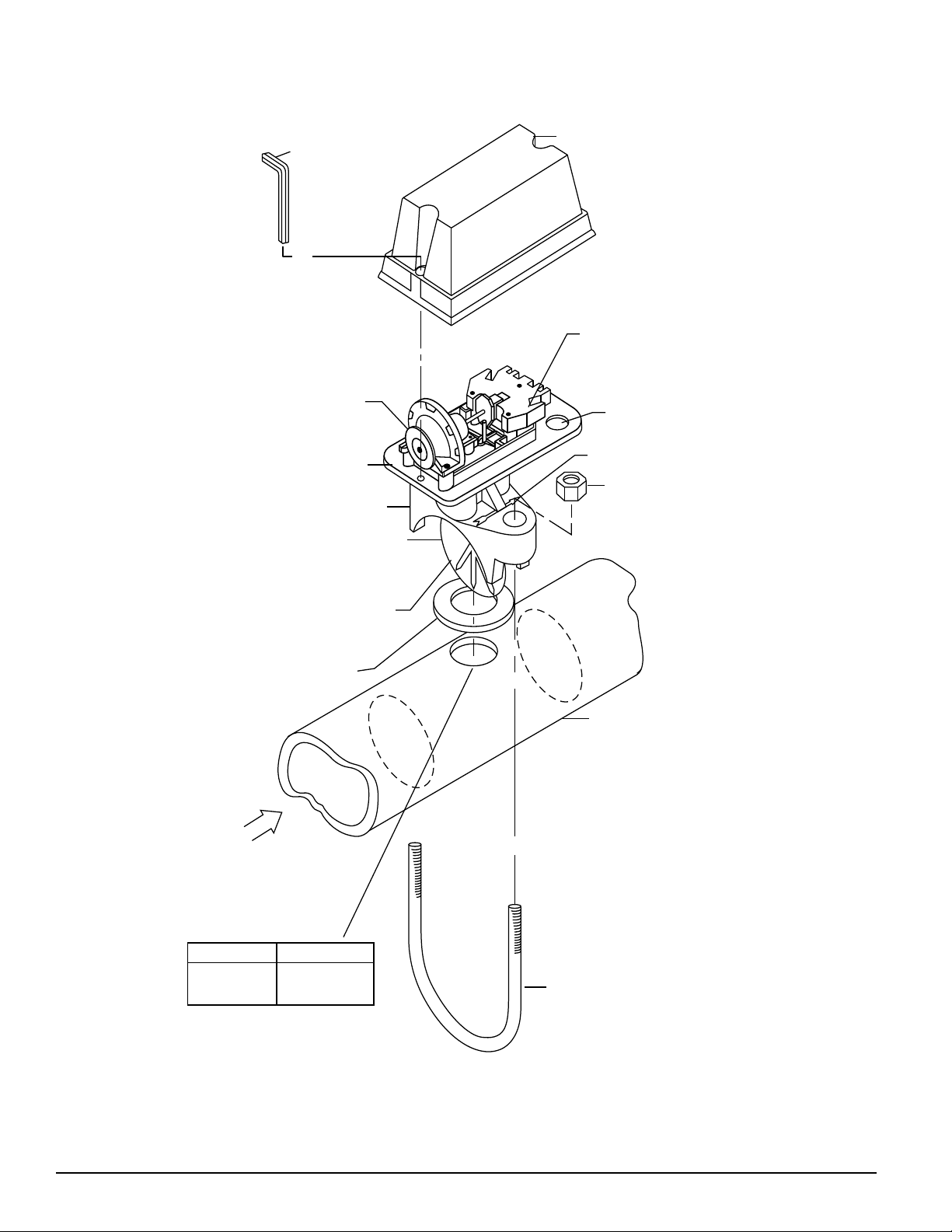
Figure 3. Assembly diagram:
Cover
Tamper proof wrench
(P/N WFDW)
Switch enclosure
(Replacement P/N A77-01-02)
Delay mechanism
(Replacement
P/N A3008-00)
Mounting plate
Pipe saddle
Roll paddle opposite
of flow arrow
while inserting
Saddle gasket
Plastic vane
Conduit entrance
Direction-of-flow arrow
U-bolt nut
Pipe
Waterflow
WFD Size
"
– 3-1/2"
2
4
"
– 8
D770-01-00 4 I56-459-07
"
Hole Size
1-1/4"
2
"
U-bolt
Technical Manuals Online! - http://www.tech-man.com
A78-1914-00
Page 5
Figure 4. WFD wiring:
WFD Switch
Assembly
Top View
to nonsilenceable initiating
zone of listed FACP
to power source
compatible
with bell
Switch 1
COM
ABBA
WFD
B
B
COM
COM
Typical FACP Connection
(Multiple Detectors)
B
COM
Typical Local Bell Connection
COM
local
bell
COM
B
NOTE: Common and B connections will
close when vane is deflected, i.e.,
when water is flowing. Dual switches
permit applications to be combined
on a single detector.
Switch 2
CONTACT RATINGS
125/250 VAC
24 VDC
WFD
B
end-of-line resistor
COM
Break wire as shown for
supervision of connection.
DO NOT allow stripped wire
leads to extend beyond
switch housing. Do NOT
loop wires.
10 AMPS
2.5 AMPS
Figure 5A. Ground screw location: Figure 5B. Knockout plug removal:
GROUND
SCREW
(GREEN)
MOUNTING
PLATE
A78-1586-00
A78-1914-03A78-2063-00
D770-01-00 5 I56-459-07
Technical Manuals Online! - http://www.tech-man.com
Page 6

Mechanical Delay Adjustment
The pneumatic delay is preset at the factory to dial setting
2. To adjust the setting, turn the adjustment dial clockwise
to increase the delay, counterclockwise to decrease it. The
delay is adjustable from 0 to 70 seconds. See Figure 6.
NOTE: Set the delay to the minimum required to prevent
false alarms from flow surges.
Maintenance
To prevent accidental water damage, control valves
should be shut tight and the system completely drained
before waterflow detectors are removed or replaced.
Inspect detectors monthly for leaks and replace if a leak
occurs. Test detectors at least monthly, as described under
Operational Testing, to ensure proper operation. Test more
often if required by the authority having jurisdiction.
After extended service, parts of the detector may become
worn, reducing the delay time and causing false alarms. If
this happens, increase the delay. If the delay is already at
the maximum, replace the mechanical delay assembly. Refer to Maintenance for ordering replacement parts.
Operational Testing
Always notify a central station monitoring waterflow
alarms before repairing, maintaining, or testing waterflow
alarm devices.
1. Replace the cover and tighten the tamper proof screws
with the tamper proof wrench. Store the wrench in a secure place.
2. Open the inspector’s test valve and time how long it
takes for the detector to indicate a flow condition. The
detector should remain activated until the inspector’s
test valve is closed. Air pockets in the sprinkler system
may increase the apparent delay.
Under normal conditions, System Sensor waterflow detectors should provide years of trouble-free service. However,
if the delay mechanism or switch enclosure becomes
faulty, replace it. To replace the delay mechanism or
switch enclosure, use a phillips head screwdriver to remove the three screws that hold it in place. Either mechanism can be easily replaced without removing the
detector from the pipe or draining the pipe. Do not repair
or replace any other waterflow detector components. If
any other part of the detector does not perform properly,
replace the entire detector. Failure to to follow this instruction may result in failure of the detector to report the
flow of water. To replace the delay mechanism, request
Part No. A3008-00. For switch enclosure, request Part No.
A77-01-02.
Figure 6. Delay adjustment dial:
Table of dial settings
embossed here.
See below.
ON
ER
DIAL
MB
NU
2
3
Delay adjustment dial
0
APP
0
ROX
IMA
1
15
TE
1
2
30
TIME
4
45
55
DEL
0
5
AY
70
(SE
CON
DS)
5
4
3
Dial setting
Seconds (±50%)
D770-01-00 6 I56-459-07
0
0
15
1
23
30
45
55
5
4
70
Technical Manuals Online! - http://www.tech-man.com
A78-1496-05
Page 7

To remove a detector:
1. Drain the pipe.
2. Turn off electrical power to the detector and disconnect
the wiring.
3. Loosen the nuts and remove the U-bolts.
4. Gently lift the saddle far enough to get your fingers un-
der it. Then, roll the vane so it will fit through the hole
while continuing to lift the waterflow detector saddle.
5. Lift the detector clear of the pipe.
CAUTION
If a vane breaks in a pipe, find and remove it. If it is not removed, the vane may restrict the flow of water to all or part
of the sprinkler system.
D770-01-00 7 I56-459-07
Technical Manuals Online! - http://www.tech-man.com
Page 8

The Limitations of Waterflow Alarm Devices
1. Waterflow detectors may not work or operate properly if
sprinkler piping being monitored is plugged with pipe
scale, mud, stones or other foreign material. Sprinkler
systems should be checked regularly for such blocking
material, following the instructions in Chapter 5 of NFPA
Standard 13A.
2. Alarms generated by the activation of waterflow detectors may not be received by a central station if telephone
or other communication lines to the detector are out of
service, disabled, or open.
3. Vane-type waterflow detectors have a normal service life
Three-Year Limited Warranty
System Sensor warrants its enclosed waterflow detector to be free from defects in materials and workmanship under normal use and service for a
period of three years from date of manufacture. System Sensor makes no
other express warranty for this waterflow detector. No agent, representative, dealer, or employee of the Company has the authority to increase or
alter the obligations or limitations of this Warranty. The Company’s obligation of this Warranty shall be limited to the repair or replacement of any
part of the waterflow detector which is found to be defective in materials
or workmanship under normal use and service during the three year period commencing with the date of manufacture. After phoning System
Sensor’s toll free number 800-SENSOR2 (736-7672) for a Return Authorization number, send defective units postage prepaid to: System Sensor,
WARNING
of 10-15 years. Hard water systems, however, may reduce waterflow detector service life to 4 or 5 years.
4. Waterflow detectors are not a substitute for insurance.
Building owners should always insure property and lives
being protected by sprinkler systems.
5. If valves controlling the water supply to a sprinkler system are closed, vane-type waterflow detectors will not
work. All valves controlling a sprinkler water supply
should be sealed or locked in the normally open position. The normally open position should be monitored
by a sprinkler supervisory switch.
Repair Department, RA #__________, 3825 Ohio Avenue, St. Charles, IL
60174. Please include a note describing the malfunction and suspected
cause of failure. The Company shall not be obligated to repair or replace
units which are found to be defective because of damage, unreasonable
use, modifications, or alterations occurring after the date of manufacture.
In no case shall the Company be liable for any consequential or incidental
damages for breach of this or any other Warranty, expressed or implied
whatsoever, even if the loss or damage is caused by the Company’s negligence or fault. Some states do not allow the exclusion or limitation of incidental or consequential damages, so the above limitation or exclusion may
not apply to you. This Warranty gives you specific legal rights, and you
may also have other rights which vary from state to state.
D770-01-00 8 I56-459-07
Technical Manuals Online! - http://www.tech-man.com
© System Sensor 1996
Page 9
INSTALLATION AND MAINTENANCE INSTRUCTIONS
WFDT/WFDTH Vane-type
Waterflow Detectors
3825 Ohio Avenue, St. Charles, Illinois 60174
1-800-SENSOR2, FAX: 630-377-6495
A Division of Pittway
Specifications
Contact Ratings: Two sets of SPDT (Form C)
10 A @ 125/250 VAC; 2.5 A @ 24 VDC
Triggering Threshold Bandwidth (Flow Rate): 4 - 10 GPM
Service Pressure Rating: 250 PSI (Max.)
Overall Dimensions, Installed: WFDT– 45/16
WFDTH– 45/16
″
H × 3
″
H × 3
3
/4
″
9
/16
W × 6
″
W × 6
3
/4″D
3
/4″D
Operating Temperature Ranges: 32°F - 120°F (0°C - 49°C)
Shipping Weight: 2.6 lbs.
The WFDT is U.L. listed for indoor and outdoor installations
The WFDTH is U.L. listed for indoor use only. The WFDTH can be installed between 2×4 stud wall construction.
Important
Please Read Carefully And Save
This instruction manual contains important information
about the installation and operation of waterflow detectors.
Purchasers who install waterflow detectors for use by
others must leave this manual or a copy of it with the user.
Read all instructions carefully before beginning.
Tee Depth Threaded Sweat Poly B CPVC
1 × 1 × 1″
11/4 × 11/4 × 1″
11/2 × 11/2 × 1″
2 × 2 × 1"
Approximate Tee Depth Requirements
(See Figure 1)
21/8″
21/2″
23/4″
13/4″ N/A 21/4″
21/6″ N/A
21/4″
21/2″
N/A 23/4″
N/A
N/A
N/AN/A
CAUTION
Use vane-type waterflow detectors in wet-pipe systems
only. DO NOT USE IN DRY-PIPE, DELUGE, OR PRE-ACTION SYSTEMS. The sudden inrush of water in such systems may break the vane off or damage the mechanism. Do
not use in potentially explosive atmospheres. Do not leave
unused wires exposed.
Principles Of Operation
Vane-type waterflow detectors mount to water filled pipes
in sprinkler systems. Water flow in the pipe deflects a vane.
Deflection of the vane produces a switched output, usually
after a specified delay.
All WFDTs have a pneumatically controlled mechanical
delay mechanism. Delays are noncumulative; they reset if
the flow of water stops before the entire delay has elapsed.
All detectors will activate on a sustained flow of water
greater than 10 gallons per minute (gpm) but will not
activate if the flow rate is less than 4 gpm.
Compatible Pipe Tees
The WFDT and WFDTH fit 1″ to 11/2″ NPT threaded ferrous
and brass, 1″ to 2″ sweat brass, 11/2″ polybutylene plastic
and 1″ pvc plastic tees having a 1″ threaded NPT branch
(see Figure 1 and chart for recommended tee depths).
Figure 1. Mounting dimensions:
33/4″
(WFDT)
39/16″
(WFDTH)
3″
45/16″
Tee Adapter
Tee Depth
Refer to
Tee Depth
Table
Gage (End of Paddle Tree)
Must Fit Between Top of
Tee and Bottom of Flange
Tee Fitting
Plastic Vane
A78-1939-00
Installation Guidelines
Before installing any waterflow alarm device, be
thoroughly familiar with:
NFPA 72: National Fire Alarm Code
NFPA 13: Installation of Sprinkler Systems
NFPA 25: Inspection, Testing, and Maintenance of
Water-based Fire Protection Systems
NFPA 13D: Standard for 1 and 2 Family Dwellings and
Manufactured Homes
NFPA 13R: Standard for Multi-family Dwellings
N770-05-00 1 I56-480-03
Technical Manuals Online! - http://www.tech-man.com
Page 10
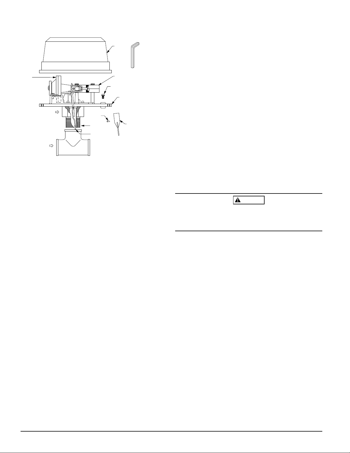
Figure 2. Assembly diagram:
COVER
TAMPER PROOF
WRENCH (P/N WFDW)
DELAY
MECHANISM
(REPLACEMENT
P/N A3008-00)
WATERFLOW
FLOW
FILLISTER
HEAD SCREW
1″ NPT THREAD
ACTUATOR
LEVER
SWITCH ENCLOSURE
(REPLACEMENT
P/N A77-01-02)
GROUND
SCREW
(GREEN)
MOUNTING
PLATE
PADDLE
(PADDLE
REPLACEMENT
KIT (P/N PRK9)
A78-2134-01
(Cover tamper option is available.)
Also, follow other applicable NFPA standards, local codes
and the requirements of the authority having jurisdiction.
Failure to follow these directions may result in failure of the
device to report a waterflow condition. System Sensor is
not responsible for devices that have been improperly
installed, tested or maintained.
1. Mount the detector where there is adequate clearance
for installation and removal and a clear view of it for inspection. See Figure 1 for mounting dimensions.
2. Locate to protect from damage, 6-7 feet above the floor.
3. On horizontal runs, position the detector on top of the
pipe or on the side of it. Do not mount it upside down
because condensation may collect in the housing and
impair the operation of the detector.
For vertical flow applications, mount detector on pipe
where upflow conditions exist. Failure to do so may prevent unit from operating properly.
4. Mount detector at least 6 inches from a fitting which
changes the direction of the water flow, or no closer than
24 inches from a valve or drain.
5. BE SURE DIRECTION-OF-FLOW ARROW MATCHES ACTUAL DIRECTION OF FLOW IN THE PIPE.
Mounting Instructions
1. The WFDT and WFDTH waterflow detectors are designed to fit only the appropriate tee fitting.
2. WFDT and WFDTH units are shipped without paddles
mounted to the actuator. Select the correct size paddle
for the type of tee being used. Align hole on stem of
paddle with hole on actuator lever. Fasten together using
a #4-40 x 1/4" fillister head screw supplied in bag assembly. See Figure 2. Use only the screw provided with
the unit. Drive screw head through hole in paddle until
it seats to actuator lever surface. No washer is required.
For paddle replacement refer to Maintenance section.
3. Carefully roll the vane opposite the direction of flow and
insert through tee. Thread detector onto tee fitting and
tighten with wrench. Use of thread sealant or tape is recommended. Use height gage (located at end of paddle
tee) to ensure proper depth of detector on tee fitting. See
Figure 1. Height gage must fit between top of tee fitting
and under side of hex tee adapter. A gap between gage
and tee adapter is acceptable. When correctly installed,
the detector must face in the proper direction of
waterflow and be aligned with the pipe.
4. Remove the metal cover. Move the actuator lever back
and forth to check for binding. If the vane binds, remove
the detector and correct the problem before proceeding.
CAUTION
Be sure the direction-of-flow arrow points in the right direction, otherwise a waterflow condition will go unreported.
See Figure 2.
Preoperation Testing
1. Fill the sprinkler system with water and check for leaks
around the WFDT or WFDTH. If there is a leak, check to
see that the fittings are tight. If leak persists, drain the
system and remove the detector (see removal instructions under Maintenance). Check for damaged threads
or cracked fitting. Reinstall the detector and check again
for leaks. Do not proceed until all leaks have been
stopped.
2. Connect an ohmmeter or continuity tester across (COM
and B) terminal switch contacts. The ohmmeter should
show an open circuit, no continuity.
3. Deflect the actuator lever and hold it until the pneumatic
delay shaft releases the switch buttons. The ohmmeter
or continuity tester should show a short circuit after the
delay has elapsed. If there is no delay, check the setting
of the delay adjustment dial.
NOTE: Leg of tee perpendicular to flow of water must
have a 1" NPT thread. Do not use a reducer to
achieve the correct thread size. Failure to follow
this instruction will result in failure of the detector
to report a waterflow condition.
N770-05-00 2 I56-480-03
Technical Manuals Online! - http://www.tech-man.com
Page 11
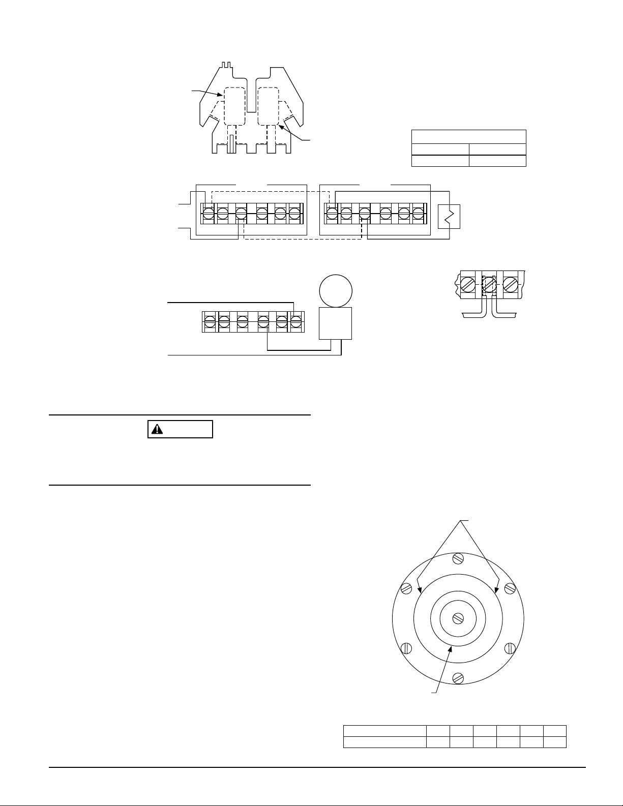
Figure 3. Field wiring:
Switch 1
COM
Top Vie w
NOTE: Common and B connections will
close when vane is deflected, i.e.,
when water is flowing. Dual switches
permit applications to be combined
on a single detector.
COM
ABBA
WFDTH
WFDT
BB
to nonsilenceable initiating
zone of listed FACP
to power source
compatible
with bell
COM COM
Typical FACP Connection
B
COM
Typical Local Bell Connection
Field Wiring
WARNING
High Voltage. Electrocution Hazard. Do not handle live AC
wiring or work on a device to which AC power is applied.
Doing so may result in severe injury or death.
Switch 2
WFDTH
WFDT
BB
COM COM
local
bell
WFDT and WFDTH
switch assembly
CONTACT RATINGS
125/250 VA C
24 VDC
Break wire as shown for
supervision of connection.
DO NOT allow stripped wire
leads to extend beyond
switch housing. DO NOT
loop wires.
10 AMPS
2.5 AMPS
end-of-line resistor
A78-1992-00
After extended service, parts of the detector may become
worn reducing the delay time and causing false alarms. If
this happens, increase the delay. If the delay is already at
maximum, replace the mechanical delay assembly. Refer to
Maintenance section for ordering replacement parts.
1. The WFDT and WFDTH have two SPDT switches. Switch
contacts (COM and B) are closed when water is flowing
and open when water is not flowing. Connect the switches
as shown in Figure 3 depending on the application.
2. When connected to a listed sprinkler/fire alarm control
panel, the initiating circuit must be non-silenceable.
3. A ground screw is provided with all units. When grounding is required, clamp wire with screw in hole located
between conduit entrance holes. See Figure 2.
Mechanical Delay Adjustment
The pneumatic delay is preset at dial setting 2 at the
factory. To adjust the delay, turn the adjustment dial on the
delay mechanism. Turn clockwise to increase the delay,
counterclockwise to decrease the delay. Delay can be
adjusted over a range from 0-70 seconds. See Figure 4.
NOTE: Set the delay to the minimum required to prevent
false alarms due to flow surges.
N770-05-00 3 I56-480-03
Technical Manuals Online! - http://www.tech-man.com
Figure 4. Delay adjustment dial:
Table of dial settings
3
2
45
1
30
0
15
0
1
0
2
3
Delay adjustment dial
Dial setting
Seconds (±50%)
001152303454555
embossed here.
See below.
4
55
5
70
5
4
70
A78-1596-05
Page 12
Operational Testing
Always notify a central station monitoring waterflow
alarms before repairing, maintaining or testing waterflow
alarm devices.
1. Replace the cover and tighten the security screws with
the tamper proof wrench. Store the wrench in a secure
place.
2. Open the inspector’s test valve and time how long it
takes for the detector to indicate a flow condition. The
detector should remain activated until the inspector’s
test valve is closed. Air pockets in the sprinkler system
may increase the apparent time delay.
Maintenance
To prevent accidental water damage, control valves should
be shut tightly and the system completely drained before
waterflow detectors are removed or replaced.
Inspect detectors monthly for leaks. Test detectors at least
monthly as described under Operational Testing above to
insure proper operation. This device is not designed for use
on “dry pipe” systems. Test more often if required by the
authority having jurisdiction.
replacement kits are available. To replace the delay
mechanism, request Part No. A3008-00; for switch
enclosure, request Part No. A77-01-02. Complete
instructions are enclosed with each. Either mechanism can
be easily replaced without removing the detector from the
pipe or draining the pipe. If damage occurs to paddle, order
replacement kit PRK9. Refer to procedure below for
removal of detector on pipe. Do not repair or replace any
other waterflow detector components in the field. If any
other part of the detector does not perform properly,
replace the entire detector. Failure to follow this
instruction may result in failure of the detector to report
a waterflow condition.
Proceed as follows to remove a detector.
1. Drain the pipe.
2. Turn off electrical power to the detector, and then disconnect wiring.
3. Unscrew WFDT or WFDTH from tee fitting.
4. Lift detector clear of pipe.
CAUTION
Under normal conditions System Sensor waterflow
detectors should provide years of trouble-free service. If,
however, the delay mechanism becomes faulty,
WARNING
The Limitations of Waterflow Alarm Devices
1. Waterflow detectors may not work or operate properly if
sprinkler piping being monitored is plugged with pipe
scale, mud, stones or other foreign material. Sprinkler
systems should be checked regularly for such blocking
material, following the instructions in NFPA Standard 25.
2. Alarms generated by the activation of waterflow detectors may not be received by a central station if telephone
or other communication lines to the detector are out of
service, disabled, or open.
Three-Year Limited Warranty
System Sensor warrants its enclosed waterflow detector to be free from defects in materials and workmanship under normal use and service for a
period of three years from date of manufacture. System Sensor makes no
other express warranty for this waterflow detector. No agent, representative, dealer, or employee of the Company has the authority to increase or
alter the obligations or limitations of this Warranty. The Company’s obligation of this Warranty shall be limited to the repair or replacement of any
part of the waterflow detector which is found to be defective in materials
or workmanship under normal use and service during the three year period commencing with the date of manufacture. After phoning System
Sensor’s toll free number 800-SENSOR2 (736-7672) for a Return Authorization number, send defective units postage prepaid to: System Sensor,
If a vane breaks off in a pipe, find and remove it. Failure to
do so may restrict the proper flow of water to part of the
sprinkler system.
3. Vane-type waterflow detectors have a normal service life
of 10-15 years. Hard water systems, however, may reduce waterflow detector service life to 4 or 5 years.
4. If valves controlling the water supply to a sprinkler system are closed, vane-type waterflow detectors will not
work. All valves controlling a sprinkler water supply
should be sealed or locked in the normally open position. The normally open position should be monitored
by a sprinkler supervisory switch.
Repair Department, RA #__________, 3825 Ohio Avenue, St. Charles, IL
60174. Please include a note describing the malfunction and suspected
cause of failure. The Company shall not be obligated to repair or replace
units which are found to be defective because of damage, unreasonable
use, modifications, or alterations occurring after the date of manufacture.
In no case shall the Company be liable for any consequential or incidental
damages for breach of this or any other Warranty, expressed or implied
whatsoever, even if the loss or damage is caused by the Company’s negligence or fault. Some states do not allow the exclusion or limitation of incidental or consequential damages, so the above limitation or exclusion may
not apply to you. This Warranty gives you specific legal rights, and you
may also have other rights which vary from state to state.
N770-05-00 4 I56-480-03
Technical Manuals Online! - http://www.tech-man.com
© System Sensor 1996
Page 13
INSTALLATION AND MAINTENANCE INSTRUCTIONS
WFDTNR Vane-type
Waterflow Detector
Specifications
Contact Ratings: 10 A @ 125/250 VAC
2.5 A @ 24 VDC
Triggering Threshold Bandwidth (Flow Rate): 4 - 10 GPM
Static Pressure Rating: 250 PSI (Max.)
Overall Dimensions, Installed: 3.25" x 4.25" cover dia.
3.25" above pipe tee
Operating Temperature Range: 32°F - 120°F (0°C - 49°C)
Shipping Weight: 1.5 lbs.
Important
Please Read Carefully And Save
This instruction manual contains important information
about the installation and operation of waterflow detectors.
Purchasers who install waterflow detectors for use by others must leave this manual or a copy of it with the user.
Read all instructions carefully before beginning.
CAUTION
Tee Depth Threaded Sweat Poly B CPVC
1 × 1 × 1″
11/4 × 11/4 × 1″
11/2 × 11/2 × 1″
2 × 2 × 1"
A Division of Pittway
3825 Ohio Avenue, St. Charles, Illinois 60174
1-800-SENSOR2, FAX: 630-377-6495
Approximate Tee Depth Requirements
(See Figure 1)
21/8″
21/2″
23/4″
13/4″ N/A 21/4″
21/6″ N/A
21/4″
21/2″
N/A 23/4″
N/A
N/A
N/AN/A
Use vane-type waterflow detectors in wet-pipe systems
only. DO NOT USE IN DRY-PIPE, DELUGE, OR PRE-ACTION SYSTEMS. The sudden inrush of water in such systems may break the vane off or damage the mechanism. Do
not use in potentially explosive atmospheres. Do not leave
unused wires exposed.
Principles Of Operation
Vane-type waterflow detectors mount to wet-pipe systems
only. Water flow in the pipe deflects a vane. Deflection of
the vane produces a switched output. All detectors will activate on a sustained flow of water greater than 10 gallons
per minute (gpm) but will not activate if the flow rate is
less than 4 gpm.
Compatible Pipe Tees
Model WFDTNR fits 1"–11/2" NPT threaded ferrous and
brass, 1" - 2" sweat brass, 11/2" polybutylene plastic and 1"
pvc plastic tees having a 1" threaded NPT branch (see Figure 1 and chart for recommended tee depths).
Installation Guidelines
Before installing any waterflow alarm device, be thoroughly familiar with:
NFPA 72: Installation, Maintenance and Use of Local
Protective Signalling Systems
Figure 1. Mounting dimensions:
3 1/4"
1 3/4"
3 1/4"
"TEE DEPTH"
REFER TO
TEE DEPTH
TABLE
PIPE TEE FITTING
PLASTIC VANE
HEX TEE ADAPTOR
INSTALLATION GAGE
(END OF PADDLE TREE)
MUST FIT BETWEEN TOP
OF TEE AND BOTTOM OF
HEX TEE ADAPTOR FLANGE.
A78-2110-00
NFPA 13: Installation of Sprinkler Systems, specifically
Section 3.17
NFPA 25: Inspection, Testing and Maintenance of Sprin-
kler Systems, specifically Chapters 4 and 5
NFPA 13D: Standard for Residential Dwellings
NFPA 13R: Standard for Multifamily Dwellings
Other applicable NFPA standards, local codes and the requirements of the authority having jurisdiction.
Failure to follow these directions may result in failure of the
device to report a waterflow condition. System Sensor is
N770-06-00 1 I56-509-01
Technical Manuals Online! - http://www.tech-man.com
Page 14

Figure 2. Assembly diagram:
COVER
TAMPER PROOF
WRENCH (P/N WFDW)
PADDLE
A78-2111-00
ACTUATOR
LEVER
FLOW
ACTUATOR
ASSEMBLY
HEAD SCREW
WATER FLOW
FILLISTER
1" NPT THREAD
GROUND
SCREW
(GREEN)
MOUNTING
PLATE
not responsible for devices that have been improperly installed, tested or maintained.
1. Mount the detector where there is adequate clearance
for installation and removal and a clear view of it for inspection. See Figure 1 for mounting dimensions.
2. Locate to protect from damage, 6-7 feet above the floor.
3. On horizontal runs, position the detector on top of the
pipe or on the side. Do not mount it upside down.
4. Mount detector at least 6 inches from a fitting which
changes the direction of the water flow.
5. BE SURE DIRECTION-OF-FLOW ARROW MATCHES ACTUAL DIRECTION OF FLOW IN THE PIPE.
Mounting Instructions
1. This WFDTNR waterflow detector is designed to fit only
the appropriate tee fitting.
NOTE: Leg of tee perpendicular to flow of water must
have a 1" NPT thread. Do not use a reducer to
achieve the correct thread size. Failure to follow
this instruction will result in failure of the detector
to report a waterflow condition.
2. WFDT units are shipped without the paddles mounted to
the actuator. Select the correct size paddle for the tee being used the appropriate nominal pipe diameter size is
molded on the surface of the paddles). Align hole on
stem of paddle with hole on actuator lever. Fasten together using a #4-40 x 1/4" fillister head screw supplied
in bag assembly. See Figure 2. Use only the screw provided with the WFDTNR. Drive screw head through hole
in paddle until it seats firmly to actuator lever surface.
No washer is required. For paddle replacement refer to
Maintenance section.
3. Thread detector onto tee fitting and tighten with
wrench. Use of thread sealant or tape is recommended.
Use height gage (located at end of paddle tee) to ensure
proper depth of detector on tee fitting. See Figure 1.
Height gage must fit between top of tee fitting and under
side of hex tee adapter. A gap between gage and tee
adapter is acceptable. When correctly installed, the detector must face in the proper direction of waterflow and
be aligned with the pipe.
4. Remove the plastic cover with the tamper proof wrench
provided. Move the actuator lever back and forth to
check for binding. If the vane binds, remove the detector
and correct the problem before proceeding.
CAUTION
Be sure the direction-of-flow arrow points in the correct direction, otherwise a waterflow condition will go unreported. See Figure 2.
Operational Testing
Always notify a central station monitoring waterflow
alarms before repairing, maintaining, or testing waterflow
alarm devices.
1. Fill the sprinkler and check for leaks around the
WFDTNR. If it leaks, check to see that the fittings are
tight. If leak persists, drain the system and remove the
detector (see removal instructions under Maintenance).
Check for damaged threads or cracked fitting. Reinstall
detector and check again for leaks. Do not proceed until
all leaks have been stopped.
2. With cover removed, connect an ohmmeter or continuity tester across (COM and B) terminal switch contacts.
The ohmmeter should show an open circuit, no continuity (when the red switch buttons are depressed).
3. Deflect the actuator lever to release the switch buttons.
The ohmmeter or continuity tester should show a short
circuit when the switch buttons are released.
4. Open the inspector's test valve to allow the detector to
indicate a flow condition. The detector should remain
activated until the inspector's test valve is closed. Air
pockets in the sprinkler system may prevent the detector
from firing immediately.
5. Replace the cover and tighten the security screws with
the tamper proof wrench. Store wrench is a secure place.
Field Wiring
1. The WFDT has two SPDT switches. Switch contacts
(COM and B) are closed when water is flowing and open
when water is not flowing. Connect the switches as
shown in Figure 3 depending on the application.
2. When connected to a listed sprinkler/fire alarm control
panel, the initiating circuit must be non-silenceable.
N770-06-00 2 I56-509-01
Technical Manuals Online! - http://www.tech-man.com
Page 15

Figure 3. Field wiring:
Switch 1
COM
COM
NOTE: Common and B connections will
close when vane is deflected, i.e.,
when water is flowing. Dual switches
permit applications to be combined
on a single detector.
Strip Gauge
to nonsilenceable initiating
zone of listed FACP
to power source
compatible
with bell
ABBA
WFDTNR
BB
COM COM
Typical FACP Connection
B
Typical Local Bell Connection
Switch 2
COM
3. A ground screw is provided with all WFDT units. When
grounding is required, clamp wire with screw in hole located between conduit entrance holes. See Figure 2.
WARNING
High Voltage. Electrocution Hazard. Do not handle live AC
wiring or work on a device to which AC power is applied.
Doing so may result in severe injury or death.
Maintenance
To prevent accidental water damage, control valves should
be shut tightly and the system completely drained before
waterflow detectors are removed or replaced.
Inspect detectors monthly for leaks. Test detectors at least
monthly as described under Operational Testing to insure
proper operation. This device is not designed for use on
“dry pipe” systems. Test more often if required by the authority having jurisdiction.
CONTACT RATINGS
WFDTNR
BB
COM COM
local
bell
125/250 VAC
24 VDC
Break wire as shown for
supervision of connection.
DO NOT allow stripped wire
leads to extend beyond
switch housing. DO NOT
loop wires.
10 AMPS
2.5 AMPS
end-of-line resistor
Under normal conditions System Sensor waterflow detectors should provide years of trouble-free service. If, however, the switch enclosure becomes faulty, request Part No.
A77-01-08. If damage occurs to paddle, order replacement
kit PRK9. Refer to procedure below for removal of detector
on pipe. Do not repair or replace any other waterflow detector components in the field. If any other part of the detector does not perform properly, replace the entire
detector. Failure to follow this instruction may result in
failure of the detector to report a waterflow condition.
Proceed as follows to remove a detector:
1. Drain the pipe
2. Turn off electrical power to the detector, and then disconnect wiring
3. Unscrew WFDTNR from tee fitting
N770-06-00 3 I56-509-01
Technical Manuals Online! - http://www.tech-man.com
Page 16

WARNING
The Limitations of Waterflow Alarm Devices
1. Waterflow detectors may not work or operate properly if
sprinkler piping being monitored is plugged with pipe
scale, mud, stones or other foreign material. Sprinkler
systems should be checked regularly for such blocking
material, following the instructions in Chapter 5 of NFPA
Standard 13A.
2. Alarms generated by the activation of waterflow detectors may not be received by a central station if telephone
or other communication lines to the detector are out of
service, disabled, or open.
3. Vane-type waterflow detectors have a normal service life
Three-Year Limited Warranty
System Sensor warrants its enclosed waterflow detector to be free from defects in materials and workmanship under normal use and service for a
period of three years from date of manufacture. System Sensor makes no
other express warranty for this waterflow detector. No agent, representative, dealer, or employee of the Company has the authority to increase or
alter the obligations or limitations of this Warranty. The Company’s obligation of this Warranty shall be limited to the repair or replacement of any
part of the waterflow detector which is found to be defective in materials
or workmanship under normal use and service during the three year period commencing with the date of manufacture. After phoning System
Sensor’s toll free number 800-SENSOR2 (736-7672) for a Return Authorization number, send defective units postage prepaid to: System Sensor,
of 10-15 years. Hard water systems, however, may reduce waterflow detector service life to 4 or 5 years.
4. Waterflow detectors are not a substitute for insurance.
Building owners should always insure property and lives
being protected by sprinkler systems.
5. If valves controlling the water supply to a sprinkler system are closed, vane-type waterflow detectors will not
work. All valves controlling a sprinkler water supply
should be sealed or locked in the normally open position. The normally open position should be monitored
by a sprinkler supervisory switch.
Repair Department, RA #__________, 3825 Ohio Avenue, St. Charles, IL
60174. Please include a note describing the malfunction and suspected
cause of failure. The Company shall not be obligated to repair or replace
units which are found to be defective because of damage, unreasonable
use, modifications, or alterations occurring after the date of manufacture.
In no case shall the Company be liable for any consequential or incidental
damages for breach of this or any other Warranty, expressed or implied
whatsoever, even if the loss or damage is caused by the Company’s negligence or fault. Some states do not allow the exclusion or limitation of incidental or consequential damages, so the above limitation or exclusion may
not apply to you. This Warranty gives you specific legal rights, and you
may also have other rights which vary from state to state.
N770-06-00 4 I56-509-01
Technical Manuals Online! - http://www.tech-man.com
© System Sensor 1996
Page 17

INSTALLATION AND MAINTENANCE INSTRUCTIONS
OSY2 Gate Valve
Supervisory Switch
Specifications
Contact Ratings: 10 A @ 125/250 VAC
2.5 A @ 24 VDC
Dimensions: 53/4"H X 31/2"W X 31/4"L
Maximum Stem Extension: 25/8"
Minimum Stem Extension:
Bracket Span: 63/4"
Operating Temperature Range: 32° - 120°F (0° - 49°C)
Shipping Weight: 23/4 lb.
Important
Please Read Carefully And Save
This manual contains important information about the installation and operation of supervisory switches. These instructions apply to System Sensor switches for outside
screw and yoke valves only. Read all instructions carefully
before beginning installation.
WARNING
Do NOT use this switch in explosive or potentially explosive atmospheres.
Do NOT leave unused wires exposed.
5
/8"
A Division of Pittway
3825 Ohio Avenue, St. Charles, Illinois 60174
1-800-SENSOR2, FAX: 630-377-6495
Figure 1:
ACTUATOR
VERTICAL (DOWN)
ACTUATOR
HORIZONTAL
ment. If this is the case, the bolts can be positioned on the
outside of the yoke.
All supervisory switch installations must comply with local
codes and ordinances and the requirements of the authority
having jurisdiction. Additional information is available in
National Fire Protection Association standards NFPA 13,
13D, 13R, 71, and 72.
General Installation Considerations
The OSY2 Supervisory Switch can be mounted on open
yoke valves between 1/2" and 12" in diameter in the positions shown in Figure 1 only. If the switch is installed with
the actuator pointing upward, water may leak into the interior of the switch. Therefore, do NOT install the OSY2
with its actuating lever pointing upward.
All OSY2 models are equipped with a ground screw inside
the switch housing near the conduit exit hole for those applications where grounding is required.
Narrow Yoke Valves
As Figure 2 suggests, installing the valve with mounting
bolts inside the yoke is recommended. However, some
valves may have yokes that are too narrow for this arrange-
Limited Clearance Valves
The OSY2 mounting bracket fits most of the open yoke
valves used in fire protection systems. However, some of
these valves, especially those less than 11/2" in diameter,
have irregularly shaped yokes or such limited clearances
that the clamping bar cannot be installed properly and/or it
causes the valve to bind. If this is the case, the use of the
supplied J-bolts is required to attach the OSY2 to the valve
(see J-Bolt Detail, Figure 2).
Installation Procedure
See Figures 2 and 3, as required, while performing the procedure that follows.
Perform step 1 on valves 11/2" in diameter and smaller
only. Proceed directly to step 2 if the switch is being installed on a valve larger than 11/2" in diameter.
1. Remove and discard the two C-clips and roller from the
actuating lever.
2. Set the valve to its fully open position. Remove the OSY2
Supervisory Switch from the carton and adjust the position of the retaining washers to provide sufficient bolt
length for the yoke thickness of the valve.
N770-04-00 1 I56-393-05
Technical Manuals Online! - http://www.tech-man.com
Page 18

Figure 2:
Actuating Cam
Actuating lever
set screw
Wrench for
tamper-resistant
screws
(P/N WFDW)
Cover
Spring
Mounting screws
Terminal block
Tamper-resistant
screws
Seal
Base housing
Mounting Bracket
"C" clip
Actuating lever roller
(2 thru 12"only)
Valve Stem
Carriage Bolt
Yoke
Clamping Bar
J-Bolt Detail
Hex wrench
(P/N HEXW)
SLIDE CLAMPING
BAR TO REMOVE
OR INSTALL.
NOTE:
LARGER GATE VALVE SHOWN (2" THRU 12"). WHEN INSTALLING
SUPERVISORY SWITCH TO SMALLER GATE VALVES (1/2" THRU 1 1/2")
CARRIAGE BOLTS ARE TO BE LOCATED ON OUTBOARD SIDE OF YOKE.
ON SMALL VALVES WITH LIMITED CLEARANCE THE USE OF J-BOLTS
MAY BE REQUIRED.
Retaining Washer
Nut
N770-04-00 2 I56-393-05
Technical Manuals Online! - http://www.tech-man.com
Page 19

Figure 3: the valve, slide the open end of the clamping bar onto
the bolts and under the retaining washers, as indicated
in Figure 2.
7. Ensure that the actuating lever does not hit the inside
of the cover or the clamping bar at any point in its
travel. If it does, adjust the length of the lever by loosening the set screw, sliding the lever in or out, as
needed, and retightening the set screw.
8. Adjust the supervisory switch position on the valve so
that both switches are depressed (COM to B circuit
VALVE
STEM
GLAND
THREADED VALVE
STEM HEX
YOKE
CLAMPING BAR NOT SHOWN
GROOVE
GLAND HEX NUT
OR BOLT
open) when the actuating lever is in the groove with
the valve in the full open position. The COM to B
circuit should close when the valve is closed 1/5 of its
Position the switch on the valve with the bolts on the inside
(preferably) or outside of the yoke, depending on clearances. Adjust the position of the OSY2 as far as possible
from the valve gland and in a location where the actuating lever contacts the unthreaded section of the valve
stem (if the valve stem is already grooved, proceed directly to step 6).
3. When the switch is in position on the valve, slide the
open end of the clamping bar onto the bolts and under
the retaining washers. If necessary, adjust the length of
the actuating lever by loosening the set screw on the
cam, sliding the lever in or out, as appropriate, and retightening the set screw. The lever is properly adjusted
when it clears the clamping bar. Tighten the nuts by
hand and slide the OSY2 until the second switch trip
points are found as the lever rests on the valve stem.
This approximates the final position of the OSY2 after
the valve stem is grooved. Carefully check all clearances
travel or 2 full turns of the handle, whichever is less.
The switch produces an audible “click” when it closes.
The switch closure can also be tested electrically by
using an ohmmeter to test for continuity between its
terminals.
9. Tighten the nuts securely with a wrench and check the
operation of the OSY2 as in step 8. If necessary, reposition the OSY2 and test it again.
10. Wire the supervisory switch as shown in Figure 4.
11. Replace the OSY2 cover and tighten the tamper-resistant
cover screws with the special wrench provided. Store
this wrench in a secure location.
12. Test the operation of the OSY2 by closing the valve the
1
/5 of its travel distance or two full turns, whichever is
less. The circuit between COM and B should indicate a
closure during this procedure. If it does not, readjust
the supervisory switch and actuator positions until the
switch closes when the valve is operated.
of the bolts, actuator, mounting bracket, clamping bar,
and OSY2 cover. Adjust the position as necessary. If
clearance is a problem, refer to the Limited Clearance
Valves (page 1) section of this manual.
4. Mark the point on the valve stem where the actuating le-
Testing
Test the operation of all supervisory switches before they
are placed into service and at least semiannually, or as required by the authority having jurisdiction.
ver contacts the valve stem.
5. Remove the OSY2 by loosening the nuts and sliding the
clamping bar from beneath the retaining washers. Remove the OSY2 from the valve and set it aside.
(a) Valves 11/2" in diameter and smaller only.
Use a 1/4" untapered round file to file a groove 3/32"
NOTE: Notify the proper authorities that the supervisory
switch(es) is (are) undergoing maintenance and,
therefore, will be temporarily out of service. Disable the system or zone undergoing testing to pre-
vent unwanted alarms.
deep in the valve stem at the mark that was made in
step 4. Be sure to remove any burrs resulting from the
filing to avoid damaging the valve stem packing
gland.
(b) Valves larger than 11/2" inches in diameter only.
Use a 3/8" untapered round file to file a groove 1/8"
Test the operation of the OSY2 by closing the valve the 1/5
of its total travel distance or two full turns, whichever is
less. A contact closure must occur during this procedure. If
it does not, readjust the supervisory switch and actuator
positions until the switch closes when the valve operated.
deep in the valve stem at the mark that was made in
step 4. Be sure to remove any burrs resulting from the
filing to avoid damaging the valve stem packing
gland.
6. Mount the switch loosely with the actuating lever centered in the groove. When the switch is in position on
N770-04-00 3 I56-393-05
Technical Manuals Online! - http://www.tech-man.com
Page 20

Figure 4. Supervisory switch wiring diagram:
Top View
Switch 1
Strip Gage
to nonsilenceable initiating
zone of listed FACP
to power source
compatible
with bell
COM
ABBA
COM
Sup. Switch
BB
COM COM
Typical FACP Connection
B
COM
Typical Local Bell Connection
Switch 2
Sup. Switch
BB
COM COM
local
bell
CONTACT RATINGS
125/250 VAC
24 VDC
10 AMPS
2.5 AMPS
end-of-line resistor
Break wire as shown for supervision
of connection. DO NOT allow stripped
wire leads to extend beyond switch
housing. DO NOT loop wires.
WARNING
The Limitations of Supervisory Switch Alarm Devices
1. Alarms generated by the actuation of the activating lever
may not be received by a central station if telephone or
other communication lines to the detector are out of service, disabled, or open.
2. Supervisory switch alarm devices have a normal service
life of 10-15 years.
Three-Year Limited Warranty
System Sensor warrants its enclosed supervisory switch to be free from
defects in materials and workmanship under normal use and service for a
period of three years from date of manufacture. System Sensor makes no
other express warranty for this supervisory switch. No agent, representative, dealer, or employee of the Company has the authority to increase or
alter the obligations or limitations of this Warranty. The Company’s obligation of this Warranty shall be limited to the repair or replacement of any
part of the supervisory switch which is found to be defective in materials
or workmanship under normal use and service during the three year period commencing with the date of manufacture. After phoning System
Sensor’s toll free number 800-SENSOR2 (736-7672) for a Return Authorization number, send defective units postage prepaid to: System Sensor,
A78-1639-00
3. Supervisory switches are not a substitute for insurance.
Building owners should always insure property and lives
being protected.
Repair Department, RA #__________, 3825 Ohio Avenue, St. Charles, IL
60174. Please include a note describing the malfunction and suspected
cause of failure. The Company shall not be obligated to repair or replace
units which are found to be defective because of damage, unreasonable
use, modifications, or alterations occurring after the date of manufacture.
In no case shall the Company be liable for any consequential or incidental
damages for breach of this or any other Warranty, expressed or implied
whatsoever, even if the loss or damage is caused by the Company’s negligence or fault. Some states do not allow the exclusion or limitation of incidental or consequential damages, so the above limitation or exclusion may
not apply to you. This Warranty gives you specific legal rights, and you
may also have other rights which vary from state to state.
N770-04-00 4 I56-393-05
Technical Manuals Online! - http://www.tech-man.com
© System Sensor 1996
Page 21

INSTALLATION AND MAINTENANCE INSTRUCTIONS
Cover
Tamper screws
Tamper proof
wrench
(P/N WFDW)
Actuating cam
Actuating lever
set screw
Nipple set screws
Threaded nipple
Base housing
Actuating lever
Retaining nut
Switch Enclosure
Mounting screws
Spring
Hex wrench
(P/N HEXW)
4-1/4" H
(Assembled)
3-1/4" D
3-1/2" W
PIBV2 Post Indicator and
Butterfly Valve Supervisory Switch
Specifications
Contact Ratings: 10A @ 125/250 VAC
2.5 A @ 24 VDC
Overall Dimensions: 81/4 H X 31/2 W X 31/4" D
Operating Temperature Range: 32°F to 120°F (0°C to 49°C)
Maximum Stem Extension: 2 5/32"
Shipping Weight 2 lbs.
Important
Please Read Carefully and Save
This instruction manual contains important information on
the installation and operation of supervisory switches.
Purchasers who install supervisory switches for use by others must leave this manual or a copy of it with the user.
These instructions apply to System Sensor switches for post
indicator and butterfly type valves. Read all instructions
carefully before beginning. Follow only those instructions
that apply to the model being installed.
Figure 1:
A Division of Pittway
3825 Ohio Avenue, St. Charles, Illinois 60174
1-800-SENSOR2, FAX: 630-377-6495
CAUTION
Do NOT use in potentially explosive atmospheres.
Do NOT leave unused wires exposed.
Before installing any supervisory switches in sprinkler systems, be thoroughly familiar with:
NFPA 72: Installation, Maintenance and Use of Local
Protective Signalling Systems
NFPA 13: Installation of Sprinkler Systems, specifi
cally, Section 3.17
NFPA 25: Inspection, Testing and Maintenance of
Sprinkler Systems, specifically Chapters 4
and 5
General Information for Post Indicator Valves and
Butterfly Valves
1. Model PIBV2 is designed for installation in a 1/2" NPT
tapped hole and located so that the actuating lever of the
switch engages the target or flag of the valve . The
switch actuating lever is spring loaded against the flag or
target of the valve and is released when the valve moves
toward the closed position from the fully open position.
The switch is factory set to indicate an alarm condition
Technical Manuals Online! - http://www.tech-man.com
when the target and lever move in the direction toward
the conduit entry hole when the valve closes, but can be
reversed if the installation demands (refer to Section 4).
2. Model PIBV2 is equipped with a removable 1/2" NPT
N770-03-00 1 I56-394-05
A78-1587-00
pipe nipple which is locked in place with two set screws.
These models also include an adjustable length actuating lever which eliminates any need for alteration of the
length of the lever. A hex key is furnished for both of
these features.
3. The cover is secured with two tamper resistant screws
which require a special key to remove. One key is included with each supervisory switch. Replacement and
additional keys are available (Part No. WFDW).
Page 22

Figures 2A and 2B:
Rising Flag
A78-1629-00 A78-1630-00
Falling flag
HEAD
TARGET
Section 1
Installation Instructions For Post Indicator Valves
1. There are two types of post indicator valves - rising flag
and falling flag. In a rising flag installation, the PIBV2
mounts below the target assembly, as shown in Figure
2A. Closing the valve raises the target assembly and releases the actuating lever on the PIBV2. In a falling flag
installation, the PIBV2 mounts above the target assembly (Figure 2B). Closing the valve lowers the target assembly and releases the actuating lever on the PIBV2.
The PIBV2 is set for falling flag installation. If a rising flag operation is desired, it is necessary to reverse the action of the switch (See Section 4).
2. If the post indicator valve is predrilled with 1/2" NPT
mounting hole, remove the plug and go to step 6. If the
post indicator valve is NOT equipped with a 1/2" NPT
mounting hole, it will be necessary to drill and tap the
hole.
3. Position the valve in the fully open position ("OPEN"
should appear in the window) and remove the head
and target assembly. In doing so, ensure that the assembly can be reinstalled with its original adjustment.
4. (a)In a falling flag installation (flag lowers as valve is
closed), measure the distance from the bottom of the
head to the upper surface of the target that will contact the actuating lever of the PIBV2. Add 3/32" to this
measurement and mark the outside of the housing at
that location. Drill with a 23/32" drill bit and tap a 1/2"
NPT thread.
(b)In a rising flag installation (flag rises as valve is
closed), measure the distance from the bottom of the
head to the lower surface of the target that will contact the actuating lever. Subtract 3/32" to this measurement and mark the outside of the housing at that
location. Drill with a 23/32" drill bit and tap a 1/2" NPT
thread.
5. Replace the head and target assembly.
6. Screw the locknut onto the threaded nipple which is
supplied with the PIBV2.
7. Screw the nipple hand tight into the 1/2" hole in the
valve and tighten the locknut against the housing to secure the nipple in position.
8. Insert a probe into the hole through the nipple to measure the distance from the open end of the nipple to the
to the desired position on the target assembly. Subtract
5
/8" from the distance and set the length of the actuating lever of the PIBV2 from the end of the enclosure to
this distance. Tighten the set screw which holds the actuating lever.
9. Close the valve 3 to 4 revolutions.
10. Install the PIBV2 onto the nipple and orient the conduit
entry down (See Figure 4). Apply pressure to the PIBV2
and lock the set screws to secure the nipple to the
PIBV2.
11. Slowly open the valve to its fully open position. The
switch should trip as the valve opens, but not force the
actuating lever against the nipple when fully open. To
check for this condition, open the valve fully and depress the top of the actuating cam to stretch the actuating spring further. There should be some additional
movement available. If no movement is available, damage may occur to the PIBV2 actuator lever. It will be
necessary to adjust the flag location by removing the
head and turning the handle while the valve stem is
disengaged (refer to the valve manufacturer.)
12. After checking the fully open position to ensure adequate clearance, close the valve slowly until the
PIBV2 contacts trip. The switches must trip within 1/5
of the full travel distance of the valve.
13. If the PIBV2 does not change states within 1/5 of the
length of travel, it may be necessary to adjust the flag
up or down by removing the head and turning the
handle (refer to the valve manufacturer.)
Section 2
Installation Instructions For Butterfly Valves
(See Figure 3)
1. Remove the 1/2" NPT plug from the gear housing.
2. Loosen 2 set screws that hold the nipple on the PIBV2
and remove the nipple.
3. Screw the locknut onto the nipple.
4. Screw the nipple into the 1/2" NPT hole and hand
tighten. Tighten the locknut firmly to the housing to secure the nipple.
5. Open the valve fully and close the valve approximately 3
revolutions, noting which direction the target moves.
6. Retract the actuating arm and install PIBV2 onto the
N770-03-00 2 I56-394-05
Technical Manuals Online! - http://www.tech-man.com
Page 23

Figure 3:
Conduit Entry
Phillips
Screw
Spring
in final
position
Actuating Lever
Switch Enclosure
Spring
in initial
position
Slide in
this direction
CLOSE
A78-1633-00
N
E
P
O
O
T
CLOSE
nipple, orienting the PIBV2 to trip the switch as the
valve closes. If the conduit entry is on the wrong side, it
will be necessary to reverse the action of the switch (see
Section 4). Apply pressure to PIBV2 and tighten set
screws to secure the assembly.
7. Slide the actuating arm into the valve until it bottoms on
the flag, but do not tighten set screw.
8. Open the valve to the full open position and tighten set
screw to hold actuating arm in position. (Actuating arm
length will adjust slightly as valve is opened.) Check to
ensure that in the full open position the actuating arm is
not resting on the nipple. Do this by depressing the actuating cam to further stretch the spring, ensuring that
more travel is available when the valve is open. If there
is no travel, damage may occur to PIBV2 actuating arm.
Some slight alteration of the valve stop setting may be
necessary to ensure that no damage occurs.
9. Carefully close valve and note the number of handle
revolutions until the switch trips. The switch must trip
within 1/5 of the total travel range of the valve.
Actuator Vertical (Pointing Up)
2. Ground Screw — A ground screw is provided with all
supervisory switch models. When grounding is required,
clamp wire with the screw in hole located near conduit
entrance.
3. Wiring — See Figure 6, Page 4.
Section 4
Reversing The Action Of Pibv2
1. Loosen the 3 phillips screws on the top of the black
switch enclosure so that the switch enclosure is loose
and free to move (see Figure 5).
2. Slide the switch enclosure away from the conduit entry
toward the actuating pivot arm as far as possible and
tighten the 3 screws to secure the enclosure. (Ensure
that switch enclosure remains oriented away from the
conduit entry as screws are tightened.)
3. Grasp the spring at the center and lift it over the actuating cam so that it seats on the opposite side of the actuator (see Figure 5).
Figure 5:
Section 3
General Installation Instructions
1. Installation Positions
Figure 4:
The following are examples of acceptable mounting
positions:
Actuator Vertical (Down) Actuator Horizontal
The following mounting position is not acceptable:
N770-03-00 3 I56-394-05
Technical Manuals Online! - http://www.tech-man.com
A78-1631-00
Page 24

Figure 6:
Switch 1
Top View
NOTE: Common and B connections will
close when valve moves 1/5 of its
total travel distance.
Strip Gage
to nonsilenceable initiating
zone of listed FACP
to power source
compatible
with bell
COM
ABBA
COM
Sup. Switch
BB
COM COM
Typical FACP Connection
B
COM
Typical Local Bell Connection
Switch 2
Sup. Switch
BB
COM COM
local
bell
CONTACT RATINGS
125/250 VAC
24 VDC
10 AMPS
2.5 AMPS
end-of-line resistor
Break wire as shown for supervision
of connection. DO NOT allow stripped
wire leads to extend beyond switch
housing. DO NOT loop wires.
The Limitations of Supervisory Switch Alarm Devices
1. Alarms generated by the activation of the actuating lever
may not be received by a central station if telephone or
other communication lines to the alarm device are out of
service, disabled, or open.
2. Supervisory switch alarm devices have a normal service life
of 10-15 years.
Three-Year Limited Warranty
System Sensor warrants its enclosed supervisory switch to be free from
defects in materials and workmanship under normal use and service for a
period of three years from date of manufacture. System Sensor makes no
other express warranty for this supervisory switch. No agent, representative, dealer, or employee of the Company has the authority to increase or
alter the obligations or limitations of this Warranty. The Company’s obligation of this Warranty shall be limited to the repair or replacement of any
part of the supervisory switch which is found to be defective in materials
or workmanship under normal use and service during the three year period commencing with the date of manufacture. After phoning System
Sensor’s toll free number 800-SENSOR2 (736-7672) for a Return Authorization number, send defective units postage prepaid to: System Sensor,
A78-1639-00
WARNING
3. Supervisory switches are not a substitute for insurance.
Building owners should always insure property and lives
being protected.
Repair Department, RA #__________, 3825 Ohio Avenue, St. Charles, IL
60174. Please include a note describing the malfunction and suspected
cause of failure. The Company shall not be obligated to repair or replace
units which are found to be defective because of damage, unreasonable
use, modifications, or alterations occurring after the date of manufacture.
In no case shall the Company be liable for any consequential or incidental
damages for breach of this or any other Warranty, expressed or implied
whatsoever, even if the loss or damage is caused by the Company’s negligence or fault. Some states do not allow the exclusion or limitation of incidental or consequential damages, so the above limitation or exclusion may
not apply to you. This Warranty gives you specific legal rights, and you
may also have other rights which vary from state to state.
N770-03-00 4 I56-394-05
Technical Manuals Online! - http://www.tech-man.com
© System Sensor 1996
Page 25

INSTALLATION AND MAINTENANCE INSTRUCTIONS
Cover Tamper Switch
Specifications
Contact Ratings: 5.0A @ 125/250 VAC
2.5A @ 24 VDC
Overall Dimensions: 11/4˝H x 2˝W x 3/4˝D
Operating Temperature Range: 32° to 120°F (0° to 49°C)
Shipping Weight: 0.025 lb.
A Division of Pittway
3825 Ohio Avenue, St. Charles, Illinois 60174
1-800-SENSOR2, FAX: 630-377-6495
NOTICE: This manual should be left with the owner/user
of this equipment.
CAUTION
Do not leave unused wires exposed. Do not use in potentially explosive atmospheres.
General Information
This cover tamper switch mounts to all System Sensor
WFD, WFDT, OSY2 and PIBV2 terminal block units. Cover
removal produces a switch output. The unit will reset when
the product cover is reinstalled.
Installation Guidelines
Before installing any cover tamper switch, be thoroughly
familiar with:
Figure 1. Assembly Diagram:
NFPA 72: National Fire Alarm Code
NFPA 13: Installation of Sprinkler Systems, specifically
section 3.17.
NFPA 25: Inspection, Testing and Maintenance of Sprin-
kler Systems, specifically chapters 4 and 5.
Other applicable NFPA standards, local codes and the requirements of the authority having jurisdiction.
Failure to follow these directions may result in failure of the
device to report an alarm or trouble condition. System Sensor is not responsible for devices that have been improperly
installed, tested or maintained.
Mounting Instructions
1. Install switch mounting bracket onto terminal block us-
ing the 2 screws provided, shown in Figure 1.
2. Snap the switch onto the switch mounting bracket in po-
sition shown in Figure 1.
D770-05-00 1 I56-403-03
Technical Manuals Online! - http://www.tech-man.com
A78-1661-00
Page 26

WARNING
High voltage. Electrocution hazard. Do not handle live AC
wiring or work on a device to which AC power is applied.
Doing so may result in severe injury of death.
Field Wiring
1) Wire as required per wiring diagram (Figure 2), placing
the stripped wire lead under the correct terminal plate.
Extra wire lead should be clipped and terminated with a
wire nut to avoid shorting to housing.
Figure 2. Field Wiring:
Blue
Wire
Nut
to nonsilenceable
initiating zone
of listed FACP
Red
COM COM
NC
NO
COM
BB
Typical Fire Alarm Control Panel Connection
Red
Wire
Nut
BlackBlueBlack
COM COM
BB
AAAA
NC
NO
COM
NOTE: Where one wire already exists under the terminal
plate, connect the cover tamper wire under the opposite side of the terminal plate.
2) When connected to a listed sprinkler/fire alarm control
panel, the initiating circuit must be non-silenceable.
Wire Code:
Cover Tamper Switch:
(Non Alarm
Condition)
(Cover Off)
end-of-line
resistor
Waterflow or Supervisory Switch:
Com to B = Open Circuit
Com to A = Closed Circuit
Black / Blue: Open
Black / Red: Closed
Cover
Tamper
Switch
to power
source
compatible
with bell
NC
NO
COM
Red
B
Blue
Black
A
COM
Wire
Nut
local
bell
Break wire as shown for
supervision of connection.
DO NOT allow stripped wire
leads to extend beyond
switch housing. DO NOT
loop wires.
Typical Local Bell Connection
NOTE:
Local bell will activate
when cover is removed.
Operational Testing
Always notify a central station monitoring waterflow or supervisory switch alarms before repairing, maintaining, or
testing cover tamper switch devices.
Three-Year Limited Warranty
System Sensor warrants its enclosed cover tamper switch to be free from
defects in materials and workmanship under normal use and service for a
period of three years from date of manufacture. System Sensor makes no
other express warranty for this cover tamper switch. No agent, representative, dealer, or employee of the Company has the authority to increase or
alter the obligations or limitations of this Warranty. The Company’s obligation of this Warranty shall be limited to the repair or replacement of any
part of the cover tamper switch which is found to be defective in materials
or workmanship under normal use and service during the three year period commencing with the date of manufacture. After phoning System
Sensor’s toll free number 800-SENSOR2 (736-7672) for a Return Authorization number, send defective units postage prepaid to: System Sensor,
D770-05-00 2 I56-403-03
Technical Manuals Online! - http://www.tech-man.com
1) Replace the cover and tighten the security screws with
the security wrench. Store the wrench in a secure place.
2) Verify that circuit has reset by checking FACP.
Repair Department, RA #__________, 3825 Ohio Avenue, St. Charles, IL
60174. Please include a note describing the malfunction and suspected
cause of failure. The Company shall not be obligated to repair or replace
units which are found to be defective because of damage, unreasonable
use, modifications, or alterations occurring after the date of manufacture.
In no case shall the Company be liable for any consequential or incidental
damages for breach of this or any other Warranty, expressed or implied
whatsoever, even if the loss or damage is caused by the Company’s negligence or fault. Some states do not allow the exclusion or limitation of incidental or consequential damages, so the above limitation or exclusion may
not apply to you. This Warranty gives you specific legal rights, and you
may also have other rights which vary from state to state.
© System Sensor 1996
A78-1662-01
Page 27

INSTALLATION AND MAINTENANCE INSTRUCTIONS
546-8000 Cover Tamper Switch
For use with System Sensor Pressure Switches:
EPS10-1, EPS10-2, EPS40-1, EPS40-2, EPS120-1, EPS120-2
Specifications
Contact Ratings: 5A @ 125/250 VAC
2.5A @ 6/12/24 VAC
Operating Temperature Range: -40° to +160°F (-40° to +71°C)
Shipping Weight: 0.115 lbs.
NOTICE: This manual should be left with the owner/user
of this equipment.
General Information
The System Sensor 546-8000 cover tamper switch mounts
to EPS series pressure switches to monitor removal of the
cover. Cover removal produces a switch output. The unit
will reset when the product cover is reinstalled.
Wiring Instructions
1. Remove the pressure switch cover using the security
wrench provided with the pressure switch.
2. Attach the cover switch with the two screws provided
(see Figure 1).
3. Route wires away from the pressure switch mechanism.
4. Wire the circuit as shown in Figures 2, 3, or 4, or as required by the installation requirements and as approved
by the authority having jurisdiction. Clip the unused
wire from the tamper switch and use the wire nut to protect from shorting.
5. Perform the required system tests and include the cover
tamper switch in the test by alternately replacing and removing the cover to produce the desired circuit effects.
6. After testing, secure the cover with the security wrench.
A Division of Pittway
3825 Ohio Avenue, St. Charles, Illinois 60174
1-800-SENSOR2, FAX: 630-377-6495
Figure 1. Wire routing inside EPS Series pressure switch:
C
A
SWITCH
B
SCREWS
SWITCH
ARM
NORMALLY
CLOSED
NORMALLY
OPEN
COM
A78-2616-01
D770-14-00 1 I56-919-02
Technical Manuals Online! - http://www.tech-man.com
Page 28

Figure 2. Class B initiating circuit with single device:
COVER
TAMPER
SWITCH
1
CONTROL
PANEL
2
END OF LINE
DEVICE
INITIATING
DEVICE
A78-2617-00
Figure 3. Class B initiating circuit with multiple devices:
1
CONTROL
PANEL
2
Figure 4. Class A 4-wire initiating circuit with multiple devices:
INITIATING
DEVICES
COVER
TAMPER
SWITCHES
END OF LINE
DEVICE
A78-2618-00
COVER
TAMPER
SUPERVISORY ZONE
CONTROL
PANEL
SWITCHES
Three-Year Limited Warranty
System Sensor warrants its enclosed cover tamper switch to be free from
defects in materials and workmanship under normal use and service for a
period of three years from date of manufacture. System Sensor makes no
other express warranty for this cover tamper switch. No agent, representative, dealer, or employee of the Company has the authority to increase or
alter the obligations or limitations of this Warranty. The Company’s obligation of this Warranty shall be limited to the repair or replacement of any
part of the cover tamper switch which is found to be defective in materials
or workmanship under normal use and service during the three year period commencing with the date of manufacture. After phoning System
Sensor’s toll free number 800-SENSOR2 (736-7672) for a Return Authorization number, send defective units postage prepaid to: System Sensor,
END OF LINE
DEVICE
INITIATING
DEVICES
A78-2619-00
Repair Department, RA #__________, 3825 Ohio Avenue, St. Charles, IL
60174. Please include a note describing the malfunction and suspected
cause of failure. The Company shall not be obligated to repair or replace
units which are found to be defective because of damage, unreasonable
use, modifications, or alterations occurring after the date of manufacture.
In no case shall the Company be liable for any consequential or incidental
damages for breach of this or any other Warranty, expressed or implied
whatsoever, even if the loss or damage is caused by the Company’s negligence or fault. Some states do not allow the exclusion or limitation of incidental or consequential damages, so the above limitation or exclusion may
not apply to you. This Warranty gives you specific legal rights, and you
may also have other rights which vary from state to state.
D770-14-00 2 I56-919-02
Technical Manuals Online! - http://www.tech-man.com
© System Sensor 1996
Page 29

INSTALLATION AND MAINTENANCE INSTRUCTIONS
EPS10 Series Alarm
Pressure Switches
Specifications
Contact Ratings: 10 A, 1/2 HP @ 125/250 VAC
2.5A @ 6/12/24 VDC
Overall Dimensions: See Figure 1
Operating Temperature Range: –40° to +160°F
Maximum Service Pressure: 175 PSI
Maximum Adjustment Range: 4 – 20 PSI
Enclosure Rating: UL 4x — Indoor or Outdoor Use
NEMA 4 — Indoor or Outdoor Use
Approximate Differential: 3 PSI throughout range
Important
Please Read Carefully and Save
This instruction manual contains important information
about the installation and operation of alarm pressure
switches. Purchasers who install switches for use by others
must leave this manual or a copy of it with the user.
Read all instructions carefully before installation, following
only those instructions that apply to the model you are installing.
Before installing any alarm device, be thoroughly familiar
with:
NFPA 72: Installation, Maintenance, and Use of Protec-
tive Signaling Systems
NFPA 13: Installation of Sprinkler Systems
NFPA 13A: Inspection, Testing, and Maintenance of Sprin-
kler Systems
Operation
As pressure changes, a diaphragm actuates 1 or 2 snap action switches. The pressure switch actuation is determined
by adjustment settings.
Installation
1. Remove Cover
Cover is held on by two tamper resistant screws. (Removal key is enclosed with pressure switch.)
2. Mounting the Switch
The device is designed to be mounted in the upright or
horizontal position; side mounting is also acceptable.
Locate it where vibration, shock, and mechanical loading are minimal. Refer to piping diagram (Figure 2 on
page 2).
Figure 1. Pressure switch basic dimensions:
A Division of Pittway
3825 Ohio Avenue, St. Charles, Illinois 60174
1-800-SENSOR2, FAX: 630-377-6495
4-1/4"
Other applicable NFPA standards, local codes, and the requirements of the authority having jurisdiction.
Failure to follow these directions may result in failure of the
device to report an alarm condition. System Sensor is not
responsible for devices that have been improperly installed,
tested, or maintained.
CAUTION
Do not use in potentially explosive atmospheres. Do not
leave unused wires exposed.
D770-08-00 1 I56-551-02
Technical Manuals Online! - http://www.tech-man.com
5-1/8"
LOCKING SCREW
GROUND
SCREW
(GREEN)
COM
AB
SWITCH #1
HEX
ADJUSTMENT
SCREW
MAIN ADJUSTMENT
WHEEL
1/2" NPT
A78-2345-00
Page 30

Figure 2. Typical piping diagram for EPS10-1, EPS10-2
WIRE TO ALARM
INDICATING CIRCUIT
OF FIRE ALARM
CONTROL PANEL
LOCAL ALARM
SHUT OFF
VALVE
WATER
MOTOR
GONG
RETARD
WET
SYSTEM
ALARM
CHECK
VALVE
OS & Y
VALVE
TO
SPRINKLER
SYSTEM
WATER
BY-PASS
VALVE
WET
SYSTEM
ALARM
CHECK
VALVE
OS & Y
VALVE
EPS10
TO
SPRINKLER
SYSTEM
WATER
BY-PASS
VALVE
WET SYSTEM WET SYSTEM DRY SYSTEM
a. Mount the device directly to the line via the 1/2" NPT
pressure connection. The use of teflon pipe sealant
tape is recommended. Be sure the fitting is tight
enough to prevent leaks.
b. Apply tightening torque to the black plastic hex por-
tion of device.
CAUTION
High voltage. Electrocution hazard. Do not handle live AC
wiring or work on a device to which AC power is applied.
Doing so may result in severe injury or death.
WIRE TO ALARM
WATER
MOTOR
GONG
LOCAL ALARM
SHUT OFF
VALVE
RETARD
EPS10
INDICATING CIRCUIT
OF FIRE ALARM
CONTROL PANEL
DRY
SYSTEM
ALARM
CHECK
VALVE
OS & Y
VALVE
TO
SPRINKLER
SYSTEM
CHECK
VALVE
WATER
BY-PASS
VALVE
EPS10
LOCAL ALARM
SHUT OFF
VALVE
Table 1. Electrical connections (referenced at factory
settings):
MODEL EPS10-1
SWITCH AT 0 P.S.I.
B
COM
A
SWITCH AT 4-8 P.S.I. (HIGH TRIP PT.)
B
COM
A
SWITCH 1 BOTH SWITCHES ACTIVATE SIMULTANEOUSLY
COM
SWITCHES AT 4-8 P.S.I. (HIGH TRIP PT.)
COM
MODEL EPS10-2
SWITCHES AT 0 P.S.I.
B
A
SW1 SW2
B
A
SW1 SW2
COM
COM
B
A
B
A
WIRE TO ALARM
INDICATING CIRCUIT
OF FIRE ALARM
CONTROL PANEL
WATER
MOTOR
GONG
A78-2398-00
3. Wire the device in accordance with the National Electrical Code. Two 7/8" diameter conduit connection holes
have been provided in the mounting plate to accept standard 1/2" conduit fittings (one is removable knock-out
type). If a NEMA 4/UL 4x (waterproof unit) is required,
waterproof flexible metallic conduit and appropriate
conduit fittings must be used. Recommended connectors
are Thomas and Betts PN 5332 (180° coupling), PN 5352
(90° coupling), and PN 5262 seal ring.
4. Connect wiring to terminals (see Figure 3 and Table 1).
Figure 3. Switch terminals:
SWITCH #1
COM
A
SWITCH #2
B
GROUND
SCREW
LOCKING
SCREW
COMMON
TERMINALS
TERMINAL “A”
BREAK WIRE AS SHOWN FOR
SUPERVISION OF CONNECTION.
DO NOT ALLOW STRIPPED WIRE
LEADS TO EXTEND BEYOND
SWITCH HOUSING. DO NOT
LOOP WIRES.
SWITCH #2
TERMINAL “B”
A78-2346-00
D770-08-00 2 I56-551-02
Technical Manuals Online! - http://www.tech-man.com
Page 31

Adjustments To Factory Settings
Both EPS10-1 and EPS10-2 devices are pre-adjusted at the
factory to alarm at 4–8 PSI on rising pressure (see Table 2).
Pressure switch settings may be adjusted in the field to obtain a different pressure alarm response from 4 PSI to 20
PSI. The switch has an override feature on the adjustment
mechanism to prevent exceeding the 20 PSI max. setting of
the switch. This override feature carries with it a tolerance
band that may limit the upper adjustment to 16–20 PSI.
Care must be used when setting the switch to ensure that
the lower limit of 4 PSI is not exceeded. This will allow the
switch to reset within the 3 PSI differential stated.
1. Install pressure switch as stated in “INSTALLATION”
portion of instruction manual. Attach pressure test
source to system.
2. Back off locking screw (see Figure 1) to allow main ad-
justment wheel to rotate freely.
3. Test set point by slowly introducing pressure from the
pressure test source. When set point is found, reduce
pressure to zero. Rotate main adjustment wheel (counterclockwise to increase pressure) and retest until switch
trip point is at the desired pressure setting (4–20 PSI
range). The approximate sensitivity of the adjustment
wheel: 1 turn = 2.5 PSI. A reset differential of approximately 3 PSI is typical throughout the entire adjustment
range of switch.
4. Retest the set point several times to ensure accuracy of
setting.
5. Re-seat locking screw.
Table 2.
FACTORY SETTINGS (PSI)
MODEL
EPS10-1
EPS10-2
Fall
(Low Switch)
–– ––
Approx.
Reset
––––
Rise
(Hi Switch)
4– 8
Approx.
Reset
3 PSI Diff.4– 8
3 PSI Diff.
NOTE: The sensor assembly is not field replaceable. Do
not attempt to disassemble these parts. If you have
any questions, consult System Sensor. System Sensor recommends careful consideration of the following factors when specifying and installing
Alarm Pressure Switches. Always refer to the Installation and Maintenance Instruction for specific recommendations on individual devices
before installing the unit.
• Electrical ratings stated in literature and on nameplates should not be exceeded.
• Overload on switch can cause failure on the first
cycle. Always wire devices according to national and
local electrical codes.
• Install units away from shock and vibration. Proper
electrical fittings should be used to prevent moisture
from entering the enclosure via the conduit.
• Test all devices for proper operation after initial installation. Perform preventive maintenance and periodic
testing as required by the applicable NFPA standards
but not less than bi-monthly.
• Install a back-up control for all critical applications
where control failure could endanger life or property.
A backup control to serve as a high or low limit control is especially recommended for applications where
a runaway condition could result.
• Do not mount unit where ambient temperatures will
exceed published limits.
• Avoid impact or mechanical loading.
D770-08-00 3 I56-551-02
Technical Manuals Online! - http://www.tech-man.com
Page 32

Three-Year Limited Warranty
System Sensor warrants its enclosed pressure switch to be free from defects in materials and workmanship under normal use and service for a
period of three years from date of manufacture. System Sensor makes no
other express warranty for this pressure switch. No agent, representative,
dealer, or employee of the Company has the authority to increase or alter
the obligations or limitations of this Warranty. The Company’s obligation
of this Warranty shall be limited to the repair or replacement of any part of
the pressure switch which is found to be defective in materials or workmanship under normal use and service during the three year period commencing with the date of manufacture. After phoning System Sensor’s toll
free number 800-SENSOR2 (736-7672) for a Return Authorization number,
send defective units postage prepaid to: System Sensor, Repair Depart-
ment, RA #__________, 3825 Ohio Avenue, St. Charles, IL 60174. Please
include a note describing the malfunction and suspected cause of failure.
The Company shall not be obligated to repair or replace units which are
found to be defective because of damage, unreasonable use, modifications, or alterations occurring after the date of manufacture. In no case
shall the Company be liable for any consequential or incidental damages
for breach of this or any other Warranty, expressed or implied whatsoever,
even if the loss or damage is caused by the Company’s negligence or fault.
Some states do not allow the exclusion or limitation of incidental or consequential damages, so the above limitation or exclusion may not apply to
you. This Warranty gives you specific legal rights, and you may also have
other rights which vary from state to state.
D770-08-00 4 I56-551-02
Technical Manuals Online! - http://www.tech-man.com
© System Sensor 1996
Page 33

INSTALLATION AND MAINTENANCE INSTRUCTIONS
EPS40 Series and EPS120 Series
Supervisory Pressure Switches
Specifications
Contact Ratings: 10 A, 1/2 HP @ 125/250 VAC
2.5A @ 6/12/24 VDC
Overall Dimensions: See Figure 1
Operating Temperature Range: –40°F to +160°F
Maximum Service Pressure: EPS40-1, EPS40-2: 250 PSI
EPS120-1, EPS120-2: 250 PSI
Maximum Adjustment Range: EPS40-1, EPS40-2: 10 – 100 PSI
EPS120-1, EPS120-2: 10 – 200 PSI
Enclosure Rating: UL 4x — Indoor or Outdoor Use
NEMA 4 — Indoor or Outdoor Use
Approximate Differential: EPS40-1, EPS40-2: 3 PSI at 10 PSI
6 PSI at 100 PSI
EPS120-1, EPS120-2: 3 PSI at 10 PSI
9 PSI at 200 PSI
Important
Please Read Carefully and Save
This instruction manual contains important information
about the installation and operation of supervisory pressure switches. Purchasers who install switches for use by
others must leave this manual or a copy of it with the user.
Read all instructions carefully before installation, following
only those instructions that apply to the model you are installing.
Do not use in potentially explosive atmospheres. Do not
Operation
As pressure changes, a diaphragm actuates 1 or 2 snap action switches. The pressure switch actuation is determined
by adjustment settings.
A Division of Pittway
3825 Ohio Avenue, St. Charles, Illinois 60174
1-800-SENSOR2, FAX: 630-377-6495
CAUTION
leave unused wires exposed.
Before installing any alarm device, be thoroughly familiar
with:
NFPA 72: National Fire Alarm Code
NFPA 13: Installation of Sprinkler Systems
NFPA 25: Inspection, Testing, and Maintenance of Water-
based Fire Protection Systems
NFPA 13D: Standard for 1 and 2 Family Dwellings and
Manufactured Homes
NFPA 13R: Standard for Multi-family Dwellings
Other applicable NFPA standards, local codes, and the requirements of the authority having jurisdiction.
Failure to follow these directions may result in failure of the
device to report an alarm condition. System Sensor is not
responsible for devices that have been improperly installed,
tested, or maintained.
D770-17-00 1 I56-986-00
Technical Manuals Online! - http://www.tech-man.com
Figure 1. Pressure switch basic dimensions:
4-1/4"
COM
AB
SWITCH #1
MAIN ADJUSTMENT
WHEEL
1/2" NPT
5-1/8"
LOCKING SCREW
GROUND
SCREW
(GREEN)
HEX
ADJUSTMENT
SCREW
A78-2345-00
Page 34

Figure 2. Typical piping diagram for EPS40-1,
EPS40-2
Figure 3. Typical piping diagram for EPS120-1,
EPS120-2
EPS10
WIRE TO ALARM
INDICATING CIRCUIT
OF FIRE ALARM
CONTROL PANEL
WATER
MOTOR
GONG
LOCAL ALARM
SHUT OFF
VALVE
AIR LINE
SHUT-OFF
VALVE
CHECK
VALVE
EPS40
WIRE TO SUPERVISORY
CIRCUIT OF FIRE ALARM
CONTROL PANEL
INSTALL
BLEEDER
VALVE FOR
TESTING
DRY
PIPE
VALVE
OS & Y
VALVE
TO
SPRINKLER
SYSTEM
CHECK
VALVE
WATER
BY-PASS
TEST
VALVE
DRY SYSTEM
A78-2397-00
Installation
1. Remove Cover
Cover is held on by two tamper resistant screws. (Removal key is enclosed with pressure switch.)
2. Mounting the Switch
The device is designed to be mounted in the upright position; side mounting is also acceptable. Locate it where
vibration, shock, and mechanical loading are minimal.
Refer to piping diagram above (Figures 2 and 3).
a. Mount the device directly to the line via the 1/2" NPT
pressure connection. The use of teflon pipe sealant
tape is recommended. Be sure the fitting is tight
enough to prevent leaks.
b. Apply tightening torque to the black plastic hex por-
tion of the device.
TEST
OS & Y
VALVE
EPS120
WET
SYSTEM
ALARM
CHECK
VALVE
OS & Y
VALVE
WATER
BY-PASS
VALVE
LOCAL ALARM
SHUT OFF
VALVE
WATER
MOTOR
GONG
RETARD
A78-2398-02
AIR
PRESSURE
SUPPLY
BLEEDER
VALVE
CAUTION
High voltage. Electrocution hazard. Do not handle live AC
wiring or work on a device to which AC power is applied.
Doing so may result in severe injury or death.
3. Wire the device in accordance with the National Electrical Code. Two 7/8" diameter conduit connection holes
have been provided in the mounting plate to accept standard 1/2" conduit fittings (one is removable knock-out
type). If a NEMA 4/UL 4x (waterproof unit) is required,
waterproof flexible metallic conduit and appropriate
conduit fittings must be used. Recommended connectors
are Thomas and Betts PN 5332 (180° coupling), PN 5352
(90° coupling), and PN 5262 seal ring.
4. Connect wiring to terminals (see Figure 4 and Table 1).
Figure 4. Switch location:
SWITCH #1
A
SWITCH #2
B
GROUND
SCREW
LOCKING
SCREW
COMMON
TERMINALS
TERMINAL “A”
COM
BREAK WIRE AS SHOWN FOR
SUPERVISION OF CONNECTION.
DO NOT ALLOW STRIPPED WIRE
LEADS TO EXTEND BEYOND
SWITCH HOUSING. DO NOT
LOOP WIRES.
SWITCH #2
TERMINAL “B”
A78-2346-00
Table 1. Electrical connections (referenced at factory
settings):
MODELS EPS40-1, EPS120-1
SWITCH AT NORMAL SYSTEM PRESSURE
B
COM
A
SWITCH AT TRIP POINT
B
COM
A
SWITCH 1
MODELS EPS40-2, EPS120-2
SWITCHES AT LOW TRIP POINT
B
COM
A
SW1 SW2
SWITCHES AT NORMAL SYSTEM PRESSURE
B
COM
A
SWITCHES AT HIGH TRIP POINT
B
COM
A
SW1 SW2
COM
COM
COM
B
A
B
A
B
A
D770-17-00 2 I56-986-00
Technical Manuals Online! - http://www.tech-man.com
SW2SW1
Page 35

Adjustments To Factory Settings
Figure 5. Adjustments (Dual-switch model shown):
Table 2.
FACTORY SETTINGS (PSI)
MODEL
EPS40-1
EPS40-2
EPS120-1
EPS120-2
Fall
(Low Switch)
30± 1.5
30± 1.5
105 - 110
Rise
(Hi Switch)
––
50± 2.5
––
105 - 110 120 - 125
Table 3.
FIELD SETTINGS (PSI)MODEL
EPS40-1
EPS40-2
EPS120-1
EPS120-2
10-100
10-100
10-200
10-200
Single-switch Model — EPS40-1 and EPS120-1
1. Install pressure switch as stated in “INSTALLATION”
portion of instruction manual. Attach pressure test
source to system.
2. Back off locking screw (see Figure 1) to allow main adjustment wheel to rotate freely.
3. Test the switch for the set point by introducing 40 PSI
pressure from the pressure test source for the EPS40-1
(115 PSI for the EPS120-1). Decrease pressure slowly until the switch trips. Rotate adjustment wheel (counterclockwise to increase pressure) and retest by first
introducing a higher pressure than desired and slowly
reducing pressure until the switch trips. Repeat process
until switch trip point is at desired pressure setting. The
approximate sensitivity of the adjustment wheel: 1/2
turn = 11 PSI for the EPS40-1; 1/2 turn = 40 PSI for the
EPS120-1.
4. Retest the set point several times to ensure accuracy of
setting.
5. Re-seat locking screw.
SWITCH 2
ADJUSTING
SCREW
1/4" HEX HEAD
(NOT PRESENT IN
SINGLE SWITCH
MODELS)
(LOW SWITCH
EPS40-2 AND
EPS120-2)
SWITCH 1
(HIGH SWITCH
EPS40-2 AND EPS120-2;
LOW SWITCH EPS40-1)
MAIN ADJUSTING WHEEL
(TURN COUNTERCLOCKWISE
TO INCREASE PRESSURE)
A78-2347-00
for the EPS40-2; 1/2 turn = 40 PSI for the EPS120-2.
Option 2: To adjust the pressure window size and the
nominal setting of the pressure window, adjust the main
adjustment wheel until the high switch (SW1) trips at
the desired pressure using the pressure test source. Decrease the pressure until the low switch (SW2) trips.
Note pressure and determine how much change is desired on the low switch. Adjust the 1/4" hex screw to ei-
ther increase (counterclockwise) or decrease
(clockwise) the window size. (The low switch will be affected.) The approximate sensitivity of the hex screw adjustment: 1/2 turn = 5 PSI. An approximate maximum
window size of 30 PSI is obtainable within the differential limits stated on page 1. Retest the high switch after
adjusting the low switch.
4. Retest the set points several times to ensure the accuracy
of the settings.
5. Re-seat locking screw.
NOTE: The sensor assembly is not field replaceable. Do
not attempt to disassemble these parts. If you have
any questions, consult System Sensor. System Sensor recommends careful consideration of the following factors when specifying and installing
Alarm and Supervisory Pressure Switches. Always
refer to the Installation and Maintenance Instruction for specific recommendations on individual
devices before installing the unit.
Dual-switch Model — EPS40-2 and EPS120-2
1. Install pressure switch as stated in “INSTALLATION”
portion of instruction manual. Attach pressure test
source to system.
2. Back off locking screw (see Figure 1) to allow main adjustment wheel to rotate freely.
3. Option 1: To adjust the nominal setting of the pressure
window (low switch setting to high switch setting) without affecting the size of the window, adjust the main adjustment wheel to the desired setting using the pressure
source to verify each switch setting. The approximate
sensitivity of the adjustment wheel: 1/2 turn = 11 PSI
D770-17-00 3 I56-986-00
Technical Manuals Online! - http://www.tech-man.com
Page 36

• Electrical ratings stated in literature and on nameplates should not be exceeded.
• Overload on switch can cause failure on the first
cycle. Always wire devices according to national and
local electrical codes.
• Install units away from shock and vibration. Proper
electrical fittings should be used to prevent moisture
from entering the enclosure via the conduit.
• Test all devices for proper operation after initial installation. Perform preventive maintenance and periodic
testing as required by the applicable NFPA standards
but not less than bi-monthly.
• Install a back-up control for all critical applications
where control failure could endanger life or property.
A backup control to serve as a high or low limit control is especially recommended for applications where
a runaway condition could result.
• Do not mount unit where ambient temperatures will
exceed published limits.
• Avoid impact or mechanical loading.
Three-Year Limited Warranty
System Sensor warrants its enclosed pressure switch to be free from defects in materials and workmanship under normal use and service for a
period of three years from date of manufacture. System Sensor makes no
other express warranty for this pressure switch. No agent, representative,
dealer, or employee of the Company has the authority to increase or alter
the obligations or limitations of this Warranty. The Company’s obligation
of this Warranty shall be limited to the repair or replacement of any part of
the pressure switch which is found to be defective in materials or workmanship under normal use and service during the three year period commencing with the date of manufacture. After phoning System Sensor’s toll
free number 800-SENSOR2 (736-7672) for a Return Authorization number,
send defective units postage prepaid to: System Sensor, Repair Depart-
ment, RA #__________, 3825 Ohio Avenue, St. Charles, IL 60174. Please
include a note describing the malfunction and suspected cause of failure.
The Company shall not be obligated to repair or replace units which are
found to be defective because of damage, unreasonable use, modifications, or alterations occurring after the date of manufacture. In no case
shall the Company be liable for any consequential or incidental damages
for breach of this or any other Warranty, expressed or implied whatsoever,
even if the loss or damage is caused by the Company’s negligence or fault.
Some states do not allow the exclusion or limitation of incidental or consequential damages, so the above limitation or exclusion may not apply to
you. This Warranty gives you specific legal rights, and you may also have
other rights which vary from state to state.
D770-17-00 4 I56-986-00
Technical Manuals Online! - http://www.tech-man.com
© System Sensor 1996
Page 37

Three-Year Limited Warranty
System Sensor warrants its enclosed pressure switch to be free from defects in materials and workmanship under normal use and service for a
period of three years from date of manufacture. System Sensor makes no
other express warranty for this pressure switch. No agent, representative,
dealer, or employee of the Company has the authority to increase or alter
the obligations or limitations of this Warranty. The Company’s obligation
of this Warranty shall be limited to the repair or replacement of any part of
the pressure switch which is found to be defective in materials or workmanship under normal use and service during the three year period commencing with the date of manufacture. After phoning System Sensor’s toll
free number 800-SENSOR2 (736-7672) for a Return Authorization number,
send defective units postage prepaid to: System Sensor, Repair Depart-
ment, RA #__________, 3825 Ohio Avenue, St. Charles, IL 60174. Please
include a note describing the malfunction and suspected cause of failure.
The Company shall not be obligated to repair or replace units which are
found to be defective because of damage, unreasonable use, modifications, or alterations occurring after the date of manufacture. In no case
shall the Company be liable for any consequential or incidental damages
for breach of this or any other Warranty, expressed or implied whatsoever,
even if the loss or damage is caused by the Company’s negligence or fault.
Some states do not allow the exclusion or limitation of incidental or consequential damages, so the above limitation or exclusion may not apply to
you. This Warranty gives you specific legal rights, and you may also have
other rights which vary from state to state.
D770-08-00 4 I56-551-02
Technical Manuals Online! - http://www.tech-man.com
© System Sensor 1996
Page 38

INSTALLATION AND MAINTENANCE INSTRUCTIONS
SSM and SSV BELL Series
Specifications
SSM Series:
Starting Voltage: 12 VDC
Rated Voltage: 24 VDC
Operating Voltage Range: 19.2 - 26.4 VDC
Average Current (at rated voltage): 0.03 A
Operating Temperature: -31° to 150°F (-35° to +66°C)
SSV Series:
Starting Voltage: 96 VAC
Rated Voltage: 120 VAC
Operating Voltage Range: 96 - 132 VAC
Average Current (at rated voltage: 0.047 A
Operating Temperature: -31° to 150°F (-35° to +66°C)
UL Reverberant Room
Sound Output per UL 464 (dBA)
24 VDC SSM
SSM24-6 (6˝, 24 VDC, P, S) 85
SSM24-8 (8˝, 24 VDC, P, S) 85
SSM24-10 (10˝, 24 VDC, P, S) 85
120 VAC SSV
SSV120-6 (6˝, 120 VAC) 82
SSV120-8 (8˝, 120 VAC) 85
SSV120-10 (10˝, 120 VAC) 82
P = Polarized
S = Suppressed
A Division of Pittway
3825 Ohio Avenue, St. Charles, Illinois 60174
1-800-SENSOR2, FAX: 630-377-6495
Important
Please Read Carefully and Save
This instruction manual contains important information
about the installation and operation of bells. Purchasers
who install bells for use by others must leave this manual
or a copy of it with the user.
System Sensor supplies bells for nearly all sprinkler/fire
alarm/burglar applications.
These instructions apply to all System Sensor bells in the
series. Read all instructions carefully before beginning. Follow only those instructions that apply to the model you are
installing.
CAUTION
Do not use in potentially explosive atmospheres.
Do not leave any unused wires exposed.
D770-11-00 1 I56-674-04
Technical Manuals Online! - http://www.tech-man.com
General Description
The National Fire Protection Association has published
codes, standards, and recommended practices for the installation and use of the above appliances. It is recommended that the installer be familiar with these
requirements, with local codes, and any special requirements of the authority having jurisdiction.
These bells are intended to be connected to alarm indicating circuits of UL listed fire alarm control panels. The SSM
series is polarized to enable supervision of the installation
wiring. The SSM bells require 24 VDC and the SSV bells require 120 VAC.
Page 39

Before installing any alarm device, be thoroughly familiar
with:
NFPA 72: National Fire Alarm Code
NFPA 13: Installation of Sprinkler Systems
NFPA 25: Inspection, Testing, and Maintenance of Water-
Based Fire Protection Systems
Other applicable NFPA standards, local codes, and the requirements of the authority having jurisdiction.
Failure to follow these directions may result in failure of the
device to report an alarm condition. System Sensor is not
responsible for devices that have been improperly installed,
tested, or maintained.
Installation
WARNING
High voltage. Electrocution Hazard. Do not handle live AC
wiring or work on a device to which AC power is applied.
Doing so may result in severe injury or death.
Operational Testing
Always notify a central station monitoring the system before repairing, maintaining, or testing alarm devices.
Upon completion of initial installation, all bells shall be
tested per NFPA 72. Periodic testing should be performed at
least annually. Test more often if required by the authority
having jurisdiction. Under normal conditions, System Sensor bells should provide years of trouble-free service; however, after extended service, parts of the bell may become
worn. In this case, bell should be replaced.
Do not repair or replace any bell components in the
field. If bell does not perform properly, replace the entire
unit. Failure to follow this instruction may result in failure of the bell to report an alarm condition.
1. Remove the gong.
2. Wire the bell in the circuit. See Figure 1, page 3.
3. Mount the bell mechanism on a 4˝ square electrical box
with the striker facing down. See Figures 2–4, page 3.
4. Replace the gong.
5. The top of the bell must be mounted a minimum of 90˝
above the floor, or within 6˝ of the ceiling.
CAUTION
Do not loop wire under terminals. Break wire runs to provide supervision of connections.
Audibility Rating Measurement
Sound level measurements are made in accordance with UL
Standard 464. The sound power output is measured in a reverberant room.
D770-11-00 2 I56-674-04
Technical Manuals Online! - http://www.tech-man.com
Page 40

Figure 1. Typical SSM and SSV bell wiring diagrams:
WIRING (REAR VIEW)
OBSERVE POLARITY
ON SSMA MODELS
USE BOTH LEADS FOR
CONNECTION. BREAK
WIRE RUN TO PROVIDE
ELECTRICAL SUPERVISION.
RED
RED
BLACK
BLACK
WIRE NUTS
FROM
CONTROL
PANEL
–
+
(User supplied)
24VDC WIRING DIAGRAM
–
+
Figure 2. Basic mechanism and gongs:
3-1/8" 10", 8" BELLS
2-19/32" 6" BELLS
10"
8"
6"
TO NEXT
BELL OR
END-OF-LINE
RESISTOR
A78-2390-01 A78-2390-02
RED
RED
WIRE NUTS
FROM
(User supplied)
CONTROL
PANEL OR
PRECEDING BELL
120VAC WIRING DIAGRAM
Figure 3. Surface installation:
8-32 SCREW
USE BOTH LEADS FOR
CONNECTION. BREAK
WIRE RUN TO PROVIDE
ELECTRICAL SUPERVISION.
BLACK
BLACK
TO NEXT
BELL OR
TERMINATE
SEPARATELY
IF LAST BELL
4" SQUARE
ELECTRICAL BOX
(NOT INCLUDED)
STRIKER LOCATED ON BOTTOM
3-3/8"
(HOLES ARE LOCATED TO MOUNT TO A
STANDARD 4" SQUARE OUTLET BOX)
3-3/8" SQUARE
MOUNTING HOLE PATTERN
OF BELL (VISIBLE FROM REAR)
Figure 4. Weatherproof installation:
8-32 SCREW
A78-1562-02
4" SQUARE
WEATHERPROOF BACKBOX
MODEL WBB (NOT INCLUDED
8-32 SCREW
A78-2387-01
8-32 SCREW
(4 TOTAL)
D770-11-00 3 I56-674-04
Technical Manuals Online! - http://www.tech-man.com
A78-2388-01
Page 41

WARNING
The Limitations of Alarm Devices
System Sensor bells are designed to provide fire and security hazard
warning.
Bells may not work or operate properly if sprinkler piping being monitored
for water flow is plugged with pipe scale, mud, stones, or other foreign
material. Sprinkler systems should be checked regularly for such blocking
material following the instructions in Chapter 10 of NFPA 25.
BELLS WILL NOT WORK WITHOUT POWER. Bells get their power from
the fire or security panel monitoring the alarm system or AC circuit. If
power is cut for any reason, the device will not provide the desired audible
warning.
Alarms generated by the activation of waterflow detectors or supervisory
switches may not be received by a central station if telephone or other
communication lines to the detector are out of service, disabled, or open.
Three-Year Limited Warranty
System Sensor warrants its enclosed SSM or SSV bell to be free from defects in materials and workmanship under normal use and service for a
period of three years from date of manufacture. System Sensor makes no
other express warranty for this SSM or SSV bell. No agent, representative,
dealer, or employee of the Company has the authority to increase or alter
the obligations or limitations of this Warranty. The Company’s obligation
of this Warranty shall be limited to the repair or replacement of any part of
the SSM or SSV bell which is found to be defective in materials or workmanship under normal use and service during the three year period commencing with the date of manufacture. After phoning System Sensor’s toll
free number 800-SENSOR2 (736-7672) for a Return Authorization number,
send defective units postage prepaid to: System Sensor, Repair Depart-
BELLS MAY NOT BE HEARD. The loudness of the alarm device meets or
exceeds current Underwriters Laboratories’ standards. However, the bell
may not alert a sound sleeper or one who has recently used drugs or has
been drinking alcoholic beverages. The bell may not be heard on a different floor from the person in hazard or if placed too far away to be heard
over the ambient noise such as traffic, air conditioners, machinery, or music appliances that may prevent alert persons from hearing the alarm. THE
BELL MAY NOT BE HEARD BY PERSONS WHO ARE HEARING IMPAIRED.
If valves controlling the water supply to a sprinkler system are closed,
vane-type waterflow detectors will not work and bells will not sound. All
valves controlling a sprinkler water supply should be sealed or locked in
the normally open position. The normally open position of the valve
should be monitored by a valve supervisory switch.
ment, RA #__________, 3825 Ohio Avenue, St. Charles, IL 60174. Please
include a note describing the malfunction and suspected cause of failure.
The Company shall not be obligated to repair or replace units which are
found to be defective because of damage, unreasonable use, modifications, or alterations occurring after the date of manufacture. In no case
shall the Company be liable for any consequential or incidental damages
for breach of this or any other Warranty, expressed or implied whatsoever,
even if the loss or damage is caused by the Company’s negligence or fault.
Some states do not allow the exclusion or limitation of incidental or consequential damages, so the above limitation or exclusion may not apply to
you. This Warranty gives you specific legal rights, and you may also have
other rights which vary from state to state.
D770-11-00 4 I56-674-04
Technical Manuals Online! - http://www.tech-man.com
© System Sensor 1996
 Loading...