

Page 1
INSTALLATION AND MAINTENANCE INSTRUCTIONS
CAUTION
CAUTION
CAUTION
CAUTION
3825 Ohio Avenue, St. Charles, Illinois 60174
WFDE Vane-type Waterflow Detector
SPECIFICATIONS
Contact Ratings: 10 A @ 125/250 VAC~; 2.5 A @ 24 VDC EC–certificate Number: 0786-CPD-40151
Triggering Flow Rate: Refer to Table 1 EN12259–5
Static Pressure Rating (maximum): 17.25 bar (250 psi) (1725 KPa); 16 bar (VdS)
Operating Temperature Ranges: 0°C to 68°C (32°F to 155°F)
Compatible Pipe: Steel Water Pipe (Refer to Table 1)
Shipping Weight: 1.8 – 3.2 Kilograms
Enclosure Rating: Nema4/IP54
IMPORTANT
Please Read Carefully And Save
This instruction manual contains important information about the installation
and operation of waterflow detectors. Purchasers who install waterflow detectors for use by others must leave this manual or a copy of it with the user.
Read all instructions carefully before beginning. Follow only those instructions that apply to the model you are installing.
Use vane-type waterflow detectors in wet-pipe systems only. DO NOT USE IN
DRY-PIPE, DELUGE, OR PRE-ACTION SYSTEMS. The sudden inrush of water
in such systems may break the vane or damage the mechanism.
Do not use in potentially explosive atmospheres. Do not leave unused
wires exposed.
PRINCIPLES OF OPERATION
Vane type waterflow detectors mount to water-filled pipes in sprinkler systems. Waterflow in the pipe deflects a vane. Deflection of the vane produces a
switched output, usually after a specified delay. All WFDEs have a pneumatically controlled mechanical delay mechanism. Delays are noncumulative; they
reset if the flow of water stops or drops below minimum triggering flow rate
before the entire delay has elapsed. All detectors will activate on a sustained
flow of water greater than the maximum specified in Table 1, but will not activate if the flow rate is less than the minimum specified in Table 1.
This System Sensor installation manual covers the following waterflow detectors for sprinkler/fire alarm applications.
TABLE 1:
VdS LPCB
Model
Number
WFD20E 50 (2) 60.3 2.3/2.9
WFD25E 66 (2,5) 76.1 2.6/2.9 76.0 3.6
WFD30-2E 80 (3) 88.9 2.9/3.2 88.8 4.0
WFD40E 100 (4) 114.3 3.2/3.6 114.1 4.5
WFD60E 150 (6) 168.3 4.0/4.5 165.1 5.0
WFD80E 200 (8) 219.1 4.5/5.9 219.1 6.3
DN Ref.
Pipe Size
mm (in)
Nominal
Pipe
O.D.
(mm)
Wall
Thickness
(mm)
Triggering
Flow Rate
(liters/min)
30-57
Nominal
Pipe O.D.
(mm)
60.3 3.6
Wall
Thickness
(mm)
STEEL PIPE COMPATIBILITY
DO NOT USE THE ABOVE MODELS ON COPPER PIPE. The clamping forces of
the mounting bolts may collapse the pipe sufficiently to prevent the detector
from functioning properly.
DO NOT INSTALL STEEL OR IRON PIPE SECTIONS IN COPPER PIPING FOR
MOUNTING A WATERFLOW DETECTOR. Incompatibility between the dissimilar metals will cause bimetallic corrosion.
INSTALLATION GUIDELINES
Before installing any waterflow alarm device, be thoroughly familiar with national
codes of practice and the requirements of the authority having jurisdiction.
Failure to follow these directions may result in failure of the device to report
a waterflow condition. System Sensor is not responsible for devices that have
been improperly installed, tested or maintained.
D770-53-00 1 I56-2617-004R
1. Mount the detector where there is adequate clearance for installation
and removal and a clear view of it for inspections. See Figure 1 for
mounting dimensions.
2. Locate the unit 1.8 – 2.1 meters above the floor to protect from damage.
3. On horizontal runs, position the detector on top or on the side of the
pipe. Do not mount it upside down because condensation may collect in
the housing and impair the operation of the detector. For vertical flow applications, mount detector on pipe where upflow conditions exist. Failure
to do so may prevent unit from operating properly.
4. Mount detector at least 15 cm from a fitting which changes the direction
of the water flow, or no closer than 61 cm from a valve or drain.
5. BE SURE DIRECTION-OF-FLOW ARROW MATCHES ACTUAL DIRECTION OF FLOW IN THE PIPE.
MOUNTING INSTRUCTIONS
1. Drain the pipe.
2. Cut a hole in the desired location. Center the hole in the pipe as shown
in Figure 2, and be sure the hole is perpendicular to the center of the
pipe. If the hole is off center, the vane will bind against the inside wall of
the pipe. Use a drill or hole saw to cut a hole of the proper diameter. See
Table 2 for hole size. Before drilling, use a punch or scribe to mark the
drill site to keep the bit from slipping.
When drilling out hole, make certain that center of hole saw cut does not
remain in pipe.
TABLE 2:
MODEL NUMBER HOLE DIAMETER TORQUE SETTING
WFD20E
WFD25E
31.8 mm +1.6 mm
11/4 in +1/16 in
WFD30-2E
WFD40E
50.8 mm + 1.6 mm
WFD60E
WFD80E
3. Remove burrs and sharp edges from hole. Clean out scale and foreign matter from inside wall of pipe to ensure free movement of the vane. Clean the
outside of the pipe to remove dirt, metal chips, and cutting lubricant.
4. Seat the saddle gasket against the saddle and mount detector directly to
pipe. Carefully roll the vane opposite the direction of flow and insert it
through the hole (see Figure 5). Seat the saddle firmly against the pipe so
that the locating boss goes into the hole.
5.
Install the U-bolt around the pipe. Thread both nuts onto the U-bolt and tighten
them alternately to ensure a uniform seal. See Table 2 for torque values.
6. Remove the metal cover with the tamper proof wrench provided. Move
the actuator lever back and forth to check for binding. If the vane binds,
remove the detector and correct the problem before proceeding.
Be sure the direction-of-flow arrow points in the correct direction, otherwise a
waterflow condition will go unreported. See Figure 5.
1-800-SENSOR2, FAX: 630-377-6495
www.systemsensor.com
40.7 - 47.5 NT-M
30 - 35 FT-LBS
74.6 - 81.3 NT-M
2 in +1/16 in
55 - 60 FT-LBS
I56-2617-004R
Page 2
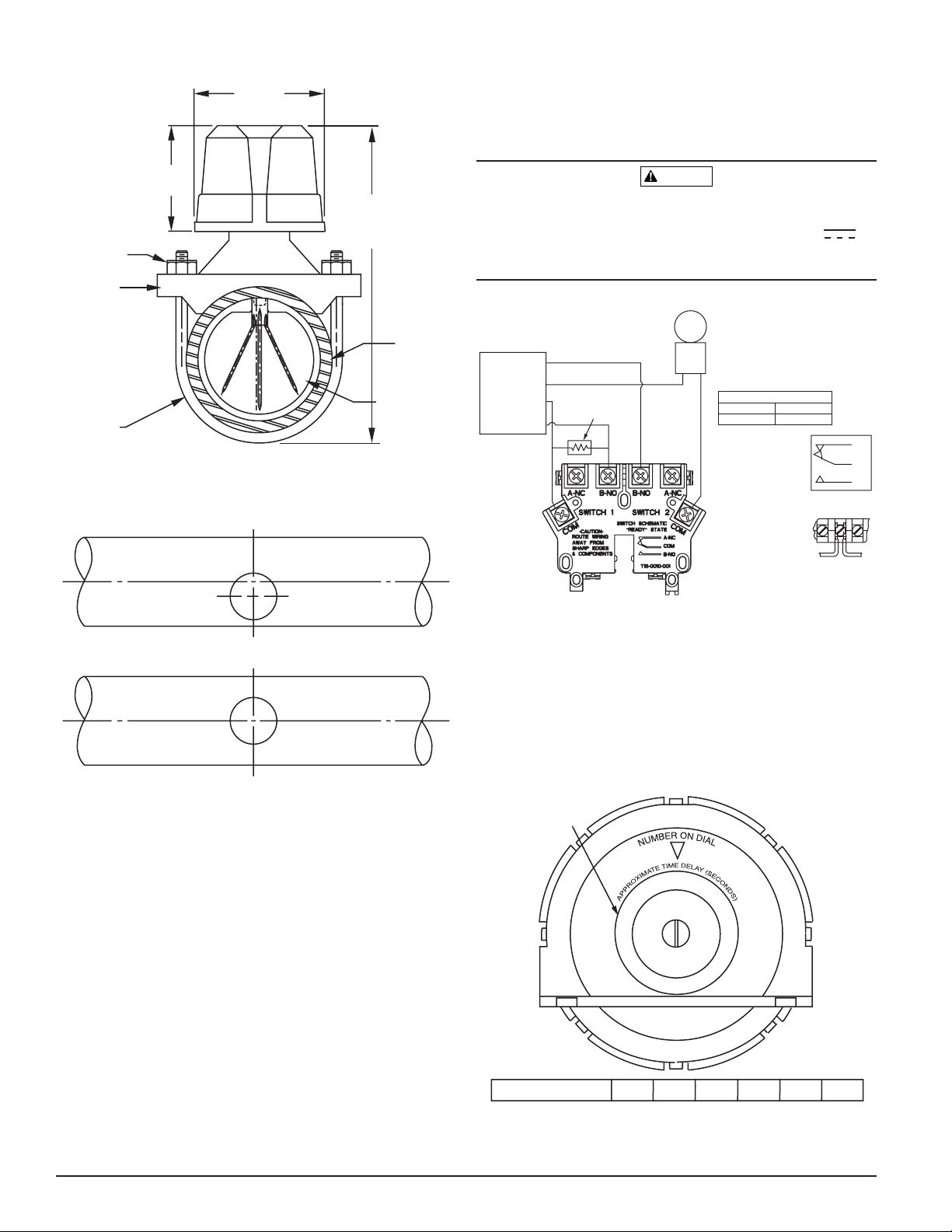
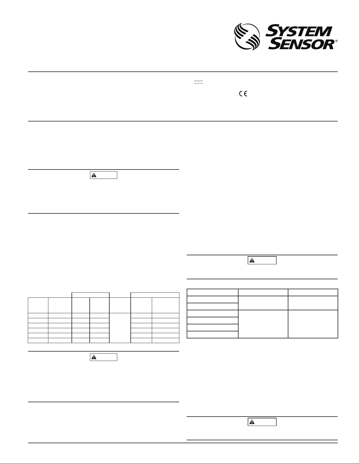
FIGURE 1. MOUNTING DIMENSIONS:
9.5 CM
OVERALL WIDTH = PIPE DIAMETER + 7.6 CM (3˝)
WRONG
AND FOREIGN MATTER FROM INSIDE WALL OF PIPE.
WARNING
(33/4˝)
7.6 CM
(3˝)
PIPE DIAMETER
PLUS 13.3 CM
1
/4˝)
U-BOLT
(5
NUT
PIPE
SADDLE
PIPE
PIPE
VANE
U-BOLT
W0105-00
FIGURE 2. LOCATION OF MOUNTING HOLE:
RIGHT
REMOVE BURRS FROM EDGE OF HOLE. CLEAN OUT SCALE
W0106-00
PREOPERATION TESTING
1. Fill the sprinkler system and check for leaks around the WFDE. If it
leaks, first check for proper torque on U-bolt nuts. If leak persists, drain
the system and remove the detector (see removal instructions under
Maintenance). Check for dirt or foreign objects under the gasket. Check
that pipe surface is not dented. Reinstall the detector and check again for
leaks. Do not proceed until all leaks have been stopped.
2. Connect an ohmmeter or continuity tester across (COM and B-NO) terminal switch contacts (see Figure 3). The ohmmeter should show an open
circuit, no continuity.
3. Deflect the actuator lever and hold it until the pneumatic delay shaft
releases the switch buttons. The ohmmeter or continuity tester should
show a short circuit after the delay has elapsed. If there is no delay,
check the setting of the delay adjustment dial.
FIELD WIRING
1. All models have two SPDT switches. Switch contacts (COM and B-NO) are
closed when water is flowing and open when water is not flowing. Connect the switches as shown in Figure 3 depending on the application.
2. When connected to a listed sprinkler/fire alarm control panel, the initiating circuit must be non-silenceable.
3. A ground screw is provided with all WFDE units. When grounding is required, clamp wire with screw in hole located between conduit entrance
holes, see Figure 6.
4. Use proper waterproof conduit fittings where required.
5. A 22.2 mm conduit hole is provided for electrical connection. An additional
22.2 mm diameter knockout is provided for multiple line connections.
High Voltage. Electrocution Hazard. Do not handle live AC wiring or work on a device to which AC power is applied. Doing so may result in severe injury or death.
When utilizing switches at voltages greater than 74VDC or
49VAC~means to provide all–pole disconnection must be incorporated in
the field wiring, such as a circuit breaker.
FIGURE 3. FIELD WIRING:
UL-LISTED
COMPATIBLE
CONTROL PANEL
LOOP
+
–
+
–
POWER
24VDC OR
120VAC
INITIATING
SSV120-X
SUGGESTED EOL
RESISTOR
SSM24-X
NOTE: COMMON AND B-NO
CONNECTIONS WILL CLOSE
WHEN VANE IS DEFLECTED, I.E.,
WHEN WATER IS FLOWING. DUAL
SWITCHES PERMIT
APPLICATIONS TO BE COMBINED
ON A SINGLE DETECTOR.
CONTACT RATINGS
125/250 VAC
24 VDC
SCHEMATIC OF
INDIVIDUAL
SWITCH IN
“NO WATERFLOW”
CONDITION
BREAK WIRE AS
SHOWN FOR
SUPERVISION OF
CONNECTION. DO
NOT ALLOW
STRIPPED WIRE
LEADS TO EXTEND
BEYOND SWITCH
HOUSING. DO NOT
LOOP WIRES.
10 AMPS
2.5 AMPS
A-NC
COM
B-NO
W0356-01
MECHANICAL DELAY ADJUSTMENT
The pneumatic delay is preset at dial setting 25 at the factory. To adjust the
delay, turn the adjustment dial on the delay mechanism. Turn clockwise to
increase the delay, counterclockwise to decrease the delay. Delay can be adjusted over a range from 0 to 30 seconds maximum, see Figure 4.
NOTE: Set the delay to the minimum required to prevent false alarms due to
flow surges.
After extended service, parts of the detector may become worn reducing the
delay time and causing false alarms. If this happens, increase the delay.
FIGURE 4. DELAY ADJUSTMENT DIAL:
DELAY
ADJUSTMENT
DIAL
0
5
10
25
20
15
DIAL SETTING
0
DIAL SETTING EQUALS DELAY IN SECONDS REFERENCE ONLY.
10 15 25
5
20
W0102-04
D770-53-00 2 I56-2617-004R
Page 3
OPERATIONAL TESTING
CAUTION
Always notify the central station monitoring waterflow alarms before repairing, maintaining or testing waterflow alarm devices.
1. Replace the cover and tighten the security screws with the security
wrench. Store the wrench in a secure place.
2. Open the inspector’s test valve and time how long it takes for the detector to indicate a flow condition. The detector should remain activated until the inspector’s test valve is closed. Air pockets in the sprinkler system
may increase the apparent time delay.
MAINTENANCE
To prevent accidental water damage, control valves should be shut tight and the
system completely drained before waterflow detectors are removed or replaced.
Inspect detectors monthly for leaks. If leaks are found, replace the detector.
Test detectors at least quarterly as described under Operational Testing above
to insure proper operation. Test more often as required by applicable codes
or standards.
Under normal conditions System Sensor waterflow detectors should provide
years of trouble-free service. If any part of the detector does not perform properly, replace the entire detector. Failure to follow this instruction may result in
failure of the detector to report a waterflow condition.
Proceed as follows to remove a detector:
1. Drain the pipe.
2. Turn off electrical power to the detector, and then disconnect wiring.
3. Loosen nuts and remove U bolts.
4. Gently lift the saddle far enough to get your fingers under it. With your
fingers, roll the vane so it will fit through the hole while continuing to lift
the waterflow detector saddle.
5. Lift detector clear of pipe.
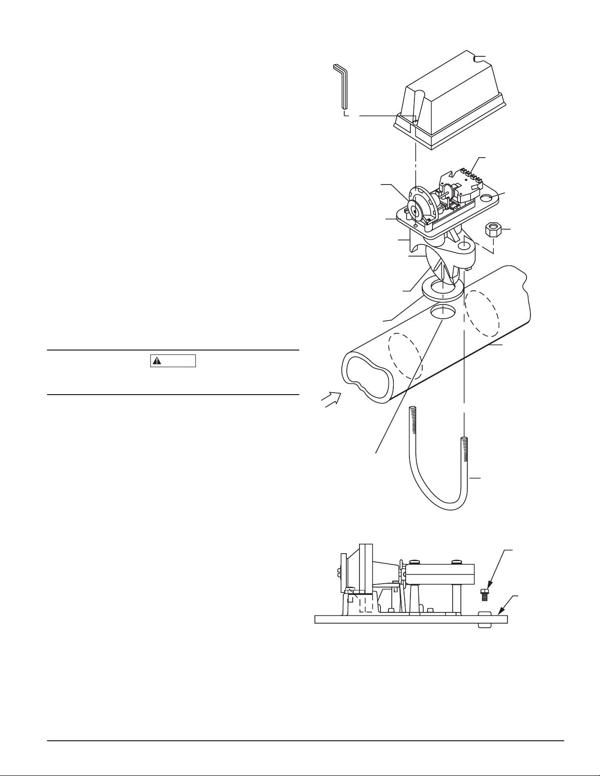
FIGURE 5. ASSEMBLY DIAGRAM:
COVER
TAMPER
PROOF
WRENCH
TERMINAL
BLOCK
DELAY
MECHANISM ELECTRICAL
CONDUIT
ENTRANCE
MOUNTING
PLATE
PIPE SADDLE
PLASTIC VANE
ROLL PADDLE
OPPOSITE OF
FLOW ARROW
WHILE INSERTING
SADDLE GASKET
PIPE
U-BOLT NUT
If a vane breaks off in a pipe, find and remove it. Failure to do so may
restrict the proper flow of water to part of the sprinkler system.
WATERFLOW
REFER TO
TABLE 2
U-BOLT
W0101 -02
FIGURE 6. GROUND SCREW LOCATION:
GROUND
SCREW
(GREEN)
MOUNTING
PLATE
W0103-00
D770-53-00 3 I56-2617-004R
Page 4
WARNING
Please refer to insert for the Limitations of Fire Alarm Systems
THE LIMITATIONS OF WATERFLOW ALARM DEVICES
1. Waterflow detectors may not work or operate properly if sprinkler piping being
monitored is plugged with pipe scale, mud, stones or other foreign material. Sprinkler
systems should be checked regularly for such blocking material.
2. Alarms generated by the activation of waterflow detectors may not be received by a
central station if telephone or other communication lines to the detector are out of
service, disabled, or open.
3. Vane-type waterflow detectors have a normal service life of 10–15 years. Hard water
systems, however, may reduce waterflow detector service life significantly.
THREE-YEAR LIMITED WARRANTY
System Sensor warrants its enclosed product to be free from defects in materials and
workmanship under normal use and service for a period of three years from date of
manufacture. System Sensor makes no other express warranty for this air duct smoke
detector. No agent, representative, dealer, or employee of the Company has the authority
to increase or alter the obligations or limitations of this Warranty. The Company’s obligation of this Warranty shall be limited to the replacement of any part of the product which
is found to be defective in materials or workmanship under normal use and service
during the three year period commencing with the date of manufacture. After phoning
System Sensor’s toll free number 800-SENSOR2 (736-7672) for a Return Authorization
number, send defective units postage prepaid to: System Sensor, Returns Department, RA
D770-53-00 4 I56-2617-004R
©2012 System Sensor
4. Waterflow detectors are not a substitute for insurance. Building owners should always
insure property and lives being protected by sprinkler systems.
5. If valves controlling the water supply to a sprinkler system are closed, vane-type waterflow detectors will not work. All valves controlling a sprinkler water supply should
be sealed or locked in the normally open position. The normally open position should
be monitored by a sprinkler supervisory switch.
#__________, 3825 Ohio Avenue, St. Charles, IL 60174. Please include a note describing
the malfunction and suspected cause of failure. The Company shall not be obligated to
replace units which are found to be defective because of damage, unreasonable use,
modifications, or alterations occurring after the date of manufacture. In no case shall the
Company be liable for any consequential or incidental damages for breach of this or any
other Warranty, expressed or implied whatsoever, even if the loss or damage is caused by
the Company’s negligence or fault. Some states do not allow the exclusion or limitation of
incidental or consequential damages, so the above limitation or exclusion may not apply
to you. This Warranty gives you specific legal rights, and you may also have other rights
which vary from state to state.
 Loading...