

Page 1

Voltage Drop
Calculator
User Guide – Version 2
Page 2

2
Voltage Drop Calculator
User Guide – Version 2
TABLE OF CONTENTS
1 DOWNLOAD AND INSTALLATION .........................3
1.1 Downloading ...........................................3
1.2 Installation..............................................4
2 USING THE CALCULATOR..................................5
2.1 New Project.............................................5
2.2 Open a Project..........................................6
2.3 Check for Updates .......................................8
3 DESIGN PAGE ............................................10
3.1 Create a Panel..........................................11
3.2 Create a Circuit.........................................14
3.3 Add Devices...........................................11
3.3.1 Add devices as step 3 ..............................11
3.3.2 Add devices using favorites.........................13
3.3.3 Add devices in the device listing Grid................14
4 FAVORITES MENU........................................22
5 SAVING AND E-MAILING .................................25
6 IMPORTING/EXPORTING PANELS OR CIRCUITS...........26
6.1 Import.................................................26
6.1.1 Importing Circuit ..................................25
6.1.2 Importing Panel ...................................27
6.2 Export.................................................27
6.2.1 Export Circuits .....................................27
6.2.2 Export Panel.......................................30
7 PRINTING ................................................31
7.1 Print Circuit............................................32
7.2 Print Panel .............................................34
7.3 Print All................................................35
8 ISSUES ENCOUNTERED IN VDC AND RESOLUTION .......36
Page 3
1 DOWNLOAD AND INSTALLATION
1.1 Downloading
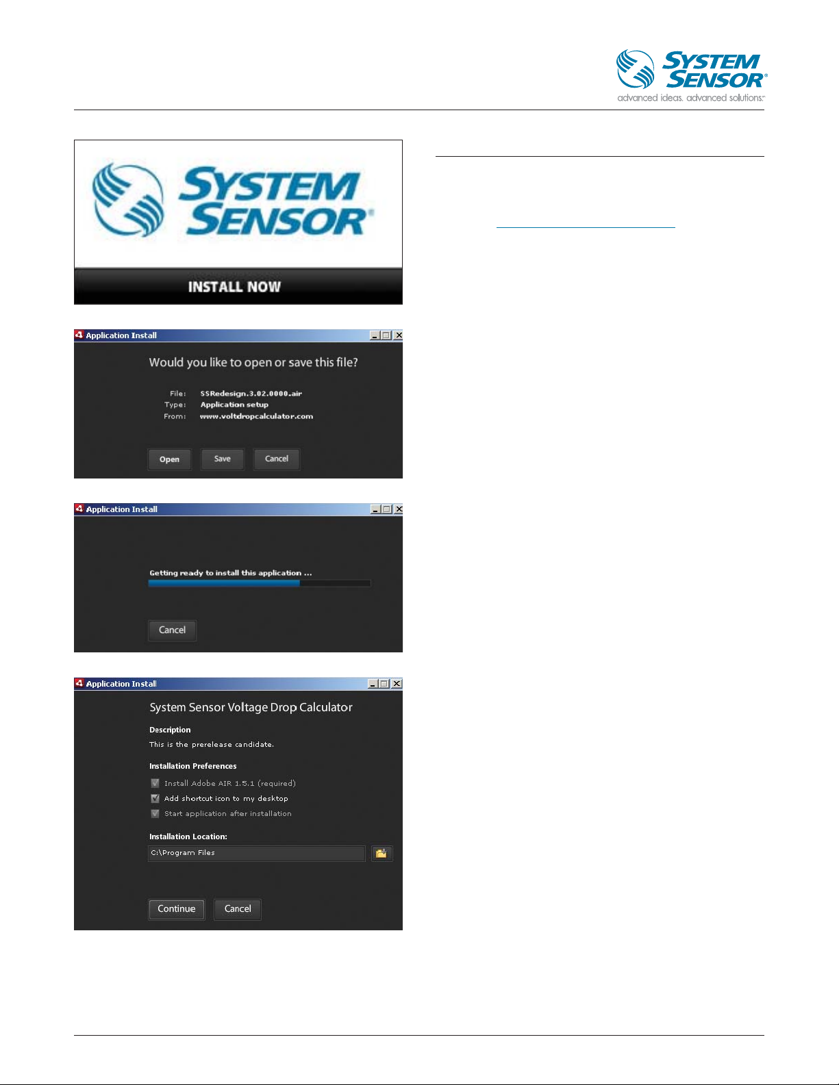
To download the Voltage Drop Calculator, point your Internet
browser to http://systemsensor.com/volt. After filling out
the required form you will be taken to the install page. Click
“Install Now” to open the Application Installer dialogue.
On the Application Install dialogue box, you can choose to:
Click “Open” to install now. Click “Save” to download and
save the file for later installation. Click “Cancel” to abort the
download process.
The application will begin to download after “Open” is
clicked. An action bar will track your progress through the
process. You can click “Cancel” at any time to abort the
download process.
You will be prompted to set your installation preferences.
Choose the default values or change them to fit your
requirements. Click “Continue”.
3
Voltage Drop Calculator
User Guide – Version 2
Page 4
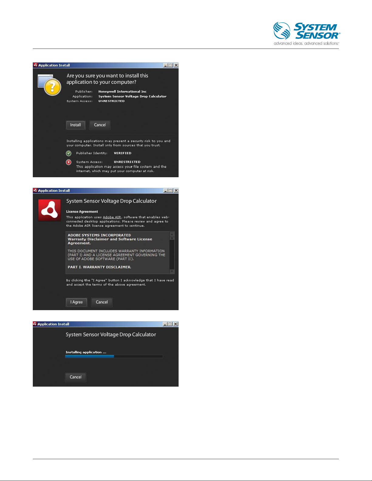
1.2 Installation
Next, the Application Install dialogue will ask you to verify
that you want to install the Voltage Drop Calculator on your
computer. Click “Install” to continue or “Cancel” to abort.
You will then be prompted to accept or decline the Voltage
Drop Calculator usage terms. Click “I Agree” to accept the
terms and continue the installation. Now, the Voltage Drop
Calculator will be installed on your computer.
The action bar will indicate progress. Once the installation is
complete, the Voltage Drop Calculator main page will open.
4
Voltage Drop Calculator
User Guide – Version 2
Page 5

2 USING THE CALCULATOR
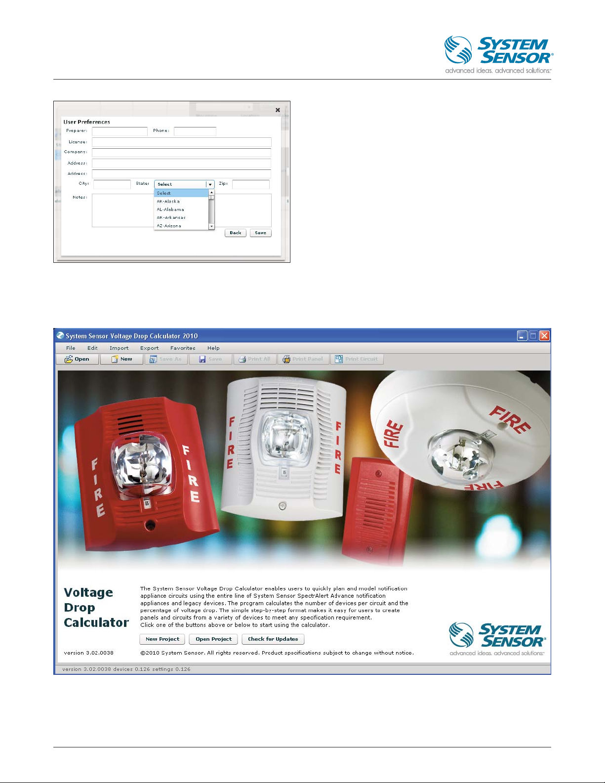
On the Voltage Drop Calculator main page, you can: Click “New Project” at the bottom or “New” on top to begin a new project,
Click “Open Project” at the bottom or “Open” on top to open a saved project. Click “Check for Updates” to download the latest
updates for the Voltage Drop Calculator. (NOTE: The Voltage Drop Calculator checks for new updates every time it is opened.)
2.1 New Project
When you open a new project by clicking “new project” at
bottom or “New” on top, you will be prompted to enter Job
Details. Enter your job details, for the state, select the details
from the combo box, though later in the application (for
printing device reports etc.) you will only see the state
abbreviation e.g. AK, AL etc. Click “Next” to continue.
NOTE: Job Details can be updated at any time via the “Edit”
tab in the upper left corner of the main Page. Click the
“Preferences” option.
5
Voltage Drop Calculator
User Guide – Version 2
Page 6
6
Voltage Drop Calculator
User Guide – Version 2
Next, you can set User Preferences. Enter your preferences
Here also Select the state from the combo box, though later
in the application you will only see the state abbreviation e.g.
AK, AL etc. (in printing reports options). Click “Save” to
continue or “Back” to return to Job Details.
NOTE: User Preferences can be updated at any time via the
“Edit” tab in the upper left corner of the Main Page. Click the
“Preferences” option.
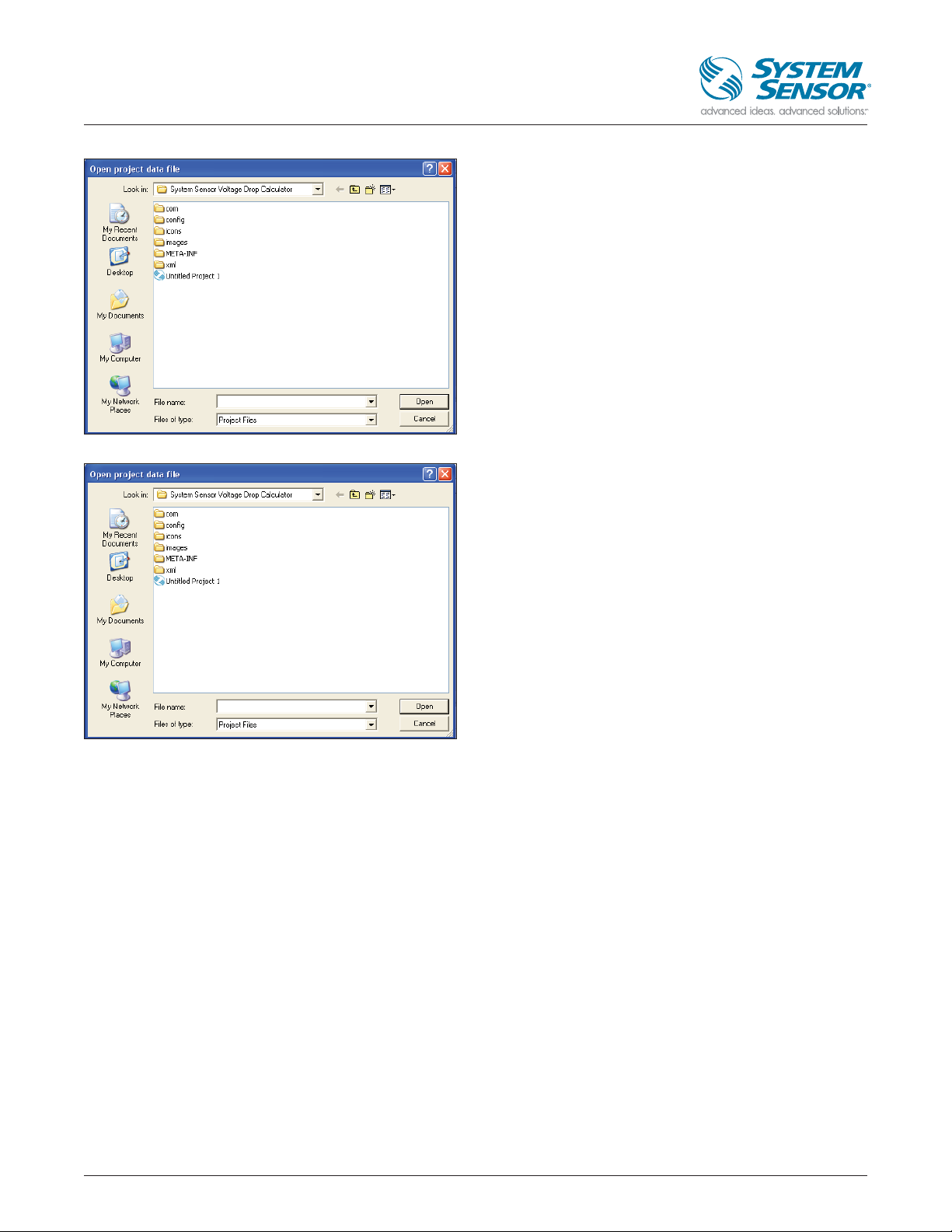
2.2 Open a Project
If a project has previously been already saved on the disk then it can be opened using the “Open project” button at the bottom
or the “Open” button at the top of the application.
Page 7
7
Voltage Drop Calculator
User Guide – Version 2
At the click of the button user will be shown the dialog box
to select the previously saved pjt file. Point to the location
where the file was saved and click on open button.
Now the application will open the selected project
named User_Guide.pjt and the application will be as shown
left with the details of panel, circuit and the devices saved in
the project.
Page 8

8
Voltage Drop Calculator
User Guide – Version 2
2.3 Check for Updates
At any time user can check if there are any updates with the devices details using “Check for updates” button at the bottom
or by clicking “Check for updates Under Help Menu” option.
Page 9

9
Voltage Drop Calculator
User Guide – Version 2
Once user clicks on Check for updates the application starts
pdating the details and user will see the corresponding screen.
And once the update is complete user will see the
corresponding screen
Page 10
10
Voltage Drop Calculator
User Guide – Version 2
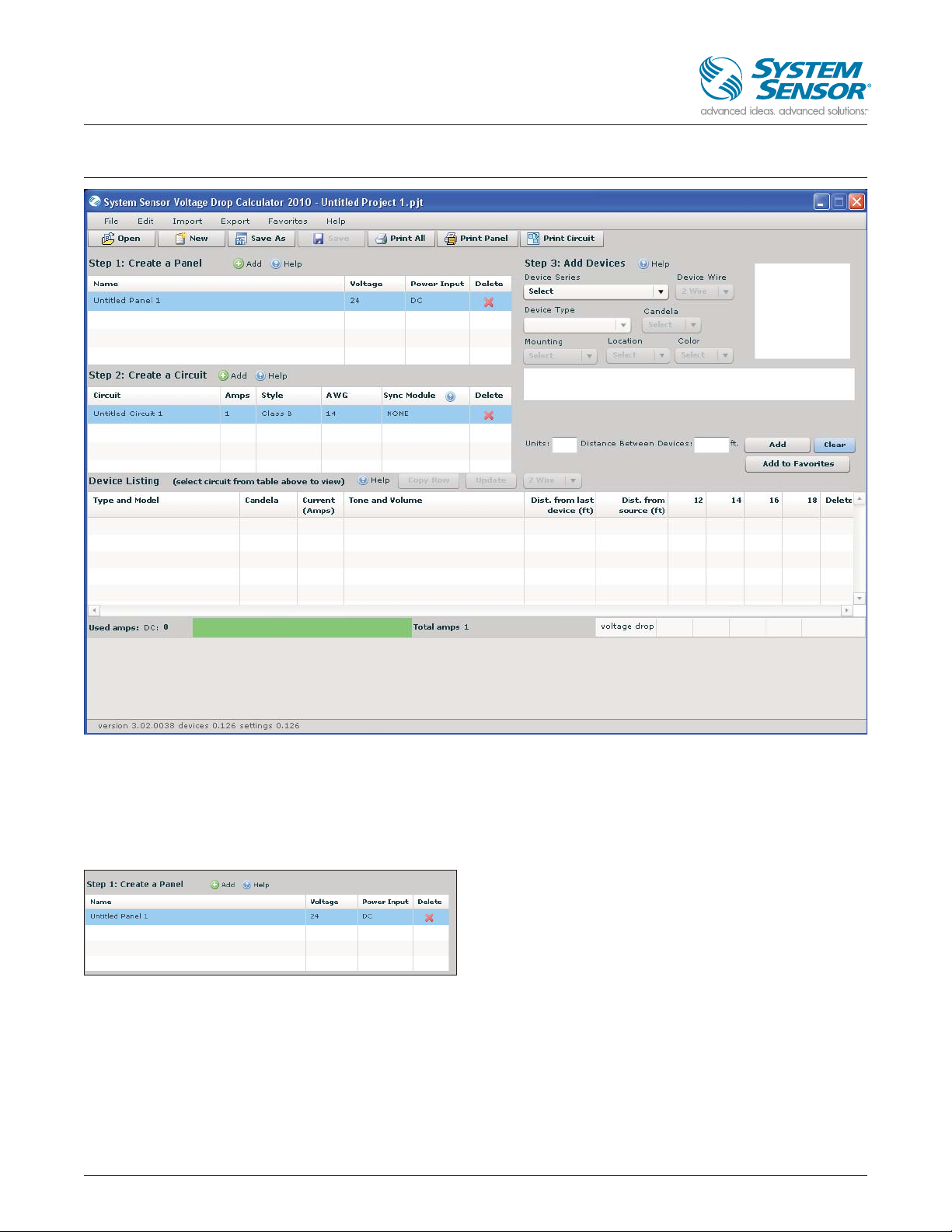
3 DESIGN PAGE
All project design work for the Voltage Drop Calculator is accessible from this page, including Create a Panel, Create a Circuit, and
device listing (adding devices). While these tasks can be completed in any order, this Help Guide performs the tasks in “step”
order.
NOTE: The default values for the Panel and Circuit can be updated to fit your specific job.
3.1 Create a Panel
When creating a panel, you can update the default values to
set the panel’s Name, Voltage, and Power Input. The panel’s
name can be changed by clicking on the default name (in
this case, “Untitled Panel 1”), and typing a new name.
Voltage and Power Input can be selected using drop-down
menus that appear by clicking on the current or default
value. To add another panel, click the green “Add” button. To
remove an existing panel, click the red “X” in the “Delete”
column. If more than one panel is in the design, select one at
a time to add circuits.
Page 11
11
Voltage Drop Calculator
User Guide – Version 2
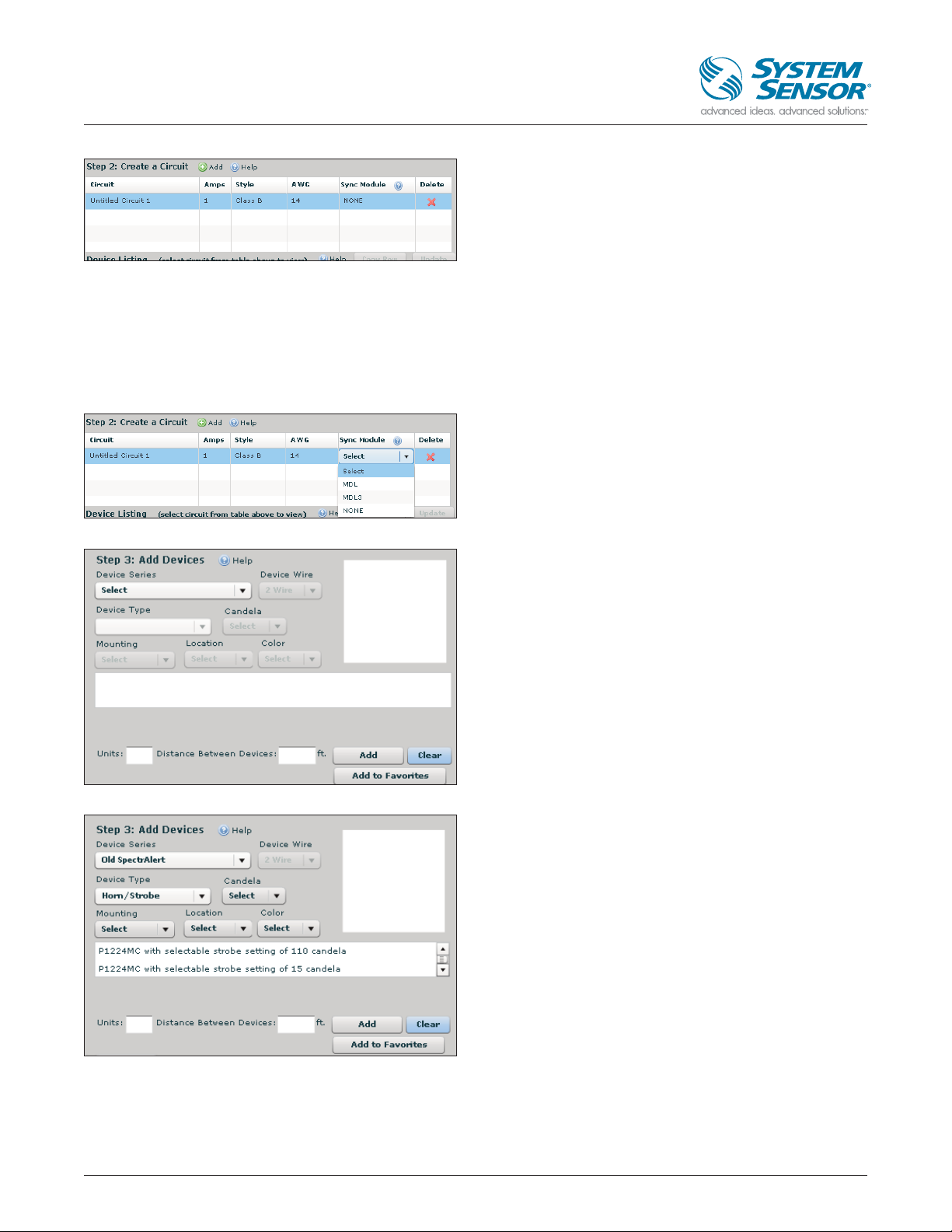
3.2 Create a Circuit
When creating a circuit, you can update the default values to
set the circuit’s Name, Amps, Style, AWG, and choose or
exclude a Sync Module. The circuit’s name can be changed
by clicking on the default name (in this case, “Untitled
Circuit 1”), and typing a new name. Amps value is changed
by clicking on the current or default value and entering your
criteria. Style, AWG, and Sync Module can be selected using
drop-down menus that appear by clicking on the current or
default value. To add another circuit, click the green “Add”
button. To remove an existing circuit, click the red “X” in the
“Delete” column.
Synchronization module options include System Sensor MDL
or MDL3 (new module released 4/1/09) devices. These
devices should be used if the System Sensor synchronization
protocol is not built into the panel or power supply. Choose
“NONE” if a sync module is not required for your application.
3.3 Add Devices
3.3.1 Add devices as step 3
Select device characteristics from the drop-down menus.
In the above screen shot, once user selects a Device series
type, the Device Type will list the different types of devices.
Based upon the device type selection, the other details will
be enabled or disabled based on the applicability.e.g.
In the above scenario for Horn/Strobe, there can be devices
of 2 wire type only in Oldlegacy SpectrAlert type and hence
2 wires is disabled (2 wire was the only option for the legacy
models).
Instead of selecting individual fields user can select the
device in the device details text box (The control in which
the details “In the screen shot the P1224MC with selectable
strobe of 110 candelas” have been displayed).
Also for some devices user must select Tone, volume
and /Or frequency to be able to add device in the circuit
as shown left.
Page 12

Above selection of P1224MC with selectable strobe setting
of 110 candelas uniquely selects a device and hence even if
we do not select Mounting, location or color, user will be
allowed to add devices to the circuit.
Once selections are made, at the click of Add button, devices are shown in the Device Listing section of the design page and
also graphically across the bottom device spacing line. Power usage is shown via the Used Amps bar graph (green shows power
remaining and red shows power used). Changes can be made within the Device Listing by clicking on the specific value you
want to change. In addition, dragging and dropping a device on the device spacing line will make changes throughout the
entire page.
12
Voltage Drop Calculator
User Guide – Version 2
Page 13

3.3.2 Add devices using favorites
After all the selections for a device to be added in the circuit
is done, you can optionally add the selected/configured
device as your favorite device based on the usage and need
of the device for quick reference and the device will be
added in the favorites menu list immediately.
Once you add a device as a Favorite device, it will be listed
under favorites in one of the following format based on the
device type
1) Label Model : If no tone, volume, frequency and candela is
applicable e.g.
Chime CH1224W
2) Label Model, Tone Volume : If no frequency and candela is
applicable
Chime CHR, 1 Second chime, High
3) Label Model, Tone Volume Frequency : If no candela is
applicable
Horn H12/24, Temporal, High, Electromechanical
4) Label Model, Tone Volume Frequency , candela: If all are
applicable
Horn/Strobe P2R Temporal, High, 110 candela
If a specific device with selected configuration already
exists in the favorite’s list then user will be intimated about
it as shown
13
Voltage Drop Calculator
User Guide – Version 2
Page 14

3.3.3 Add devices in the device listing Grid
Alternately, to add devices you do not need to return to step 3 every time. The devices can be added in the Device Listing
section of the design page grid also as explained below.
User can simply select a row and click on the copy row button. Once user clicks on the “copy row” button, a new row with the
same details of the row being copied is listed but without any calculations.
14
Voltage Drop Calculator
User Guide – Version 2
Page 15

For a device already existing in the device listing section of application (e.g. when an already saved project is opened), the
changes will not be allowed initially but if user clicks Type and Model column in the grid and changes the type and model for a
specific row only then candela, tone, volume or frequency can be changed based on device type applicability.
Note:
1) It is strongly advised to update the “Type and Model” and then update details for the device such as candela
and tone volume and/or frequency.
2) If user changes the Distance from last device (ft), then the calculations will be done automatically without clicking
update button.
15
Voltage Drop Calculator
User Guide – Version 2
Page 16

For a Horn/Strobe tone of type PC2475W the candela is applicable hence the candela column will be as shown below.
16
Voltage Drop Calculator
User Guide – Version 2
Page 17

For a Horn/Strobe tone of type PC2475W the Tone and volume are applicable and hence they can be modified as shown below.
17
Voltage Drop Calculator
User Guide – Version 2
Page 18

18
Voltage Drop Calculator
User Guide – Version 2
After all the changes are done for a device configuration click the update button on top. All of the calculations to be updated
and the row which was copied without calculations now will be updated with the voltage drop calculations. Once user clicks on
update button the device listing grid again is disabled and if any changes are made, user again needs to select the Type and
Model column.
Note: If user clicks on copy row and there is any previous
row which has not been updated the user will be given
a message to update the previously unsaved rows as
shown left.
Page 19

19
Voltage Drop Calculator
User Guide – Version 2
Consider a scenario where the user is supposed to select
candela for the device or Tone and Volume and they don’t
select it, in that case user will see the corresponding message.
Also in a circuit user can not combine 2-wire devices and
4-wire devices, hence when user tries to change the wire
type either in step 3 to add devices or in the grid section
using Wire Type combo box, user will be given a message
as seen left.
If user clicks on OK button, the grid will be cleared of all the 2-wires devices.
Page 20

20
Voltage Drop Calculator
User Guide – Version 2
Now in the step 3 to Add devices 4 wire devices will be available as shown below.
And if user clicks cancel when the option to change the circuit
wire type is given as shown left.
Page 21

21
Voltage Drop Calculator
User Guide – Version 2
In this scenario the circuit will remain as it is with the wire type being the previous type.
Page 22

22
Voltage Drop Calculator
User Guide – Version 2
4 FAVORITES MENU
Initially if a project is not opened then Favorite devices will be disabled. Once a new project or an already existing project is
opened the selected favorite devices will be enabled under favorite menu option.
Note:
1. Even if user closes the application, the favorites will be listed under favorite menu, next time the application is opened.
2. At a time there can be 15 favorite devices and if user adds favorites more than 15 then automatically the device which was
added first will be removed first and the recent device will be added in the list of favorites.
Once user selects a device in the favorites menu, user is
prompted to give details of number of units and distance
between the devices in the corresponding pop up form.
Based on number of units and distance between devices, the
devices with specified configuration are added in the circuit.
Page 23

23
Voltage Drop Calculator
User Guide – Version 2
Consider a scenario where the user is supposed to select candela for the device or Tone and Volume and they don’t select it, in
that case user will see the message left when they select a device in Favorites.
As shown below there is a row which is not updated in the below grid and user is selecting a device from Favorites.
Page 24

24
Voltage Drop Calculator
User Guide – Version 2
When user clicks on the device, they will see the
corresponding message.
As shown in the screen shot the CHR does not have Tone
and Volume selected hence when user clicks on Update
button, they will see the message shown left.
Now if user goes and fills details for Tone and Volume and
click on update button, user can continue adding devices
from favorites.
If currently a circuit has all the 4-wire devices and user tries to
add a 2-wire device from the favorites, then user will be
given a message as shown left and the device will not be
added, but any 4-wire device can be added.
Similarly if the circuit contains 2-wire devices then 4-wire
devices from favorites can not be added.
Page 25

25
Voltage Drop Calculator
User Guide – Version 2
5 SAVING AND E-MAILING
To save your project, click on Save as button on top or
choose “File” in the upper left corner and click on “Save As”.
Name the file and save it onto your computer. This file
can now be shared with anyone in your network or can
be e-mailed to the design team. To open a saved project,
choose “File” in the upper left corner and click on “Open”.
You can then navigate to the file’s saved location on your
computer and open the file. You can also open saved
projects directly from your computer’s file system. However,
the VDC application must be on the computer in order to
open the file.
Once a file is saved to your computer, it can be sent via
e-mail to everyone on the project team that needs to review
the design or installation. However, the VDC application must
be on the destination computer to open the file. See the
Download section for step-by-step instructions.
Page 26

26
Voltage Drop Calculator
User Guide – Version 2
6 IMPORTING/EXPORTING PANELS OR
CIRCUITS
Select “Import” from the top menu bar to import panels
or circuits.
6.1 Import
6.1.1 Importing Circuit
Select “Circuit” from the drop-down menu to import a circuit.
Selecting “Circuit” opens a dialogue to choose which panel
the import will be used in. Click on the panel you want to
use. Then click “OK” to continue or “Cancel” to abort.
A window showing your computer files will open next.
Navigate to the circuit you want to import, select it, and
click “Open”.
Page 27

27
Voltage Drop Calculator
User Guide – Version 2
6.1.2 Importing Panel
Select “Panel” from the drop-down menu to import a panel.
A window showing your computer files will open next.
Navigate to the panel you want to import, select it, and
click “Open”.
6.2 Export
6.2.1 Export Circuits
To export panels or circuits, select “Export” from the top
menu bar.
To export a circuit, select “Circuit” from the drop-down menu.
Page 28

28
Voltage Drop Calculator
User Guide – Version 2
Selecting “Circuit” opens a dialogue to choose which panel
the export will be taken from. Click on the panel you want to
export the circuit from.
Page 29

29
Voltage Drop Calculator
User Guide – Version 2
Then click on the circuit that you want to export. At any time,
you can click on “Cancel” to abort.
A window showing your computer files will open next.
This allows you to export and save the circuit file to your
computer. Name the file and save it to your computer
network. This file can now be accessed and shared with
anyone in your network or can be e-mailed to the design
team. Opening your saved file is done just like opening
any other files.
Page 30

30
Voltage Drop Calculator
User Guide – Version 2
6.2.2 Export Panel
Click on the panel that you want to export.
Click on the panel that you want to export.
At any time, you can click “Cancel” to abort. A window
showing your computer files will open next. This allows you
to export and save the panel file to your computer. Name the
file and save it to your computer network. This file can now
be accessed and shared with anyone in your network or can
be e-mailed to the design team. Opening your saved file is
done just like opening any other files.
Page 31

31
Voltage Drop Calculator
User Guide – Version 2
7 PRINTING
The printing feature accommodates multiple types of submission forms.
1) Click on “Print all” button if you want to print all the content
2) Click on “Print panel” if you want to print all the details of a specific Panel
3) Click on “Print Circuit” if you want to Print all the details of a specific circuit.
Alternately click on or choose “File” in the upper left corner
and choose “Print”. Three options appear: “Print Circuit”,
“Print Panel”, and “Print All”.
Page 32

32
Voltage Drop Calculator
User Guide – Version 2
7.1 Print Circuit
Selecting “Print Circuit” button on top of application or
under “File->Print->Print circuit menu “ option opens a
window to choose which panel should be printed. Click on
the panel you want to print.
Page 33

33
Voltage Drop Calculator
User Guide – Version 2
The window will expand so that you can select the circuit.
Click on the circuit you want to print.
Click “OK” to continue or “Cancel” to abort.
A window with a sample of the form will open next. If this is
the submission form format needed, click the “Print” tab.
This will direct you to your printer settings.
Page 34

34
Voltage Drop Calculator
User Guide – Version 2
7.2 Print Panel
Selecting “Print Panel” button on top of the application or
“File-> Print->Print Circuit menu“ option opens a dialogue
to choose which panel should be printed. Click on the panel
you want to print. Click “OK” to continue or “Cancel” to abort.
A window with a sample of the form will open next. If this is
the submission form format needed, click the “Print” tab. This
will direct you to your printer settings.
Page 35

35
Voltage Drop Calculator
User Guide – Version 2
7.3 Print All
Selecting “Print All” button at the top of the application or
“File->Print->Print All menu” option opens a window with
a sample of the form. Multiple pages will appear based upon
the number of devices that are contained in the circuit. A
separate page will be generated for each panel and
corresponding circuits.
If this is the submission form format needed, click the “Print”
tab. This will direct you to your printer settings.
Page 36

36
Voltage Drop Calculator
User Guide – Version 2
8 ISSUES ENCOUNTERED IN VDC AND
RESOLUTION
1) Sometimes when VDC is opened it will be blank and no
panel and circuit will be created.
Resolution: If a user encounters such a problem please go
to C:\Documents and settings\<EID folder> e.g.
C:\Documents and Settings\E343810\Application
Data and delete any folder with voltage drop calculator
name, it can have different folders with a unique ID
appended to it, delete all those folders also if there is any
other folder with the name SSRedesign delete that folder
also as shown left.
Restart VDC tool and the application will execute properly.
System Sensor
3825 Ohio Avenue
St. Charles, IL 60174
www.systemsensor.com
info@systemsensor.com
800/736-7672 toll-free
630/377-6580 main
630/377-7871 fax
 Loading...