

Page 1
INSTALLATION AND MAINTENANCE INSTRUCTIONS
V4R24ADA Series Speaker/Strobes
for Fire Protective Signaling Systems
Specifications
Speaker
Frequency Range: 400 Hz to 4000Hz
Supervision: Capacitive input for supervisory DC voltage
Mounting: Standard 4" X 4" electrical box
Surface mount directly to box
Semiflush mount, using model MP-SF or MP-SFB
Input
Voltage
(Vrms)
25 or 70.7 1/4 75 78
25 or 70.7 1/2 78 81
25 or 70.7 1 81 84
25 or 70.7 2 84 87
Strobe
Power
Tap
(Watts)
Minimum Output (dBA)
UL
Reverberant
Anechoic
@ 10 ft.
A Division of Pittway
3825 Ohio Avenue, St. Charles, Illinois 60174
1-800-SENSOR2, FAX: 630-377-6495
Model Supply
V4R24110ADA
V4R2475ADA
V4R2415ADA
V4R241575ADA
Operating Current from
Voltage
Range
Regulated Supply
Average
Operating
Current
Peak
Current
(mA)
20/30V
Inrush
Current
(mA in
access
of Peak)
20-30V 210 470/500 0 245 400/500 0.08
20-30V 170 385/400 0 200 320/370 0.04
20-30V 75 160/180 0 90 275/290 0.02
20-30V 93 210/220 0 120 275/290 1.0
Operating Current from Full-Wave
Rectified Unfiltered Supply
Average
Operating
Current
(mArms)
Peak
Current
(mA)
20Vrms/
30Vrms
NOTE: Inrush current duration is less than 20 microseconds (.00002 seconds).
General
The National Fire Protection Association has published
standards and recommended practices for the installation
The speaker is also equipped with a capacitive input to al-
low for DC supervision.
and use of the appliances described in these instructions. It
is recommended that the installer become familiar with
these standards and practices, local codes, and any special
requirements of the authority having jurisdiction.
An attached 24 VDC strobe at 110, 75, 15, or 15/75 candela
(cd) is also included with the speaker. Although they are
assembled into a unit, the strobe and speaker are electri-
cally independent and require separate power sources.
The speakers can operate at any one of four input power
levels at either of two input voltages. The system voltage
and sound power levels are selected at the time of installa-
Strobes can be powered by means of a full-wave rectified
unfiltered supply.
tion, but can be changed, if necessary.
Inrush
Current
(Amps in
excess
of Peak)
D900-02-00 1 I56-655-03
Page 2
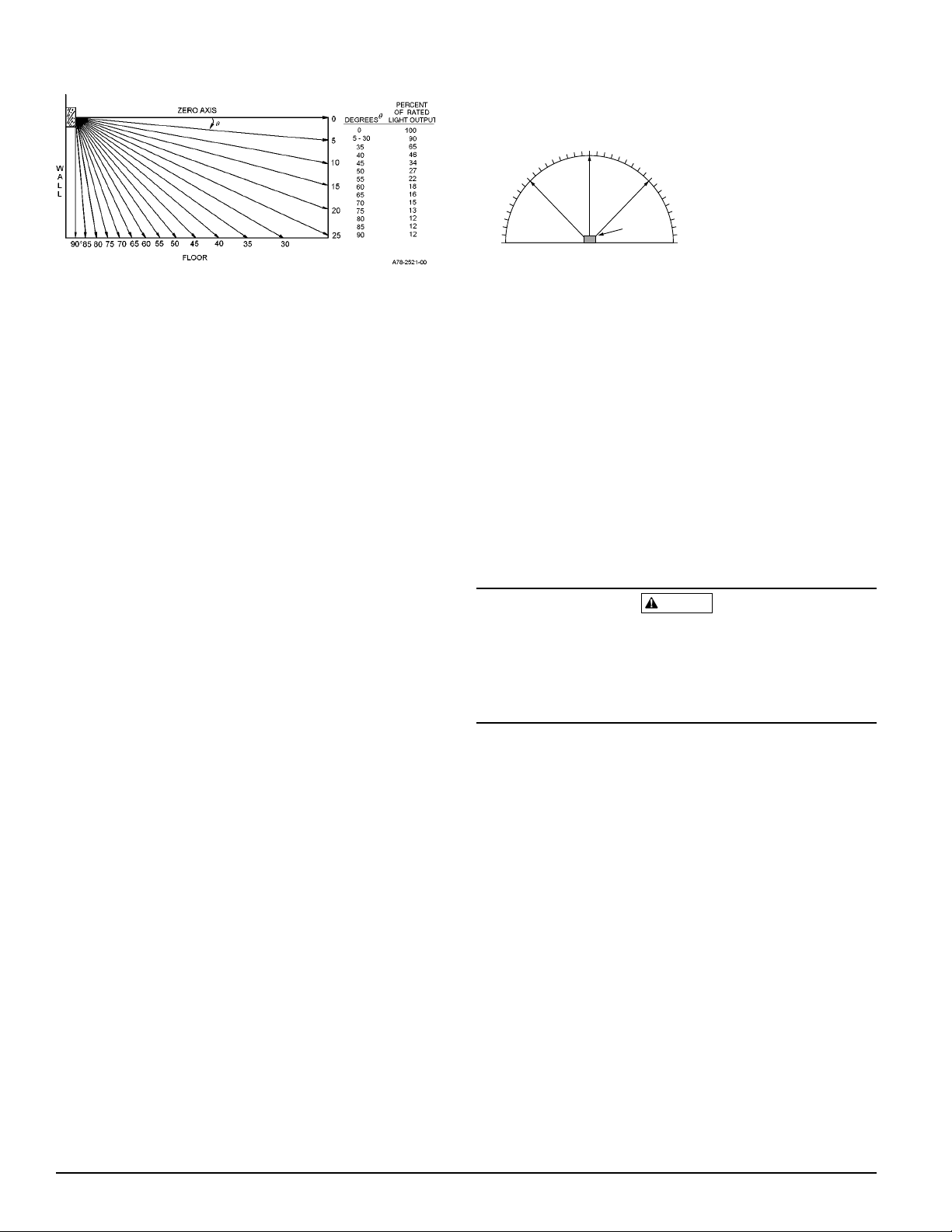
Figure 1. Vertical and horizontal light distribution:
0˚
45˚
90˚ –90˚
–45˚
LIGHT
Degrees % of Rating
0100
5 - 25 90
30 - 45 75
50 55
55 45
60 40
65 35
70 35
75 30
80 30
85 25
90 25
The light output rating of the Model V4R24110ADA is 110
cd; the V4R2475ADA is 75 cd; the V4R2415ADA is 15 cd.
The light output rating of the Model V4R241575ADA is 15
cd (See Figure 1).
NOTE: The light output at 0° viewing angle for
V4R241575ADA is 75 cd (See Figure 1).
Installation - For Strobe Placement See NFPA 72,
Chapter 6
NOTE: Installation procedure must comply with all appli-
cable local codes and any special requirements of
the authority having jurisdiction.
Electrical
All wiring must be installed in compliance with the National Electrical Code and all applicable local codes as well
as any special requirements of the authority having jurisdiction, using the proper wire size. This also includes all
applicable NFPA Standards, ANSI/UL 1480, and NEC 760.
1. Connect the speaker and strobe as shown in Figure 2.
Keep in mind that even though the speaker and strobe
are a single mechanical unit, they are electrically independent - the strobe must be connected to a DC supply
and the speaker to a 25V
or 70.7 V
rms
amplifier.
rms
2. See Figure 2. The speaker is equipped with five posts
and an associated plug with red and black wires. The
center post is COM (common) while the others are labeled 2W, 1/4W, 1/2W, and 1W, respectively.
The installer selects any one of four input power levels
by installing the plug onto COM and the appropriate
power post. When connecting this plug, make sure the
black wire is connected to the COM post and the red
wire to the numbered post. Otherwise, permanent
speaker damage could result.
CAUTION
If the power option plug is not plugged into one of the option positions, the speaker will not sound and there will be
no trouble indication at the panel. Always make sure that
the individual speakers are tested after installation per
NFPA regulations.
Mounting
A. General
Both slotted head and Phillips head screws are supplied
with the speaker/strobe. Use the slotted head screw to
mount the device or combination of devices on the electrical box. Use the phillips head screws for attaching accessories to the speaker.
Even though V4R24ADA series speakers can be used
with 25 V
or 70.7 V
rms
amplifiers, permanent damage
rms
The speaker/strobe must be wall mounted so that the
top of the lens is 24 inches below the ceiling.
can result if the speaker is improperly connected. Therefore, be sure to use the COM and 25 terminals when a 25
V
amplifier is being used. Similarly, use the COM and
rms
70.7 terminals if a 70.7 V
amplifier is in the system.
rms
B. Surface Wall Mount
See Figure 3. Attach the speaker/strobe to a standard 4inch electrical box, using the two 8-32 X 1-7/16" slotted
screws provided. Fill the remaining screws with the
NOTE: Do NOT loop electrical wiring under terminal
short #8 sheet metal screws, provided.
screws. Wires connecting the device to the control
panel must be broken at the device terminal connection to ensure electrical supervision.
D900-02-00 2 I56-655-03
Page 3

Figure 2:
FROM
PANEL OR
PREVIOUS
DEVICE
STROBE
25 OR
70.7V
2W
1W
COM 25 70.7
1/4W
1/2W
TO
NEXT
DEVICE
OR
EOL
TO
NEXT
DEVICE
OR
EOL
A78-1792-01
C. Semiflush Wall Mount
(a) System Sensor semiflush mounting plates are
shipped with #8 nuts already installed from the
back.
(b) Attach the semiflush mounting plate to a standard 4-
inch square electrical box using the two 8-32 X 5/8"
slotted screws, provided, at diagonally opposite corners, as shown in Figure 4.
(c) Wire the speaker/strobe as described in Electrical and
mount it on the plate using the two 8-32 X 1-7/16"
slotted screws in diagonally opposite corners. Thread
a #8 sheet metal screw into each of the two remaining
holes in the speaker/strobe.
D. Plaster Ring Mount
See Figure 5. Follow the Semiflush Wall Mount procedure, except attach the semiflush plate to the electrical
box, using the two 6-32 X 5/8" screws.
Figure 3. Surface wall mount:
V400
#8 Sht. Mtl.
Figure 5. Plaster ring mount:
Signal Strobe
8-32x1-7/16
8-32x1-7/16
#8 Sht. Mtl.
6-32x5/8
A78-1794-02
Figure 4. Semiflush wall mount:
MP-SF
8-32x5/8
8-32x5/8
V400
#8 Sht. Mtl.
#8 Sht. Mtl.
V400
Signal Strobe
#8 Sht. Mtl.
8-32x1-7/16
8-32x1-7/16
A78-1796-02
Signal Strobe
8-32x1-7/16
8-32x5/8
6-32x5/8
8-32x1-7/16
#8 Sht. Mtl.
A78-1799-01
D900-02-00 3 I56-655-03
Page 4

The Limitations of Speakers and Speaker/Strobes
If the power option plug is not plugged into one of the option positions,
the speaker will not sound and there will be no trouble indication at the
panel. Always make sure that the individual speakers are tested after installation per NFPA regulations.
The speaker may not be heard. The loudness of the speaker meets (or
exceeds) the current Underwriters Laboratories standards. However, the
speaker may not attract the attention of a sound sleeper or one who has
recently used drugs or has been drinking alcoholic beverages. The speaker
may not be heard if it is placed on a different floor from the person in hazard or if placed too far away to be heard over the ambient noise, such as
traffic, air conditioners, machinery, or music appliances that may prevent
alert persons from hearing the alarm. The speaker may not be heard by
persons who are hearing impaired.
WARNING
and must be installed within an area where it can be seen by building occupants. The strobe must not be installed in direct sunlight or areas of
high light intensity (over 60 foot candles) where the visual flash might be
disregarded or not seen. The strobe may not be seen by the visually im-
paired.
The signal strobe may cause seizures. Individuals who have positive
photic response to visual stimuli with seizures, such as persons with epilepsy, should avoid prolonged exposure to environments in which strobe
signals, including this strobe, are activated.
The signal strobe cannot operate from coded power supplies. Coded
power supplies produce interrupted power. The strobe must have an uninterrupted source of DC power in order to operate correctly.
The signal strobe may not be seen. The electronic visual warning signal
uses an extremely reliable xenon flash tube. It flashes at least once every
second and meets the 1971 Underwriters Laboratories standard for the
System Sensor recommends that the speaker and signal strobe always be
used in combination so that the risks from any of the above limitations are
minimized.
hearing impaired. The visual warning signal is suitable for direct viewing
Three-Year Limited Warranty
System Sensor warrants its enclosed speaker/strobe to be free from defects
in materials and workmanship under normal use and service for a period
of three years from date of manufacture. System Sensor makes no other
express warranty for this speaker/strobe. No agent, representative, dealer,
or employee of the Company has the authority to increase or alter the obligations or limitations of this Warranty. The Company’s obligation of this
Warranty shall be limited to the repair or replacement of any part of the
speaker/strobe which is found to be defective in materials or workmanship under normal use and service during the three year period commencing with the date of manufacture. After phoning System Sensor’s toll free
number 800-SENSOR2 (736-7672) for a Return Authorization number,
send defective units postage prepaid to: System Sensor, Repair Depart-
ment, RA #__________, 3825 Ohio Avenue, St. Charles, IL 60174. Please
include a note describing the malfunction and suspected cause of failure.
The Company shall not be obligated to repair or replace units which are
found to be defective because of damage, unreasonable use, modifications, or alterations occurring after the date of manufacture. In no case
shall the Company be liable for any consequential or incidental damages
for breach of this or any other Warranty, expressed or implied whatsoever,
even if the loss or damage is caused by the Company’s negligence or fault.
Some states do not allow the exclusion or limitation of incidental or consequential damages, so the above limitation or exclusion may not apply to
you. This Warranty gives you specific legal rights, and you may also have
other rights which vary from state to state.
D900-02-00 4 I56-655-03
© System Sensor 1996
 Loading...