

Page 1

INSTALLATION AND MAINTENANCE INSTRUCTIONS
V400R(Red), V400B(Beige), and
V400W(White) Speakers for Fire Protective
Signaling Systems
V400R and V400B also for use with these listed strobes:
SS12LO, SS24LO, SS24LOC, SS24M, and SS24MC
Specifications
Voltage Input: 25 V
Input Power Taps:
Frequency Range: 400 to 4000 Hz
Supervision: Capacitive input for supervisory DC voltage
Grille Size: 4" X 4"
Cone Material: Weather resistant
Mounting: Standard 4" X 4" electrical box
Input Terminals: 14 to 18 AWG
Operating Temperature Range: 32° to 120°F
General Description
The National Fire Protection Association has published
standards and recommended practices for the installation
and use of the appliances described in these instructions.
System Sensor recommends that the installer become familiar with these standards and practices, local codes, and
any special requirements of the authority having jurisdiction.
The speaker can operate at any one of four input power levels (1/4, 1/2, 1, or 2 watts) at either of two input voltages
(25V
or 70.7V
rms
). The rms voltage and power levels are
rms
selected at the time of installation, but can be changed, if
necessary.
The speaker is equipped with a capacitive input to allow
for DC supervision.
Optional strobes are available for use with the speaker. Although they are assembled into a unit at the time of installation, the strobe and speaker are electrically independent
and require separate power sources. Strobes must be powered by means of an uncoded full-wave rectified, filtered or
unfiltered supply. Model SS12LO is for use with 12 volt
panels and Models SS24LO and SS24M are for 24 volt panels. The strobe CANNOT be supervised when it is attached
to the speaker and is considered a supplementary signaling
device.
or 70.7 V
rms
1
/4 Watt, 1/2 Watt, 1 Watt, or 2 Watts
rms
Surface mount directly to box
Semiflush mount, using model MP-SF, MP-SFB, or MP-SFW
Flush mount, using Model MP-F, MP-FB, or MP-FW
Ceiling mount, using flush mount kit MP-F or MP-FB; use Models SS24LOC and
SS24MC Strobes (optional) for ceiling-mounted installations.
Installation
Electrical
Install the electrical wiring in compliance with all applicable local codes as well as any special requirements of the
authority having jurisdiction, using the proper wire size.
1. Connect the speaker and strobe as shown in Figure 1.
Keep in mind that if an optional strobe has been attached to the speaker, the speaker and strobe are electrically independent. The speaker must be connected to a
25V
or 70.7V
rms
DC power supply.
Even though V400 series speakers can be used with
25V
or 70.7V
rms
sult if the speaker is improperly connected. Therefore,
be sure to use the COM and 25 terminals when a 25V
amplifier is being used. Similarly, use the COM and 70
terminals if a 70.7V
NOTE: Do NOT loop electrical wiring under terminal
screws. Wires connecting the device to the control
panel must be broken at the device terminal connection to ensure electrical supervision.
2. See Figure 1. The speaker is equipped with five posts
and an associated plug with red and black wires. The
center post is labeled COM (common) while the others
are labeled 2W, 1/4W, 1/ 2 W, and 1W, respectively.
These posts enable the installer to select any one of four
power levels by installing the plug onto COM and the
A Division of Pittway
3825 Ohio Avenue, St. Charles, Illinois 60174
1-800-SENSOR2, FAX: 630-377-6495
amplifier and the strobe to an uncoded
rms
amplifiers, permanent damage can re-
rms
amplifier is in the system.
rms
rms
D900-03-00 1 I56-380-05
Page 2
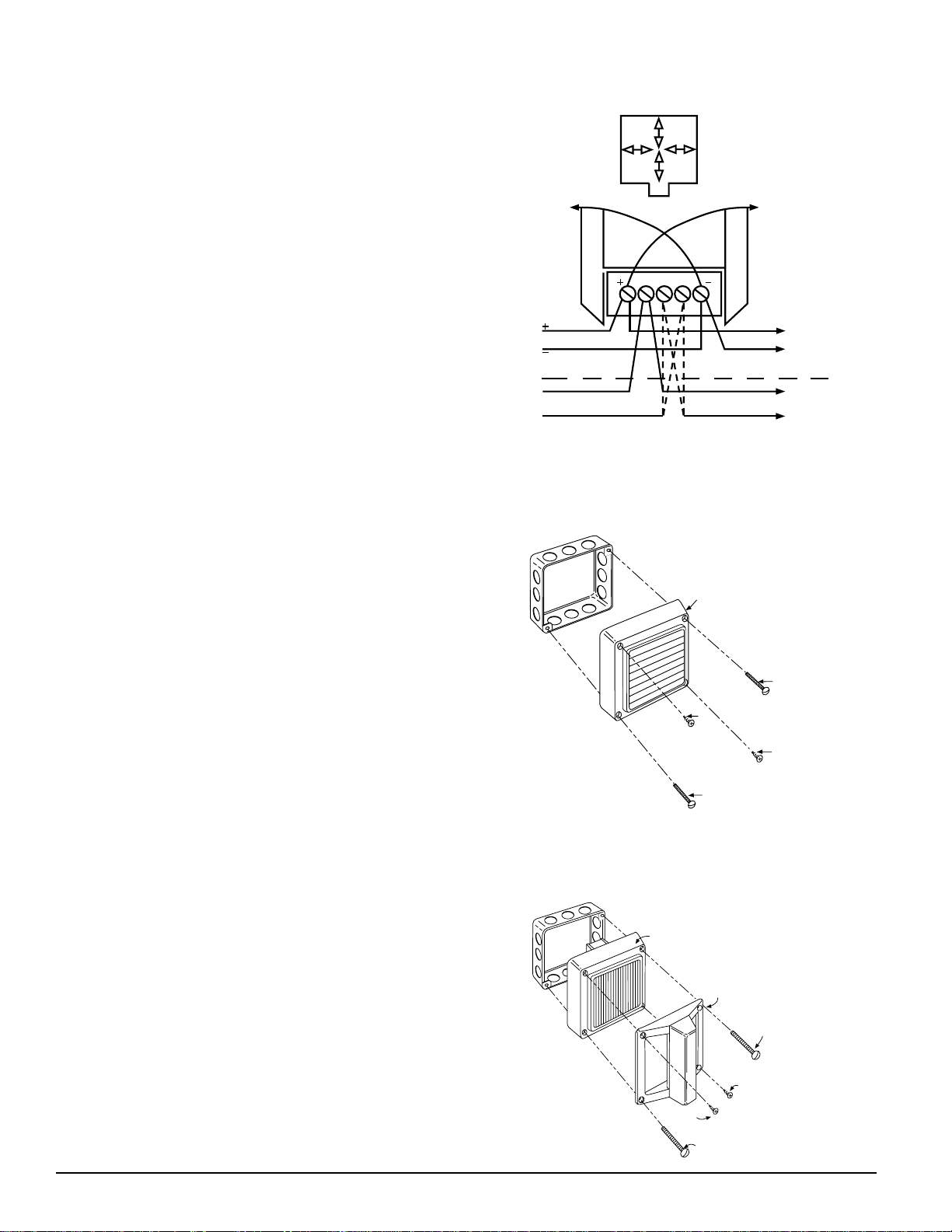
appropriate power post. When connecting this plug,
make sure the black wire is connected to the COM post
and the red wire to the numbered post.
NOTE: The plug MUST be installed for the speaker to oper-
ate. The speaker cannot sound or produce a trouble
indication at the panel if the plug is not installed.
Mounting
NOTE: The descriptions in this section assume that all prepa-
rations necessary for the installation of the speakers
have been completed. This includes the installation
of all conduit, electrical boxes, and wiring.
A. General
Both slotted head and phillips head screws are supplied
with the speaker/strobe. Use the slotted head screws to
mount the device or combination of devices on the electrical box. Use the phillips head screws in the two remaining
holes when only a speaker is being installed.
Figure 1. Wiring diagram shown in alarm condition:
2W
1/4W
1W
1/2W
FROM
PANEL OR
PREVIOUS
DEVICE
STROBE
25 OR
70.7V
RED
TO
STROBE
BLADE
COM 25 70.7
BLACK
STROBE
BLADE
TO
TO
NEXT
DEVICE
OR
EOL
TO
NEXT
DEVICE
OR
EOL
B. Surface Mount
1. Speaker Only (Figure 2)
(a) Wire the speaker as described in Electrical.
(b) Attach the speaker to a standard 4-inch electrical
box, using the two 8-32 X 17/16 slotted screws provided. Fill the remaining holes with the short #8
sheet metal screws.
2. Speaker with Strobe ( Figure 3)
(a) Use a small bladed screwdriver to remove the plastic
flash from the two strobe lug slots on the speaker.
(b) Identify the two diagonally opposite speaker holes
that will be needed for mounting the speaker on the
electrical box. The other two holes will be used to
attach the strobe and flush mount plate to the
speaker.
(c) Position the strobe over the speaker and guide its
two power lugs into the slots formed when the flash
was removed in step 2(a). Attach the strobe and
flush mount plate to the speaker using #8 phillips
head sheet metal screws through the pair of strobe
mounting holes that was selected in step 2(b).
(e) Slide the right angle connector on the red wire onto
the strobe power lug nearest the “F” in “FIRE”. Similarly, connect the right angle connector on the black
wire to the remaining lug on the opposite side of the
speaker.
(f) Connect the free end of the red wire to the STROBE
+ terminal (1) and black wire to STROBE – (5).
Then, connect a source of uncoded (continuous) 12
VDC or 24 VDC, as appropriate for the strobe model,
to the STROBE + and STROBE – terminals (1 and 5,
respectively). Be sure to observe polarity.
(g) Wire the speaker as described in Electrical and at-
tach it to the box, using two 8-32 X 17/16" slotted
screws.
Figure 2. Surface Mount:
BB-STD
V400
#8
S.M.
8-32X1-7/16
8-32X1-7/16
#8
S.M.
Figure 3. Speaker/Strobe Surface Mount:
V400
Signal Strobe
8-32x1-7/16
#8 Sht. Mtl.
#8 Sht. Mtl.
8-32x1-7/16
A78-1792-00
A78-1793-01
A78-1794-03
D900-03-00 2 I56-380-05
Page 3

Figure 4. SemiFlush Mount:
MP-SF
8-32x5/8
8-32X1-7/16
V400
#8 S.M.
#8 S.M.
8-32X1-7/16
8-32x5/8
#8
NUTS
Figure 5. Speaker, Strobe Semiflush Mount:
MP-SF
8-32x5/8
#8 Sht. Mtl.
V400
Signal Strobe
8-32x1-7/16
8-32x5/8
#8
NUTS
Figure 6. Speaker Flush Mount:
#8 NUT
8-32x1-5/16
V400
8-32x2-3/4
MP-F
8-32x1-5/16
8-32x2-3/4
BB-D
NUT
#8
A78-1795-01
#8 Sht. Mtl.
8-32x1-7/16
A78-1796-03
A78-1797-00
C. Semiflush Mount
1. Speaker Only (Figure 4)
(a) System Sensor semiflush mounting plates are
shipped with #8 nuts already installed from the
back.
(b) Route wiring through the opening in the semiflush
mounting plate opening and attach the plate to a
standard 4-inch square electrical box at diagonally
opposite corners, using the two 8-32 X 5/8 slotted
screws, provided.
(c) Wire the speaker/strobe as described in Electrical
and mount it on the plate using two 8-32 X 17/16"
slotted screws in diagonally opposite corners.
Thread a #8 sheet metal screw into each of the two
remaining holes in the speaker/strobe.
2. Speaker with Strobe (Figure 5)
Attach the mounting plate to the electrical box as described in paragraph C.1 before wiring the speaker/
strobe assembly as described in paragraph B.2.
D. Flush Mount
Flush mounting requires the use of a System Sensor BBD
deep box, or equivalent.
1. Speaker Only (Figure 6)
(a) Identify the two diagonally opposite speaker holes
that will be needed for mounting the speaker on the
electrical box.
(b) Use two 8-32 X 15/16" phillips head screws and
square nuts through the holes not used for mounting to attach the flush plate to the speaker.
(c) Wire the speaker as described in Electrical and
mount the speaker/plate assembly in the electrical
box using two 8-32 X 23/4" screws.
2. Speaker with Strobe (Figure 7)
(a) Use a small bladed screwdriver to remove the plastic
flash from the two strobe blade slots on the speaker
and flush mount plate.
(b) See Figure 3. Identify the two diagonally opposite
speaker holes that will be needed for mounting the
speaker on the electrical box. The other two holes
will be used to attach the strobe to the speaker.
(c) Position the strobe over the speaker and guide its
two power lugs into the slots formed when the flash
was removed in step 2(a). Attach the strobe to the
speaker using the #8 phillips head sheet metal
screws through the pair of strobe mounting holes
that was selected in step 2(b).
(e) Slide the right angle connector on the red wire on to
the strobe power lug nearest the “F” in “FIRE”.
Similarly, connect the right angle connector on the
black wire to the remaining lug on the opposite side
of the speaker.
(f) Connect the free end of the red wire to the STROBE
+ terminal (1) and black wire to STROBE - (5).
Then, connect a source of uncoded (continuous) 12
D900-03-00 3 I56-380-05
Page 4

VDC or 24 VDC, as appropriate for the strobe
model, to the STROBE + and STROBE - terminals
(1 and 5, respectively). Be sure to observe polarity.
(g) Wire the speaker as described in Electrical and at-
tach it to the box, using two 8-32 X 23/4" slotted
screws.
E. Plaster Ring Mount
1. Speaker Only (Figure 8)
Follow the Semiflush Mount procedure, except attach
the semiflush plate to the electrical box, using the two
slotted 6-32 X 5/8" screws.
2. Speaker with Strobe
Follow the Semiflush Mount procedure, except attach
the semiflush plate to the electrical box, using the two
slotted 6-32 X 5/8" screws.
F. Ceiling Mount (Models V400R, V400B, V400W,
SS24LOC and SS24MC only)
Models SS24LOC and SS24MC can be mounted on a ceiling
with the V400R or V400B only, using any of the methods
described in this manual. Therefore, follow the appropriate
procedure to mount the speaker or speaker/strobe on a
ceiling.
Figure 7. Speaker/Strobe Flush Mount:
#8 NUT
V400
BB-D
MP-F
#8
NUT
8-32x1
8-32x2-3/4
Signal
Strobe
8-32x1
Figure 8. Plaster Ring Mount:
V400
6-32x5/8
8-32x1-7/16
Standard
Backbox
8-32x5/8
Plaster
Ring
#8
NUTS
6-32x5/8
MP-SF
8-32x2-3/4
A78-1798-00
#8 S.M.
8-32x 1-7/16
#8 S.M.
A78-1799-02
Limitations Of Speakers And Speaker/Strobes
If the power option plug is not plugged into one of the option positions,
the speaker will not sound and there will be no trouble indication at the
panel. Always make sure that the individual speakers are tested after installation per NFPA regulations.
The speaker may not be heard. The loudness of the speaker meets (or
exceeds) the current Underwriters Laboratories standards. However, the
speaker may not attract the attention of a sound sleeper or one who has
recently used drugs or has been drinking alcoholic beverages. The speaker
may not be heard if it is placed on a different floor from the person in hazard or if placed too far away to be heard over the ambient noise, such as
traffic, air conditions, machinery, or music appliances that may prevent
alert persons from hearing the alarm. The speaker may not be heard by
persons who are hearing impaired.
The signal strobe may not be seen. The electronic visual warning signal
uses an extremely reliable xenon flash tube. It flashes at least once every
three seconds and exceeds current Underwriters Laboratories standards
for private mode viewing. The visual warning signal is suitable for direct
Three-Year Limited Warranty
System Sensor warrants its enclosed sounder to be free from defects in
materials and workmanship under normal use and service for a period of
three years from date of manufacture. System Sensor makes no other express warranty for this sounder. No agent, representative, dealer, or employee of the Company has the authority to increase or alter the
obligations or limitations of this Warranty. The Company’s obligation of
this Warranty shall be limited to the repair or replacement of any part of
the sounder which is found to be defective in materials or workmanship
under normal use and service during the three year period commencing
with the date of manufacture. After phoning System Sensor’s toll free
number 800-SENSOR2 (736-7672) for a Return Authorization number,
send defective units postage prepaid to: System Sensor, Repair Depart-
WARNING
viewing and must be installed within an area where it can be seen by
building occupants. The strobe must not be installed in direct sunlight or
areas of high light intensity (over 60 foot candles) where the visual flash
might be disregarded or not seen. The strobe may not be seen by the vi-
sually impaired and is not intended to meet American Disabilities Act
(ADA) requirements.
The signal strobe may cause seizures. Individuals who have positive
photic response to visual stimuli with seizures, such as persons with epilepsy, should avoid prolonged exposure to environments in which strobe
signals, including this strobe, are activated.
The signal strobe cannot operate from coded power supplies. Coded
power supplies produce interrupted power. The strobe must have an uninterrupted source of dc power in order to operate correctly.
System Sensor recommends that the speaker and signal strobe always be
used in combination so that the risks from any of the above limitations are
minimized.
ment, RA #__________, 3825 Ohio Avenue, St. Charles, IL 60174. Please
include a note describing the malfunction and suspected cause of failure.
The Company shall not be obligated to repair or replace units which are
found to be defective because of damage, unreasonable use, modifications, or alterations occurring after the date of manufacture. In no case
shall the Company be liable for any consequential or incidental damages
for breach of this or any other Warranty, expressed or implied whatsoever,
even if the loss or damage is caused by the Company’s negligence or fault.
Some states do not allow the exclusion or limitation of incidental or consequential damages, so the above limitation or exclusion may not apply to
you. This Warranty gives you specific legal rights, and you may also have
other rights which vary from state to state.
D900-03-00 4 I56-380-05
© System Sensor 1997
 Loading...